

Page 1
Signal®
Mirror Installation Instructions
2007-2011 Silverado/Tahoe/Suburban/Avalanche/Sierra/Yukon
THE safety accessory of the 21st Century.™
P/N 210-0133-0 Rev. A3 (7/19/11), BTV © 2006 Muth Company, LLC
Page 2
Professional Installation Recommended:
Warranty does not cover damage to the vehicle or mirror housing due to improper installation.
Muth Mirror Systems, LLC (MMS) assumes no responsibility with regard to the accuracy of this information.
MMS assumes no liability or responsibility resulting from improper installation, even in reliance upon this information.
Proper installation is the responsibility of the installer.
It is your responsibility to verify any circuit before interfacing with it using a digital multimeter.
INCLUDED ITEMS:
1-left and 1-right Signal® mirror
1-left and 1-right wire harness
2-wire taps
2-ring connectors
1-instruction manual
REQUIRED TOOLS:
Ratchet with extension or ratcheting screwdriver
10 mm socket
Socket wrench
Slotted screwdriver
Phillips screwdriver
Clip removal tool
Small pry bar (plastic)
Gopher rod (wire)
Electrical tape
Wire crimper and stripper
Needle nose pliers
Multimeter or wire tester
Sturdy gloves
Safety glasses or goggles
Utility knife
Heat gun
PROBLEMS OR QUESTIONS?
Technical Assistance is available by calling
Muth Mirror Systems Technicians at:
1-800-844-6616
Monday through Friday
Between 8:00 a.m. and 5:00 p.m. CST
Or through the Muth web site: www.muthco.com
Or via E-mail: techsupport@muthco.com
PLEASE READ INSTRUCTIONS PRIOR TO INSTALLATION.
Page 2
Page 3
Page 3
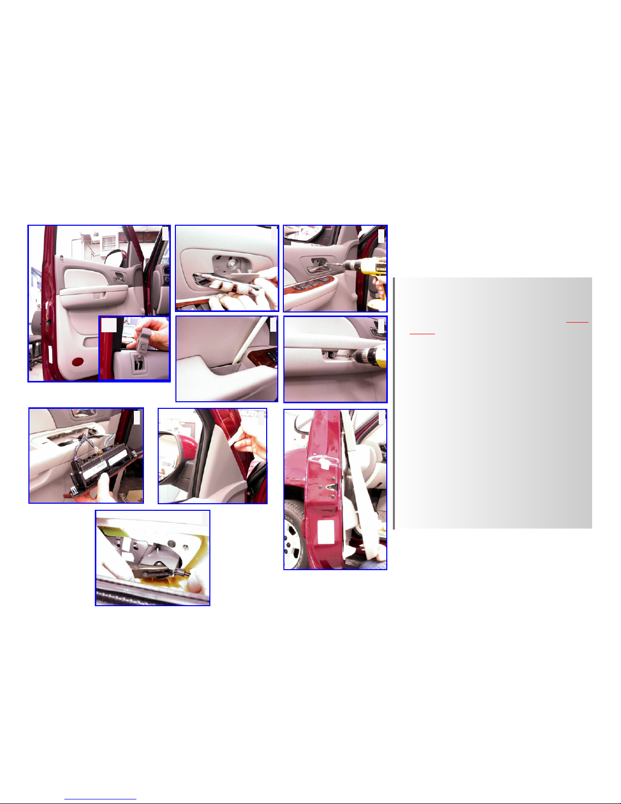
1) Start with opening the driver’s side door and
lowering the window. Remove lock lever (1A).
2) Using a plastic pry bar [slotted screwdriver],
slowly pry plastic cover to reveal screw. CAU-
TION: These plastic covers are fragile and
break easily. Be very gentle in disengaging
them.
3) Remove screw with a 10mm socket.
4) Slowly pry plastic cover using a plastic pry bar
[slotted screwdriver].
5) Remove the (2) revealed screws with a 10mm
socket.
6) Pry off the door panel controller using a plastic
pry bar. Disconnect wiring and remove the
controller.
7) With the plastic pry bar, pry around the triangular panel as shown.
8) Lift up and slowly pull door panel out partially.
9) Release the door lever rod with a needle nose
pliers. Remove and set door panel aside.
1235467
8
Door Panel Removal
1A
9
Page 4

Page 4
1) Carefully remove the (3) wire retention clips on door frame with a
clip removal tool.
2) Secure the mirror housing with one hand, remove the (3) nuts holding the mirror housing to the door frame using a 10mm socket.
WARNING: Not securing mirror housing with one hand before
loosening the nuts could cause the mirror housing to fall and become damaged. Carefully remove mirror housing from door frame
and set mirror housing on a cloth covered surface.
2
1
Mirror Housing Removal
Page 5

Page 5
1) Push down on the lower edge of the mirror until mirror pivots fully inward. Insert a clip removal tool into the gap between mirror and mirror housing, slowly press to release
mirror from motor actuator. If heated, disconnect heater
wires from heater terminals and remove mirror.
2) Remove the foam insulation on the housing sail. Using the
shorter of the two harnesses from the wiring kit, route the end
without the connector starting from inside the outboard edge
of housing, going behind motor actuator and thru to the
housing sail.
3) Pull the Signal® mirror wire harness thru housing sail leaving
about 4” to 6” of the wire harness inside mirror housing.
Connect the mating connectors on the new Signal® mirror and
the Signal® mirror wire harness. Using electrical tape, secure
the two connectors together to prevent future disconnection.
If heated, reconnect the heater wires to the heater terminals
on the back of the new Signal® mirror. NOTE: There is no
polarity so the wires may be interchanged.
4) Carefully tuck all wiring behind motor actuator. Not doing
so, could result in wiring interfering with mirror travel. If
anti-vibration tab is present, carefully tuck the anti-vibration
tab within mirror housing. Align the Signal® mirror motor
mount with the motor actuator in the mirror housing closest
to the upper edge of the housing. Slowly push downward
until motor mount snaps onto motor actuator. CAUTION:
Press down on all sides to ensure the new Signal® mirror is
fully seated and functional. Not doing so, could result in
new Signal® mirror falling off.
5) Route all wires thru sail foam insulation. Replace foam insu-
1
Mirror Replacement
234
5
WARNING: Safety glasses and sturdy gloves are required
for mirror replacement.
Page 6

Page 6
7) Guide all wire harnesses thru the access hole in the door frame
and position the mirror housing assembly on the mirror mount.
Attach the mirror housing to the mirror mount with three mirror mounting nuts. WARNING! Do not over tighten the mir-
ror mounting nuts.
8) Replace the (3) retention clips on the OEM wire to the door
frame. Route the Signal® mirror wire harness alongside OEM
wire as shown.
7
Mirror Replacement Continued
8
WARNING: Safety glasses and sturdy gloves are required for mirror replacement.
Page 7

1
2
Page 7
Wire Routing
1) Locate the grounding bolt shown on the door frame. Cut and split the red w/ black
stripe wire and the black wire on the Signal® mirror wire harness. Route the black wire
to the grounding bolt location. Cut the black wire to length, making sure enough slack
is left for splicing. Splice the black wire and attach it to one of the supplied grounding
rings. Attach the grounding ring to the grounding bolt on the door frame.
2) The wiring location for the driver side turn directional is located in the driver side door
panel control module. Replace all wiring onto the door panel control module. Locate
the LIGHT BLUE w/ WHITE stripe wire within the wire loom shown. Turn the ignition
key so that electrical power is on and activate the driver side turn indicator. Probe the
wire with the wire tester to verify that flashing turn directional power is present. Label
that wire as ‘driver side indicator’.
* Before proceeding, please read remainder of instructions for information regarding wiring
identification and options*
** Repeat all of the previous steps to replace the factory mirror on the passenger side
door with the new Signal® mirror.
3) The wiring location for the passenger side turn directional is located in the passenger
side door panel control module. Replace all wiring onto the door panel control module.
Locate the DARK BLUE w/ WHITE stripe wire within the wire loom. Turn the ignition
key so that electrical power is on and activate the passenger side turn indicator. Probe
the wire with the wire tester to verify that flashing turn directional power is present.
Label that wire as ‘passenger side indicator’.
*** SKIP TO LAST PAGE FOR WIRE SPLICING PROCEDURES ***
NOTE: If for some reason you cannot find the turn indicator wires, in the door panel areas,
as specified above. Please see next page for additional wire routing and locating information.
Page 8

Page 8
Page 9

1
2 3
4
USE THE INCLUDED WIRE TAPS AND FOLLOW THE FOUR STEPS ABOVE TO SPLICE INTO THE TURN INDICATOR WIRES
A. Make sure the harnesses are routed securely and enough slack is left for splicing.
B. Splice the RED wire from the driver side harness into the wire previously labeled ‘driver side indicator’.
C. Splice the RED wire from the passenger side harness into the wire previously labeled ‘passenger side indicator’.
D. Activate each turn indicator to verify that the Signal® mirrors are working properly.
E. Reconnect all original wiring. Turn the ignition power to on, check to verify all features are working properly.
F. Replace the plastic door frame moldings, trim, door panels, and all accessories.
Page 9
PROFESSIONAL INSTALLATION RECOMMENDED
Warranty does not cover damage to vehicle or mirror housing due to improper installation. Muth Mirror Systems, LLC (MMS) assumes no
responsibility with regard to the accuracy of this information. MMS assumes no liability or responsibility resulting from improper installation, even in reliance upon this information. Proper installation is the responsibility of the installer. It is your responsibility to verify any circuit before interfacing with it using a digital multimeter.
WARRANTY STATEMENT
The Signal® Mirror is warranted to be free from defects in materials and workmanship for a period of three years or 36,000 miles (whichever
comes first) from date of sale to original purchaser. This warranty excludes labor, broken glass, or other situations that cause harm to the
product after it has been shipped from the factory, such as damage, unreasonable use, modifications, or alterations. In the event of a defect, Muth reserves the right to evaluate the problem though Quality Control and, at Muth’s discretion, replace the defective product. Any
warranty or replacement part will be charged to the customer when shipped. Credit will be given when the defective part is returned to and
received by Muth , and the replacement is warranted.
Muth products are protected by these, and other pending, United States Patents: 6,076,948; 6,257,746; 7,104,676; 7,327,321;
6,749,325; 7,241,037; 7,192,172; 7,273,307; 7,416,318; 6,045,243; D394,833; D409,540; D428,373; D426,506; D430,088; D426,507; D428,372;
D429,202; D428,842; D425,466; D427,128
 Loading...