


Image/VGA-460
Frame Grabber
User’s Guide
MuTech Corporation
When Your Image Counts

Copyright 2000
MuTech Corporation
85 Rangeway Road
Billerica, MA 01862
USA
Telephone: 978-663-2400
Fax: 978-663-3444
Email: support@mutech.com
Website: www.mutech.com
Revision 1.0
09/15/00

i
Image/VGA-460 User’s Guide Revision 1.0
Table of Content
1 Introduction. . . . . . . . . . . . . . . . . . . . . . . . . . . . . . . . . . 1
1.1 Description of IV-460.............................................................................1
1.2 Options...................................................................................................2
1.3 VGA Display Modes........... .... .... ..........................................................3
1.4 Video Capture......................................................................................3
1.5 Software.................................................................................................5
1.6 Software Development Kits.................... ................................... ...........5
2 Installation . . . . . . . . . . . . . . . . . . . . . . . . . . . . . . . . . . . 9
2.1 System Requirements............................................................................9
2.2 Package Contents................................................................................ 9
2.3 Hardware Installation..........................................................................10
2.4 Cable Connections............................................................................11
2.5 Software Installation........................ .... .... ............................................11
2.6 Distribution Software...........................................................................13
3 Architecture . . . . . . . . . . . . . . . . . . . . . . . . . . . . . . . . 19
3.1 Block Diagram................. .... .................................... ............................19
3.2 Overview of the Component Blocks................................................20
Appendix A Jumper Settings. . . . . . . . . . . . . . . . . . . . . 23
Appendix B Specification of Connectors . . . . . . . . . . 25
B.1 Video Input Connector (P1) ..............................................................25
B.2 VIP Connector.....................................................................................27
B.3 J1 Connector.......................................................................................28
Appendix C Product Specification. . . . . . . . . . . . . . . . 31

ii
Revision 1.0 Image/VGA-460 User’s Guide
Introduction 1
Image/VGA-460 User’s Guide Revision 1.0
1
1 Introduction
Note, nomenclature definitions used in documents and product
literature:
Image/VGA-400 Series
or IV-4XX are used to refer to th e
whole line of products (including the old 400/450/450P and
the new 410/460, etc.)
IV-41X
is used to refer to the group of new products (i.e. 410,
460, etc.)
A specific produc t is r e fe r r ed by name, i.e. 400, 450, 460, etc.
1.1 Description of IV-460
Integrated VGA
Controller
The Image / VGA-460 (IV-460) is a single slot, PCI Bus frame
grabber and video digitizer with integrated VGA controller. It
captures and displays RGB/monochrome video on a standard VGA
or Super VGA screen. It works as a standard VGA Adapter in any
of the PCI Bus slots. The IV-460 includes device drivers for
Windows 9X, NT and W in2K. Dr ivers for other operatin g system s
may also be available. Please contact the Customer Support
Department of MuTech Corporation for the most up to date
information on drivers.
Standard or Non-
Standard Video
The IV-460 is capable of digitizing video signals from a standard/
non-standard camera. The video can be either monochrome or
RGB color. The timing can come from either composite video or
separate sync/clock. The digitized video data are stored in the onboard video buffer and mixed with the VGA signal for display on
the computer monitor.
Trigger & Expo.
Control
The IV-460 is capable of accepting an external Event Trigger,
generating a general purpose Strobe Signal to control the exposure
/ integration of the camera, and then receiving a Grab Trigger for
capturing single or multiple frames of video.
2 Introduction
Revision 1.0 Image/VGA-460 User’s Guide
Savage4 Pro
Accelerator Chip
from S3
The IV-460 needs a PCI Bus slot. If there is a VGA adapter on the
computer motherboard, the IV-460 can replace it an d become the
primary VGA display controller. The VGA controller of the IV460 is the S3 Savage4 Pro Accelerator Chip (possibly with
different versions and different revisions). The IV-460 is delivered
with onboard VGA BIOS from S3.
Connectors
The IV-460 has three connectors. The first is the Video Input
Connector which takes either Monochrome Video or RGB Color
Video from a camera. This is a High-Density DB-15 male
connector. This connector also provides connections for the Event/
Grab Trigger, the Strobe, and camera power output. The second is
the VGA Output Connector, which provides VGA display signals
to the computer monitor. This is a High-Density DB-15 female
connector. The third is a 50 pin header connector on top of the
board, which can be connected, via a ribbon cable to a DB-50
connector on a second bracket. This connector provides th e
maximum possible connections to the IV-460 board, including 4
monochrome video, 2 sets of RGB video, 2 sets of external sync
and clock, 4 sets of Event-Strobe-Trigger and camera power. For
customers who need to utilize these connection, MuTech provides
an optional Ribbon Cable (MVC-D32). A custom cable from the
DB-50 connector must be made by the customer.
Major
Components
The Image / VGA-460 board consists of the following major
components:
PCI bus interface
VGA graphics controller
RAMDAC
Buffer memory, 8 MB (16 MB optional)
10 bit monochrome A/D Convert e r (only 8 bit data are used)
3 x 8 bit RGB A/D Converter
Input LUT
Grab and Exposure Control Unit
Sync Stripper, Separator and PLL
The auxiliary circuits
1.2 Options
The following options are available for the IV-460:
Introduction 3
Image/VGA-460 User’s Guide Revision 1.0
Options
8/16 MByte Video Buffer Memory
Security Device -a 256 x 8 bit EEPROM (XICOR X24C02)
with write protection jumper is implemented on the board
(must be provided by OEM or software developer)
RS-170 or CCIR Sync Generator to provide standard drive
signals to camera
1.3 VGA Display Modes
Without the video window display, the IV-460 supports all VGA /
SVGA display modes, only limited by the amount of on board
memory.
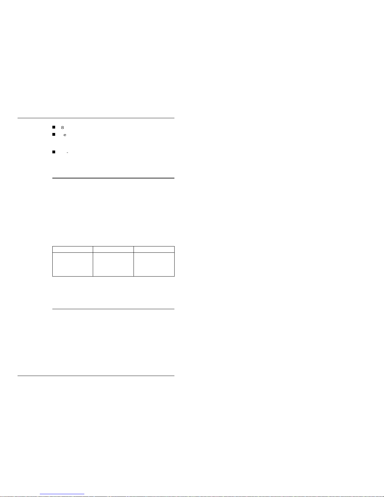
When the video window is on, the display resolution and/or color
depth are further limited. The IV-460 has shared memory
architecture. In this architecture, the video display, the VGA
overlay, the video capture, and the host access all compete for the
same limited memory bandwidth. This will limit the maximum
spatial resolution and/or color depth. The next table shows the
resolution and color depth tested for the IV-460.
Note
The above listed resolution and color depth are also limited
by the on board memory amount.
1.4 Video Capture
Video Inputs
The IV-460 board digitizes either RGB color or monochrome video
signals. It supports up to 4 monochrome video inputs or up to 2
RGB video inputs. When the default connector (DB-15HD) is
used, the maximum video input combination is limited by the
available connections. The channel switching is under software
control. The monochrome video is digitized into 8 bits which is
further combined with dummy chrominance data to form 16 bit
pixels in YCbCr 4:2:2 format (per the CCIR601 standard). The
RGB color video is digitized into 3 x 8 bits which are either stored
Screen Resolution Maximum Colors Refresh Rate
640 x 480
800 x 600
1024 x 768
1280 x 1024
16 M
16 M
16 M
16 M
85
85
85
75

4 Introduction
Revision 1.0 Image/VGA-460 User’s Guide
in 24 bit pixel format or combined with a dummy byte to form 32
bit pixel format. Capturing and displaying of the video are real time
(30 fps for RS-170, 25 fps for CCIR).
Video Window
The IV-460 supports only one video window. Software can control
the settings of the Top / Bottom Reference Level of the A/D
Converter, as well as the Clamping Leve l of the video si gnal. A 256
x 8 bit input LUT i s avai lab le for m on ochr ome vide o. Thr ee 256 x
8 bit input LUTs are available for RGB video. In both cases, there
are 16 banks in each of the LUTs. The user may pre-load them with
16 different look-up-tables and switch them during the vertical
retrace periods. All LUTs may b e bypassed.
Scaling
The video scaling is implemented by programming the PLL. For
standard RS-170(CCIR) video, the default PLL setting will
generate 640(768) pixels per line. This corresponds to non-scaled
capture with a 1:1 aspect ratio.
Display Mixing
There are basically three different working modes for displaying
and mixing of video and graphical content. T hey are the:
Opaque Mode
Color Key Overlay Mode
Chroma Key Underlay Mode
Opaque Mode
In the Opaque Mode, the video content is displayed in the video
window and the graphical conten t is di splayed on another part of
the screen.
Color Key
Overlay Mode
In the Color Key Overlay Mode, the graphical content may overlay
the video content in the video window. This overlay is controlled
by the Color Key (or Index Key). If the color of the graphical
content is the same as the Color Key, the user will see-through that
pixel and see the video content under it. Otherwise the user will see
the graphical content.
Chroma Key
Underlay Mode
In the Chroma Key Underlay Mode, the graphical content may
underlay the video content inside the video window. This is
controlled by the Chroma Key Register settings (one set of registers
for each of the R, G, and B channels, in the case of color video). If
the video pixel color is within the Chroma Key color range, the user
will see through the video pixel to the graphical content under it.
Otherwise the user will see the video content.
Zooming
The captured video m ay be zoomed up by an arbit rary ratio, i n both
directions, on the way to being displayed on the monitor.

Introduction 5
Image/VGA-460 User’s Guide Revision 1.0
Trigger &
Exposure Control
The IV-460 is designed for industrial use. It provides a general
purpose Event Trigger Input, a general purpose Strobe Output and
a Grab Trigger Input. The Event signal is used to start the camera
control-capturing sequence. The Strobe could be used to reset the
camera, to control the exposure / integration time, or to strobe a
flash light. When the desired frame / field is ready, the Grab
Trigger is used to capture the desired frame / field. There are 4 sets
of E-S-T signals, selectable by software, so each of the video
channels may have its own control.
1.5 Software
Utility Programs
Several utility programs are delivered with the IV-460 board. They
can be used for testing the installation, simple debugging, and
demonstration purposes. They can also be used as utilities for
capturing video and saving to files. The utility programs provided
support Extended DOS, Windows 9X, NT and Win2K. Also
distributed are VGA drivers for Windows 9X, NT and Win2K
(these drivers are available for down-loading from the S3 home
page as well as from the MuTech home page). All drivers are
directly licensed from S3.
MuTech does provide full customer support for the utility
programs and the Software Devel opment Kits described below.
1.6 Software Development Kits
MuTech offers Software Development Kits (SDKs) for OEMs or
any users developing application programs for the IV-4XX Series
Product Line. These SDKs support Extended DOS and Windows
9X, WinNT/2000. Each of the SDK includes:
LIBs and/or DLLs
include files
sample source codes (showing typical calling sequences and
the usage of the core functions) in both C and VC++ formats.
MuTech does NOT modify any of the VGA drivers and does
NOT have any expertise to provide customer support for
them.

6 Introduction
Revision 1.0 Image/VGA-460 User’s Guide
make files
The major groups of functions in the SDKs are listed below. For
each group, a simple description is given to show the tasks of
functions in the group. For definitions of the logical windows/
frames used in this section, please refer to the Image / VGA-4XX
Software Development Guide.
Board
Initialization
Group
Included in this group are functions used to open/close the IV-460
board, to initialize the board to a default state, and to retrieve the
information about the board, the current configuration, the SDK
version, etc.
Capture Control
Group
This group consists of the functions which are used to control the
Capturing Process. This includes defining the Grab Window,
setting the Scale Factors, defining the Video Frame, and starting/
stopping the grabbing. Also, this group includes functions to wait
for the Vertical Sync or for the End of a Frame.
Display Control
Group
This group consists of the functions which are used to control the
Displaying Process. This includes defining the Display Image
Frame, setting the Display Zoom Factors and setting the Image
Windows on screen. Other functions in this group control the
Overlay Mode and the settings of the Color/Chroma Key values.
Front End
Adjustment
Group
The functions in this grou p control the adjustm ent of features of the
input video signal. For example, the TV standard, the channel
selection, the settings of the Gain and Offset are all controlled in
this group.
Look Up Table
Group
The functions in this group are used to load the input video LUT,
to use or to bypass the input LUT, or to switch the LUT banks.
On-board
Memory Access
Group
Functions in this group are provided to read/write the video
memory buffer. When accessing the buffer through these functions,
the SDK hides the low level details from the caller, and presents the
video data as lines in a 2-D memory array.
File I/O Group
The functions in this group provide high speed image file read/
write, in one of the supported file formats (Bitmap, TIFF or
TARGA).
Miscellaneous /
Utility Group
Functions in this group provide support for some minor tasks for
the user. For example, wait for VGA vertical retrace, etc.

Introduction 7
Image/VGA-460 User’s Guide Revision 1.0
Advanced
Feature Group
This group includes the functions to handle the Event signal,
triggered capture, Strobe signal generation and different IRQ
services.
For details about the IV-4XX SDK, please refer to the
Image /
VGA-4XX Software Development Guide
.

8 Introduction
Revision 1.0 Image/VGA-460 User’s Guide
Installation 9
Image/VGA-460 User’s Guide Revision 1.0
1
2 Installation
2.1 System Requirements
Before installing the IV-460 Board, ensure that the following
requirements are satisfied
The system must have at lease one PCI slot available.
If the system has a VGA controller on the motherboard, the
IV-460 can be plugged into one of the PCI slots and will take
over as the primary VGA controller. If the system has a VGA
adapter board, it must be removed and replaced with the IV460 board.
To capture an image, one of the following cameras is needed:
RS-170/CCIR monochrome camera
RS-170/CCIR RGB color camera
2.2 Package Contents
The standard shipping package of the Image / VGA-460 include s
the following items:
IV-460 Board
Image / VGA-460 Frame Grabber User’s Guide (this
document)
IV-4XX Distribution CD (or Diskettes), which contains the
latest readme file, the software installer, the VGA drivers and
the demonstration utility for the desired Operating Environment (some Operating Systems must be specially ordered).
Product Options
The following options must be ordered separately:
VC-DB15-10 Video Cable, which provides 3 monochrome
video, 1 set of RGB video and connections for E-S-T signals.

10 Installation
Revision 1.0 Image/VGA-460 User’s Guide
VC-DB15-12 Video Cable, which is similar to the VC-DB1510 Cable but with 3 monochrome and 1 set of RGB video, or
2 sets of RGB video inputs.
MVC-D32 Ribbon Cable Assembly which provides the
connections between the 50 pin header and a DB-50 connector
on a separate bracket.
Image / VGA-4XX Software Development Kit (for the Operating System of your choice), which includes the diskette(s)
and the Image / VGA-4XX Software Development Guide man-
ual.
Sync-Gen Option must be ordered separately, if HD & VD
outputs are needed to drive the camera.
Security Device and its programming utility must be ordered
separately, if an OEM customer needs to add some protection
to their software.
Please check the packing contents carefully; always check the
readme file on the Distribution Diskette for the latest change of the
package contents. If something is missing or damaged, contact the
MuTech Customer Support Department immediately. The
telephone number and e-mail addr ess are listed on the cover pages.
2.3 Hardware Installation
The Image / VGA-4XX Series Boards are Plug and Play devices.
There is no I/O address or Memory address to set.
Input
Termination
The jumpers on the IV-460 board are for input termination (75
Ohms). For most standard video sources, the video inputs should be
terminated by 75 Ohms. These are the factory default settings. If
the user does need to change the termination, please refer to
Appendix A: Jumper Settings
.
Note, we strongly recommend that the user read the readme
file in the Image/VGA-4XX Series Distribution Disc(Diskettes) first. It contains the latest information regarding
hardware installation procedures.

Installation 11
Image/VGA-460 User’s Guide Revision 1.0
2.4 Cable Connections
There are only two cable connections necessary for the IV-460.
They are the VGA monitor cable and the video input cable.
Figure 2.1: IV-460 Cable Connection Diagram
The VGA output connector of the IV-460 is a DB-15 High
Density
Female
Connector located in the lower part of the
bracket. Attach the cable coming from the VGA monitor and
secure the screws to complete this connection.
The Video Input connector is a DB-15 High Density
Male
Connector located in the upper part of the bracket. If the
MuTech VC-DB15-10 cable was purchased, it should be
plugged in, then connect the video group (C. Video or RGB
Video) and the trigger group (Event, Strobe or Grab Trigger)
of connectors according to the application needs. For the cable
color specification or if a custom cable is to be made, consult
Appendix B: Specification of Connectors
.
Note, it is not necessary to connect the video input signal in order
for the IV-460 to work. However, the demonstration programs
provided by MuTech do require that a video signal be connected.
2.5 Software Installation
The software installation can be divided into two parts.
1. Installation of the VGA driver(s).
0RQLWRU &D EOH
9&'%
RU 9&'%
&DEOH
Camera
IV-460 Board
&DEOHFGU
9
Monitor

12 Installation
Revision 1.0 Image/VGA-460 User’s Guide
2. Installation of the demonstration utilities.
The following sub-sections describe these procedures.
Windows NT
Driver
Installation
The installation procedures are described step by step in the readme
file found on the Image/VGA-41X VGA Driver Disk. Please follow
the instructions there.
Windows 9X
Driver
Installation
The installation procedures are different for first time installation
and for new version upgrades. These procedures are described step
by step in the readme file found on the Image/VGA-41X VGA
Driver Disk. Please follow the instructions given there.
DOS Extender
Distribution
Software
Installation
To install the Distribution Software provided by MuTech follow
these procedures.
1. Put the Distribution Diskette in drive A.
2. Under DOS, change to A:\, run INSTALL, and then follow
the instructions.
3. The installation/setup program will ask the user to enter the
base directory for all the IV-4XX software. The default directory name is “C:\IV-400”, but the user can select a different
drive/name. The installation setup program will create this
base directory and several sub-directories on the drive specified by the user and copy all software into them.
Windows
Distribution
Software
Installation
1. Put the
Image/VGA-4XX Series Distribution Disk for Win-
dows
in drive A.
2. Open My Computer folder, and select A: drive. Double click
on the Setup.exe icon to start the setup program. Follow the
instructions on the screen to complete the installation.
3. There are a total of five drivers/programs that can be installed
by the setup program: core driver, MCI driv er, TWAIN driv er,
Vide o Captur e dri v er , and IV-4XX Demo program. The user i s
able to choose which drivers should be installed.When the
Setup Type dialog box is displayed, select Typical to install
all drivers, select Compact to install only the IV-4XX Demo
program and core driver, select Custom to install specified
MuTech recommends that the user read the readme file in
the Image/VGA-4XX Series Distribution Disk first. It contains the latest information regarding the software installation procedures.

Installation 13
Image/VGA-460 User’s Guide Revision 1.0
drivers.
4. Upon completion of the Windows setup, the program will
also have:
Created a variable called “IV-400” under the [MuTech]
section of the WIN.IN file, and assigned the base directory name to it. This is used to locate all files needed by the
IV-4XX software.
Created a program group called MuTech and setup an
icon for the IV-4XX Windows demonstration program.
Modified the Windows NT registry to configure the kernel driver.
Copied the driver files to:
for Windows NT,
C:\WINNT\SYSTEM32\DRIVERS\
and C:\WINNT\SYSTEM32
for Windows 9x,
C:\WINDOWS\SYSTEM
The system must be restarted to make everything effective. Also,
this procedure is documented in the readme file of the Image/VGA-
4XX Series Distribution Disk.
After installation of the software, it can used to check the IV-41X
hardware and software. The next section provides descriptions of
the software usage.
2.6 Distribution Software
Demo. Utility
This section contains descriptions of all software distributed with
the Image / VGA-41X boards. The software includes drivers for
Windows 9x and Windows NT/2000, a DOS demonstration utility
named IV4DEMOW.EXE and a Windows demonstration utility,
named CIV4DEMO.EXE for Windows 9x, and NIV4DEMO.EXE
for Windows NT/2000.
Camera Config.
Files
Also distributed is a group of camera configuration files which are
tested with some of the popular cameras.

14 Installation
Revision 1.0 Image/VGA-460 User’s Guide
CamConfig
Utility
To simplify the generation of the required camera configuration
file for the specific camera, a utility program for camera
configuration file generation and modification is included in the
distribution package. In general, the user should pick the most
similar camera configuration file from the group of files, load it
into the CamConfig Utility, modify the configuration, test the new
configuration file, then save it.
Drivers
All VGA drivers for the IV-41X board are licensed from S3
Incorporated. MuTech provides these drivers for the con venience
of our users. From time to time, S3 will either release newer
versions of drivers or add driver supports to new operating systems,
the user can download the latest drivers from the MuTech home
page: website“www.mutech.com”.
The drivers provided for the S3 Chip are listed below:
Windows 9X
Windows NT 4.0
S3 Technical
Support
Note, MuTech did NOT develop the VGA drivers, nor does it have
the resources or expertise to support the VGA drivers. For any
VGA driver issue or anything regarding the S3 SavagePro 4
Accelerator Chip, please contact S3 Technical Support at:
(408) 980-5400
or visit:
http://www.s3.com/
or write to:
S3 Incorporated
2770 San Thomas Expressway
PO Box 58058
Santa Clara, CA 95052-8058

Installation 15
Image/VGA-460 User’s Guide Revision 1.0
2.6.1 Windows Demonstration Utility
This section describes the basic functionality of the Demonstration
Utility for Windows 9X and Windows NT/2000. DOS users can
skip this section.
To start the DEMO utility, double click the program icon in the
MuTech Program Group. When the program starts, it shows a
group of menu selections. They are File, Grab, Trig/ Exp., Adjust,
Snap, and Help. The following list describes the functions provided
under each of the menus.
File
Load/Save image from/to file. The file formats supported are
Bitmap, TARGA and TIFF. The current configurations can also be
saved to a file, and can be loaded to override the defaults the next
time the utility is run.
Grab
Start/stop image capture, enable/disable the video display, set the
grab to frame mode or field mode. Start of capture can also be
specified on ODD/EVEN/NEXT field (for interlaced video). A
Board Configuration D i alo g Box is pr ovi de d und e r thi s me nu .
Trig/Exp.
Provides interfaces to Event, Strobe and Trigger features. The
following settings can be controlled
Select Event channel/polarity of Event Signal. Enable/disable/
reset/generate Event.
Select Strobe channel/polarity of Strobe Output/other Strobe
parameters. Enable/disable Strobe.
Select Trigger channel/modes/polarity of trigger signal. Enable/disable/reset/generate trigger.
Adjust
Under this menu, the followings can be set or adjusted.
Capture of scale factors (H & V)
TV standard (or non-standa rd) selection
Channel selection
Gain/Offset control (or Top/Bottom/Clamping control)
Enable/bypass the LUT, and the selection of different LUTs
Display zoom factors (H & V)
Keying mode adjustment: se l ect ing mode and changing key
values

16 Installation
Revision 1.0 Image/VGA-460 User’s Guide
Snap
Use this menu to capture a single frame/single field.
Help
Use this to find information about the utility.
2.6.2 DOS Demonstration Utility
This section describes the basic functionality of the DOS
Demonstration Utility.
To start the IV4DEMOW utility, change to the IV-400 Base
Directory. The default is “C:\IV-400”. If a different directory has
been specified during installation, change to that one. Then change
to the DOS4GW sub-directory under the Base Directory. Make
sure the DOS4GW.EXE file is in the same sub-directory. Run
IV4DEMOW from there. When the program starts, it shows a
group of menu selections. They are File, Grab, Trig/ Exp., Adjust,
Snap, Save Current Configuration, Show Board Information, and
Exit. The following list gives the functions provided under each of
the menus.
File
Load/Save an image from/to file. The file formats supported are
Bitmap, TARGA and TIFF.
Configuration
Provides interface to configure the board or load a came ra
configuration file.
Grab
Start or stop vi deo c apt u r e, en a ble or d i sabl e video display, s et the
grab to frame mode or field mode, and specify the start of capture
on ODD / EVEN / NEXT field (for interlaced video).
Trig/Exp.
Provides interfaces to Event, Strobe and Trigger features.
Following settings can be controlled:
Select Event channel/polarity of Event Signal. Enable/disable/
reset/generate Event.
Select Strobe channel/polarity of Strobe Output/other Strobe
parameters. Enable/disable Strobe.
Select Trigger channel/modes/polarity of trigger signal. Enable/disable/reset/generate trigger.
Adjust
Under this menu, the follow settings and adjustments are possible.
Capture of scale factors (H & V)
TV standard (or non-standa rd) selection
Channel selection

Installation 17
Image/VGA-460 User’s Guide Revision 1.0
Gain/Offset control (or Top/Bottom/Clamping control)
Enable/bypass the LUT, and the selection of different LUTs
Display zoom factors (H & V)
Snap
Use this function to capture a single frame or a single field.
Save
Configuration
Use this to save the current state to a file and to override the
defaults the next time the utility is run.
Show Board
Information
Provides information about the IV-460 board

18 Installation
Revision 1.0 Image/VGA-460 User’s Guide

Architecture 19
Image/VGA-460 User’s Guide Revision 1.0
1
3 Architecture
3.1 Block Diagram
Figure 3.1
: Image / VGA-460 Block Diagram
Figure 3.1 shows the major components of the IV-460 board. These
major components are:
Video Input and A/D Converters
Input LUT
PLL, Sync and Timing Unit
Capturing and Exposure Control Unit
Display Processor, PCI Interface, Stream Processor and
RAMDAC
Video Buffer Memory - SDRAM 8 or 16MB
Streams Proc.
LUT & DAC
VIP
Connector
8 Bit A/D
X 3(RGB)
SDRA M
Buf.
8/16 M B
Bus I/F &
Central
Control Unit
Grab &
Exposure
Control
PLL,
Sync &
Timing
Event Trigger
& Grab Trigger
Strobe /
Integ ra tion
VGA
BIOS
PROM
4X8 B it
LUT
(XR G B )
Syncs
Video
VGA
OUT
PCI Bus
S3 SavagePro
64 bits
8 bits
460_Blk.CFL
REV. 1.0 09/01/00
HD + VD
(Opti onal)
H/V Sync
& P. Clk
8 Bit A/D
(Mono)
Digital
Video
Video IN
(RG B /
Mono.)
16 bit/
24 bit
16 bit/
32 bit

20 Architecture
Revision 1.0 Image/VGA-460 User’s Guide
VGA BIOS PROM
3.2 Overview of the Component Blocks
A simple functional description of each of the blocks is given in
this section.
Video Input &
A/D Converters
This unit has the following functional blocks:
Video Input MUX: Selects between 4 monochrome video
and 2 sets of RGB video signals. If only a DB-15HD connector
is used, the selection is further limited.
A/D Converters: Digitize the video signal.
PLL: Generates the video pixel clock which is locked to the
video signal.
Sync Separator: Generates the H+V sync and the field signal
needed by the rest of the board.
Input LUT
The input LUTs are SRAMS. The loading of the LUT is relatively
slow and is not recommended during grabbing. The user should
pre-load the banks with possibly needed LUTs before starting the
grab.
The input LUT may be bypassed by software. This function will
send unmodified data to the display processor.
Monochrome mode has 1 luminance LUT channel, there is no
LUT for chrominance chennel.
RGB mode has 4 LUT channels, three each for R, G and B, the
4th one is a dummy LUT.
In both modes, there are 16 banks of each LUT channel. The
banks may be switched quickl y, duri n g ve r ti cal re t r ac e, by
software.
Grab & Exposure
Control
This unit controls the triggered capturing, and provides the general
purpose Strobe signal to control the exposure. This block includes
the following sub-blo c ks:
Signal Mux: Several MUX control the selection of 4 channels
of E-S-T signals. They may be used to service up to 4 cameras.
Event Trigger Input: This TTL level input controls the enabling/disabling of the event trigger as well as its polarity.

Architecture 21
Image/VGA-460 User’s Guide Revision 1.0
Strobe Generator: This TTL level output strobe (used for
exposure or integration control) can be generated from either
the Event Trigger Input or a software command. The duration/
polarity are also controlled here.
Grab Trigger Input: Controls the starting/stopping the video
capture. The polarity is also controlled by this unit.
Trigger Functions
These trigger functions are available.
Stop acquire on trigger
Start continue acquire on trigger
Grab next frame.
Grab next field.
Grab next odd field.
Grab next even field.
Frame Buffer
The Frame Buffer is described below:
Total Size: 8 MB (16 MB optional).
Organization: As a one-dimensional linear array (data are
stored consecutively).
Locations: The VGA data and video data share the same
memory buffer, but at different segments. Usually, the VGA
data occupies the first segment, and the video data is stored
toward the end of the buffer.
Monochrome Pixel Data Format: The pixels are stored in
the format Y-dummy(0x80)-Y-dummy(0x80).
RGB Pixel Format: The pixels are stored in either 32 bit format - XRGB (X is the MS Byte), or 24 bit format - RGB (R is
the MS Byte).
Bus Interface and
Central Control
Unit
This is the most complicated block. It consists of the following subblocks:
PCI Bus Interface: Provides the interface for CPU access.
Capturing Control: Controls the interface to the A/D
Converter, and the start/stop of the video capture.
Memory Controller: Interfaces with the Frame Buffer,
generating the addresses as well as the control signals for the

22 Architecture
Revision 1.0 Image/VGA-460 User’s Guide
buffer memory.
Display Controller: Controls the data fetching, the timing,
the sync signal generation etc. for the display process.
Other Interfaces: Miscellaneous interfaces, e.g. on board serial interface.
Display Block
This block performs the function of displaying the VGA and video
data on the monitor screen. It consists of:
Streams Processor: Controls the data flow of the VGA and
video streams for display.
LUT: VGA Look-Up Ta bl e, defines the display palette.
Color Space Converter: Transforms the YCbCr video data
into RGB format.
Key & MUX: Generates the KEY from Color/Chroma
information, then uses the KEY to control the selection of the
data to the DAC block.
DAC: Converts the digital data into an analog RGB signal and
drives the monitor.
VGA BIOS
This is an EPROM. The BIOS is read out during boot-up through
the PCI interface block.

Jumper Sett ings 23
Image/VGA-460 User’s Guide Revision 1.0
1
Appendix A: Jumper Settings
There are 4 groups of jumpers on the Image/VGA-460 Board. The
first group (JP) is for 75 Ohm termination of the video input
signals. The second (PJ) is for camera power output control. The
third (CJ) group is for user configuration control. The last (WJ) is
for Security PROM write protection. Table A.1 lists the IV-460
jumpers, their functions and their factory default settings. Figure
A.1 shows the positions of the jumpers on the IV-460 board.
Table A.1: IV-460 Jumpers and Factory Default Set tings
Note, the RED0 and GRN0 video inputs are always terminated
with 75 Ohms
.
Jumper Function Default
JP1 Terminate V0 (RED1) Channel with 75 ohms IN
JP2 Terminate V1 (GRN1) Channel with 75 ohms IN
JP3 Terminate V2 (BLU1) Channel with 75 ohms IN
JP4 Terminate V3 (BLU0) Channel with 75 ohms IN
JP5 Terminate HS0 (CSync0) with 75 ohms IN
JP6 Terminate VS0 (CSync1) with 75 ohms IN
JP7 Terminate EXTCLK0 with 75 ohms OUT
JP8 Terminate EXTCLK1 (D-50 only) with 75 ohms OUT
JP9 Select +12V (R) or +5V (L) as Camera Power RIGHT
JP10 +12V is from PCI Bus (Left - max. 0.5A) or Power
Connector H4 pin 1 (Right - option only)
LEFT
JP18 User configuration jumper, IN = 0 IN
JP19 User configuration jumper, IN = 0 IN
JP12 Security PROM write protection, IN = Write
Enabled
OUT
JP13 NTSC(IN)/PAL(OUT) timing selection for Sync
Generator (Sync-Gen Option only)
(optional)
IN

24 Jumper Settings
Revision 1.0 Image/VGA-460 User’s Guide
Figure A.1: Jumper Positions and Default Settings on IV-460
Board
JP1
JP2
JP460.cdr
V1.0 (09/14/00)
P1
JP3
JP4
P2
H2
JP18
JP19
JP9 JP10
26
125
2
JP5
JP7
1
J1
JP12
JP13
2
H4

Specification of Conn ec t ors 25
Image/VGA-460 User’s Guide Revision 1.0
1
Appendix B: Specifica tion of Connectors
There are four connectors on the IV-460 board.
P1 is a DB-15 High Density male connector used for video
input.
P2 is a DB-15 High Density female connector used for VGA
output.
VIP (also marked as H2) is a 26-pin header (13 x 2) used as the
Feature Connector.
J1 is a 50-pin header (25 x 2) used as an extended Input/Output
Connector providing all available signals.
This section gives connection information for P1, J1 and H2. For
connector P2, the standard VGA pin-outs are used.
B.1 Video Input Connector (P1)
Connector P1 is used for video input, external sync input/output,
Event Trigger / Grab Trigger input, camera power output and
Strobe/Integration and Control output. The pin-outs are listed in the
table below.

26 Specification of Connectors
Revision 1.0 Image/VGA-460 User’s Guide
Table B.1: Pin Assignment and Cable Color of Video Input
Connector (P1)
Figure B.1 shows the pin positions of the P1 Connector, when facing the pins.
Figure B.1: DB-15 High Density Male Connector
Pin # Signal Name Description VC-DB15-10
Color
VC-DB15-12
Color
1 V0/R1 V. In #0 or Red In #1 Red Red
2 V1/G1 V. In #1 or Green In #1 Green Green
6 V2/B1 V. In #2 or Blue In #1 Blue Blue
11 R0 Red In #0
Black-DIN
Red/White
12 G0 Green In #0
White-DIN
Green/White
14 B0/V3 Blue In #0 or V. In #3 N/C Blue/White
7 AGND Analog Ground
13 EVENT0 Event Trigger 0 Input Grey Gray
9 TRIGGER0 Grab Trigger 0 Input Black Black
3 STROBE0 Strobe/Integ. 0 Output White White
4 SYNC0/HS0/HDCSync In #0 or HSync In
#0 or HDrive Out
Yellow Yellow
5 SYNC1/VS0/VDCSync In #1 or VSync In
#0 or VDrive Out
Brown Brown
15 EXTCLK0 Ext. Clock In #0 Orange Orange
8 +12V/+5V Power Output N/C N/C
10 GND Digital/Power Ground

Specification of Conn ec t ors 27
Image/VGA-460 User’s Guide Revision 1.0
B.2 VIP Connector
Table B2 shows the signal on the VIP (H2) connector.
Table B.2: Signals on VIP (H2) Connector
Pin # Signal Name Description
1 D0 Input Data (LSB-multiplexed YUV)
3 D1 Input Data
5 D2 Input Data
7 D3 Input Data
9 D4 Input Data
11 D5 Input Data
13 D6 Input Data
15 D7 Input Data (MSB)
17 CLOCK Pixel Clock Input
8 HS H Sync Input
12 VS V Sync Input
10 FLD Field Input (optional)
14 SCL I IC Clock Output (optional)
26 SDA IIC Data Input/Output (optional)
2, 4, 6,
16, 18,
20, 22,
23, 25
GND Ground
Pins below are extension to VIP
19 IDQ Pixel Clock Qualifier
28 D8 Input Data High Byte (LSB)
27 D9 Input Data High Byte
30 D10 Input Data High Byte
29 D11 Input Data High Byte
32 D12 Input Data High Byte
31 D13 Input Data High Byte
34 D14 Input Data High Byte
33 D15 Input Data High Byte (MSB)

28 Specification of Connectors
Revision 1.0 Image/VGA-460 User’s Guide
B.3 J1 Connector
J1 is used to provide all available Input/Output Signal s to customers
who need the complete set of signals. MuTech provides an optional
cable (MVC-D32) which connects the 50 pin header to a DB-50
Connector on a bracket which must be mounted on a second slot.
The customer could make a special cable based on the DB-50 pinout. Table B. 3 gives the signals on the J1 (and DB-50) connector.
J1 & DB-
50 Pin #
Signal Name Description
2 CV0 Mono. Video 0
3 CV1 Mono. Video 1
4 CV2 Mono. Video 2
15 CV3 Mono. Video 3
5 R0 Red Video 0
6 G0 Green Video 0
7 B0 Blue Video 0
12 R1 Red Video 1
13 G1 Green Video 1
14 B1 Blue Video 1
1, 16 AGND Analog Ground
19 SYNC0/HS0/HD C. Sync 0 In / H. Sync 0 In / H. Drive Out
20 SYNC1/VS0/VD C. Sync 1 In / V. Sync 0 In / V. Drive Out
21 SYNC2/HS1 C. Sync 2 In / H. Sync 1 In
22 SYNC3/VS1 C. Sync 3 In / V. Sync 1 In
23 EXTCLK0 Ext. Pixel Clock 0 In
24 EXTCLK1 Ext. Pixel Clock 1 In
25 STROBE0 Strobe 0 Out
26 STROBE1 Strobe 1 Out
27 STROBE2 Strobe 2 Out
28 STROBE3 Strobe 3 Out
30 TRIGGER0 Trigger 0 In
29 TRIGGER1 Trigger 1 In
32 TRIGGER2 Trigger 2 In
31 TRIGGER3 Trigger 3 In

Specification of Conn ec t ors 29
Image/VGA-460 User’s Guide Revision 1.0
Table B.3: Signals on J1 Connector
Note: (1) All other pins are reserved and should not connected.
(2) When making a cable for DB-50 connector, pay special
attention on the pin arrangement.
Some connector uses straight
pin numbering. Fig ur e B.2 below shows th e p i n l ay out on the DB50 connector used for the MVC-D32 Ribbon Cable Assembly.
Figure B.2: DB-50 Female Connector
33 EVENT0 Event 0 In
34 EVENT1 Event 1 In
35 EVENT2 Event 2 In
36 EVENT3 Event 3 In
17,37 DGND Digital Ground
49 46 43 40 37 34 31 28 25 22 19 16 13 10 7 4 1
48 45 42 39 36 33 30 27 24 21 18 15 12 9 6 3
2 5 8 11 14 17 20 23 26 29 32 35 38 41 44 47 50
DB-50 Female Connector (ZIG-ZAG)
Shown is front, wh en faci ng the ho les

30 Specification of Connectors
Revision 1.0 Image/VGA-460 User’s Guide

Product Specification 31
Image/VGA-460 User’s Guide Revision 1.0
1
Appendix C: Product Specification
This section lists the Image / VGA-460 Product Specifications for
the purpose of reference.
General
Frame Grabber with integrated VGA on board
Half size PCI standard board
8/16 MB SDRAM optional
S3 Inc. 3-D Accelerator on board
Bus Interface
PCI Bus Rev. 2.1 Compliant
True Plug & Play, supporting Configuration space, I/O space
and memory space
Target/Master Device
Max. read/write speed: 6 MB/s (32 bit access), 3 MB/s (16 bit
access)
Video Input
Input Mux - selects between 4 monochrome video and 2 sets
of RGB color video input signals (limited by available
connections on specific connector)
Monochrome A/D - 10 bit (8 bit us ed), 40 MSPS
RGB A/D - 3 x 8 bit, 20 MSPS
Gain and Offset control
YUV 4:2:2 pixel data format (monochrome)
RGB - 24 bit or XRGB - 32 bit pixel data format (color)
External Timings
2 sets of external timing, software switchable
External Timing signals accepted
Composite Sync - TTL level
Composite Sync - Analog video level
Note, the specifications given here are subject to change
without notice.

32 Product Specification
Revision 1.0 Image/VGA-460 User’s Guide
HS + VS - TTL level
Pixel Clock - TTL level
Optional Sync Generator for HD + VD output
Display & VGA
Industrial standard DB-15 HD VGA Connector
Integrated S3 Inc.3-D VGA Accelerator
Max. VGA Resolution (W/O image window): depending on
the memory option on board
Max. VGA Resolution (With image window):
24 bit - 1280 x 1024
16 bit - 1280 x 1024
8 bit - 1280 x 1024
VGA H/W zoom by 2, 4 (H - interpolated or repeat pixels)
Image Window may be scaled continuously in H direction
Keying & Mixing
There are four mixing modes:
No Image Window
Opaque Image Window
Color Key - overlaying graphics & text on video
Chroma Key - underlying gr aphi c s back gr ound behind video
Memory Buffer
8 MB SDRAM (16 MB optional)
VGA & video data sharing the same buffer but stored in
different segments
VGA data can be double buffered
Independent pixel dept h when bot h VGA & vi de o dat a are
displayed:
VGA - 8 bit to 32 bit (256 to 16 M colors)
Video - 16 bit, Y - 0x80 - Y - 0x80 (monochrome.)
video - 24 bit or 32 bit (color)
Grab & Exposure
Control
Trigger - TTL input, software controlled polarity and enable
Edge or level trigger
Start on trigger
Stop on trigger
Grab next frame
Grab next field

Product Specification 33
Image/VGA-460 User’s Guide Revision 1.0
Grab next odd field
Grab next even field
Event - TTL input
Can be generated by either H/W or S/W
Enabled/disabled by software
S/W polarity control
Strobe - TTL output, software selectable polarity, hardware
control of Event to Strobe dela y and Strobe width
Hardware control of Event to Strobe Delay: in Vertical/
Horizontal Sync units
Hardware control of Eve nt t o Str ob e Dela y : on next Horizontal Sync, on next Vertical Sync (start on Odd or Even
field)
Hardware counter for Event to Strobe Delay - from 1 to
1023 HS/VS
Hardware Control of Stro be Width - from 1 to 65,5 35 HS/
VS
Software Control Strobe Width - from 1 to infinite number of Vertical Syncs
4 channels of independent Event/Strobe/Trigger, one set for a
particular camera
Miscellaneous
Supports IRQs on:
Video and /or VGA vertical retrace interval
Event Trigger, Grab Trigger and Capture Done
+12 V Output on Video Input Connector for camera power
Power consumption (values below not include camera power):
+5V <= 1.6A (8 MB)
+12V <= TBD
Operating temperature: 0 - 70C
Storage temperature: -40 - +125C

34 Product Specification
Revision 1.0 Image/VGA-460 User’s Guide

Indes 35
Image/VGA-460 User’s Guide Revision 1.0
Index
A
A/D Converter ................... 2, 19, 20, 31
aspect ratio...........................................4
B
Bitmap............................................6, 16
Block Diagram...................................19
C
Cable..................................................11
MVC-D32 ..................2, 10, 28, 29
VC-DB15-10..........................9, 11
VC-DB15-12..............................10
VGA monitor .............................11
CCIR................................................4, 9
CCIR601..............................................3
Chroma Key.......................................32
Clamping..............................................4
Color Key...........................................32
connector........................................2, 25
50 pin header................................2
DB-50...............................2, 10, 28
J1................................................28
VGA Output...........................2, 11
Video Input.......................2, 11, 25
VIP .............................................27
E
Event......................................15, 16, 33
Exposure..............................................1
Extended DOS.....................................5
F
Frame Buffer......................................21
frame grabber.......................................1
G
Gain/Offset ..............................6, 15, 17
I
Installation...........................................9
DOS Extender............................12
driver..........................................12
Windows Distribution................ 12
integration............................................1
IRQ .................................................... 33
J
Jumper ...............................................10
settings .......................................23
L
LUT ...................................6, 15, 17, 22
bank........................................4, 20
channel....................................... 20
Input.............................2, 4, 19, 20
M
major components.......................... 2, 19
Memory address ................................10
motherboard.........................................9

Revision 1.0 Image/VGA-460 User’s Guide
36 Index
O
Opaque Mode............................. ..... .... .4
Operating temperature.......................33
Overlay Mode..................................4, 6
P
Package Contents.................................9
PAL......................................................4
PCI....................................................... 9
bus.................................. ....1, 2, 31
Pixel Clock.........................................32
Pixel Format...................................4, 21
24 bit.....................................21, 31
32 bit.....................................21, 31
PLL......................................2, 4, 19, 20
Power consumption ...........................33
Product Options.................................. .9
R
RS-170.............................................4, 9
S
S/W Group
Advanced Feature.........................7
Board Initialization.......................6
Capture Control............................6
Display Control....................... .....6
File I/O Group......................... .... .6
Front End Adjustment.................. 6
Look Up Table .............................6
Miscellaneous / Utility.................6
On-board Memory Access ........... 6
S3 Technical Support.........................14
scaling................................4, 15, 16, 32
Security Device........................3, 10, 23
Software...............................................5
CamConfig.................................14
Development Kits.........................5
Distribution ............................9, 13
DOS Demo.................................16
Installation..................................11
Utility...........................................5
Windows Demo..........................15
Specification......................................31
square pixels........................................4
Storage temperature........................... 33
Strobe.............................1, 5, 15, 16, 33
SVGA ..................................................3
Sync Generator........................3, 10, 32
T
TARGA ...................................6, 15, 16
TIFF.........................................6, 15, 16
Top/Bottom..........................................4
Trigger...................................15, 16, 32
Event ..................................1, 5, 20
Grab....................................1, 5, 21
TV standard .................................15, 16
U
Underlay Mode....................................4
V
VGA
adapter..........................................2
BIOS................................. 2, 20, 22
color depth....................................3
Display...................................3, 22
driver......................................9, 14
overlay..........................................3
resolution................................3, 32
VGA controller................................1, 9
video
Input....................................... 3, 31
monochrome...............................10
RGB ...........................................10
termination...........................10, 23
Video Buffer..................................3, 19
Video Capture......................................3
Video Window.....................................4

Index 37
Image/VGA-460 User’s Guide Revision 1.0
W
website...............................................14
Windows
2K.............................................1, 5
9X...........................1, 5, 12, 13, 14
NT ................................1, 5, 13, 14
Y
YCbCr..................................................3
YUV 422............................................31
Z
zooming.............................4, 15, 17, 32

38 Index
Revision 1.0 Image/VGA-460 User’s Guide
 Loading...