

Page 1
02/2014
_____________________________________________________________________________________________________________________
Mütec Instruments GmbH Tel.: +49 (0) 4185-80 83-0 Email: [email protected]
Bei den Kämpen 26 Fax: +49 (0) 4185-80 83-80 Web: www.muetec.de
D-21220 Seevetal-Ramelsloh
Manual MTP200ia-E, MTP200ib-E
WINSMART-Support from MTP200-Version 4.0
MODBUS-RTU Communication
Page 2

02/2014
_____________________________________________________________________________________________________________________
2
Manual for MTP200ia-E, MTP200ib-E
WINSMART-Support from MTP200-Version 4.0
MODBUS-RTU communication
No.: BA 1.06
Date: 01/2014
Manufacturer:
Mütec Instruments GmbH
Bei den Kämpen 26
21220 Seevetal
Deutschland
Tel.: +49 (0) 4185 8083-0
Fax: +49 (0) 4185 808380
Licence, trademark and copyright notes
Modbus™ is a registered trademark of Modicon Inc.
Windows™ is a registered trademark of Microsoft Corp.
Copyright © Mütec Instruments GmbH 2010 All rights reserved
This document is copyright protected. It supports the user in making reliable and efficient use of the unit.
Transmission and duplication of this document as well as utilization and disclosure of its content are prohibited
unless expressly permitted. Any breach or infringement shall result in liability for damages. The software
described in this document is licensed and may only be used and copied in accordance with the terms of the
licence.
All rights reserved.
Disclaimer
We have checked the content of the printed document for compliance with the described hardware and
software. Nevertheless, deviations cannot be excluded and consequently we cannot assume any guarantee
for complete accordance. The data in this printed document are checked regularly. Corrections and additions
are made in the following version in each case. We would be grateful for any suggestions for improvement.
Subject to technical modifications
Page 3

02/2014
_____________________________________________________________________________________________________________________
3
Table of contents
Classification of safety instructions ............................................................................................. 4
General instructions ................................................................................................................... 5
Introduction ................................................................................................................................ 6
1. General information for installation and operation ......................................................... 7
2. Electrical maximum values ............................................................................................... 9
3. Technical Features .......................................................................................................... 11
4. Fault conditions and fault signalling .............................................................................. 12
5. Technical Data ................................................................................................................. 13
5.1. Configuration protocol ............................................................................................................................. 17
5.2. Basic Circuit Diagram ............................................................................................................................... 18
5.3. General view ................................................................................................................................ .............. 19
5.4. Contacts and female multipoint connector’s coding ............................................................................. 20
5.5. Jumper-settings ........................................................................................................................................ 21
6. Configuration program .................................................................................................... 22
6.1. Menu bar and commands ......................................................................................................................... 23
6.1.1. File Load configuration ................................................................................................................... 23
6.1.2. File Save configuration .................................................................................................................. 23
6.1.3. File Print configuration ................................................................................................................... 23
6.1.4. File Print comment ......................................................................................................................... 23
6.1.5. File Quit program ........................................................................................................................... 23
6.1.6. Access rights Enter password ........................................................................................................ 23
6.1.7. Access rights Change password Password level 1 ................................................................... 24
6.1.8. Access rights Change password Password level 2 ................................................................... 24
6.1.9. Calibration Calibrate input PT-100 ............................................................................................ 24
6.1.10. Calibration Calibrate input Thermocouple ................................................................................. 26
6.1.11. Calibration Calibrate input Resistance, Current and Voltage..................................................... 27
6.1.12. Calibration Calibrate output Current or voltage ......................................................................... 28
6.1.13. Restore configuration ......................................................................................................................... 28
6.1.14. Language English, German, Dutch ............................................................................................... 29
6.2. Interface and connected devices ............................................................................................................. 29
6.2.1. Reading MTP data ............................................................................................................................. 29
6.2.2. Programming MTP data ..................................................................................................................... 29
6.2.3. Overwriting calibration values ............................................................................................................. 29
6.2.4. PC interface ................................ ................................ ................................................................ ........ 29
6.2.5. MTP-address ...................................................................................................................................... 30
6.2.6. Connected MTP devices Search for addresses ............................................................................. 30
6.3. MTP identification ..................................................................................................................................... 30
6.3.1. Serial No. ............................................................................................................................................ 30
6.3.2. TAG No. ............................................................................................................................................. 30
6.3.3. Address .............................................................................................................................................. 30
6.4. Measuring input ........................................................................................................................................ 31
6.5. Analogue output ........................................................................................................................................ 33
6.6. Alarm outputs ............................................................................................................................................ 34
6.6.1. Differentiated gradient alarm and the parameter settings ................................................................... 35
6.7. Monitoring conditions .............................................................................................................................. 36
6.8. Diagnostic manager .................................................................................................................................. 39
6.9. Comment memory ..................................................................................................................................... 40
6.10. Online representation ............................................................................................................................... 41
Page 4

02/2014
_____________________________________________________________________________________________________________________
4
Classification of safety instructions
This manual contains instructions that you have to observe for your personal safety as well as to avoid
material damage. These instructions are highlighted using a triangular warning sign and shown as follows,
depending on the degree of risk.
HAZARD
means that death or severe physical injury will occur if the
appropriate precautionary measures are not taken.
WARNING
means that death or severe physical injury may occur if the
appropriate precautionary measures are not taken.
CAUTION
with a triangular warning sign means that minor physical injury may
occur if the appropriate precautionary measures are not taken.
CAUTION
without a triangular warning sign means that material damage may
occur if the appropriate precautionary measures are not taken.
ATTENTION
means that an undesired result or state may ensue if
the corresponding instruction is not followed.
NOTE
denotes important information about the product, handling of the
product or the respective part of the documentation, is aimed at
drawing special attention to the latter and should be complied with.
In addition to the instructions in this manual, the generally applicable safety and accident prevention
regulations must be observed.
If the information contained in this document should not be sufficient in any specific case, you can obtain more
detailed information from our telephone service.
Please read this manual carefully prior to installation and commissioning.
CE mark
This product meets the specifications according to the EMC Directive 89/336/EEC and the Low Voltage
Directive 73/23/EEC.
Page 5

02/2014
_____________________________________________________________________________________________________________________
5
General instructions
This device left the plant in flawless condition in terms of its safety features. To preserve this condition and
ensure safe operation of the device, the user has to observe the instructions and warning notes indicated in
this operating manual.
NOTE
For the sake of clarity the manual does not contain complete detailed information on all product types and can
therefore not take into account every conceivable case with respect to installation, operation and maintenance.
Should you wish further information or should special problems arise that are not treated in sufficient detail in
the manual, you can obtain the necessary information by telephone.
Moreover, we point out that the content of the manual shall not constitute part of or amend a previous or
existing contract, agreement or legal relationship. All obligations of Mütec Instruments GmbH shall result from
the respective contract of purchase, which also contains the complete and solely valid warranty terms. These
contractual warranty terms shall neither be extended nor limited by the information contained in the manual.
The content reflects the technical state of the art regarding printing. It is subject to technical modifications in
the course of further development.
WARNING
Devices with the type of protection designated as “intrinsic safety” lose their conformity certification as soon as
they have been operated in circuits that do not meet the values specified in the test certificate. Flawless and
safe operation of this device requires proper transport, proper storage, installation and assembly as well as
careful operation and maintenance. The device may only be used for the purposes specified in this operating
manual.
DISCLAIMER
All modifications to the device fall within the responsibility of the user unless expressly specified otherwise in
the operating manual.
QUALIFIED PERSONNEL
are persons who are familiar with installation, assembly, repair and operation of the product and have the
qualifications necessary for their work, such as:
• Training, instruction and/or authorization to operate and maintain equipment/systems in accordance
with the standards of safety technology for electrical circuits, high pressures and corrosive as well
as hazardous media.
• In the case of equipment with explosion protection: training, instruction and/or authorization to
perform work on electrical circuits for potentially explosive equipment.
• Training or instruction in accordance with the standards of safety technology regarding care and use
of appropriate safety equipment.
CAUTION
Potentially electrostatic components may be destroyed by voltage that is far below the limits of human
perception. Such voltage occurs even when you touch a component or electrical connections of a component
and are not electrostatically discharged. The damage that occurs to a component because of overvoltage
usually cannot be detected immediately and does not become noticeable until after a longer operating period.
Page 6
02/2014
_____________________________________________________________________________________________________________________
6
Introduction
MTP200ia-E, MTP200ib-E
Transmitter Supply Unit with SIL2-Level as per IEC/EN 61508
Features:
2 Processors (8- and 16-Bit) with parallel monitoring
4 A/D- converters (24-Bit, 12-Bit, 2x 10-Bit)
1 D/A- converter (15-Bit)
5 Self monitoring circuits
5 Galvanic separated alarm outputs (3x relay contact, 2x transistor)
4 Intrinsically safe measurement signal input [Ex ia / ib] IIC
Guaranteed input signal resolution up to 18 Bit
0.01 °C resolution by the temperature measuring with PT 100
1 Analog output for constant current or voltage
1 Galvanic separated RS232-Schnittstelle
1 Galvanic separated RS485 interface
All mains power supply with undervoltage switching off, one switching current limitation
Page 7

02/2014
_____________________________________________________________________________________________________________________
7
1. General information for installation and operation
Identification in accordance with Guideline 94/9/EG:
0158 II (1) G
device group
intrinsically safe equipment with external circuits
for connection for category 1 devices
for explosive mixtures of air and flammable gases,
steams or vapours
Identification of explosion protection:
[Ex ia] IIC
assosiated electrical equipment in
accordance with European standards
explosion protection
equipment group
Safety instructions:
If it is assumed that safe operation is not longer possible, the device must be taken out of service and secured
against accidental operation.
Reasons for this can be:
visible damage of the device
failure of electrical function
longer storage at temperatures over 85°C
heavy transport stress
Before the device is put back into operation, a professional routine check must be performed in accordance
with DIN EN 61010, Part 1. This examination should be made at manufacturers’ side. Repair work at exdevices may be accomplished only under attention by §9 of the ex regulation (Elex V).
Devices with intrinsically safe circuits may be never operated in not-intrinsically safe circuits. If ex devices in
not-intrinsically safe circuits are operated, these need to be marked particularly and the ex labels must be
removed absolutely, so these devices do not find use for intrinsically safe electric circuits later again. A later
check of the devices on observance of the conditions for the explosion protection is possible with a
disproportionately high expenditure only and is rejected therefore usually.
Proper use
The MTP200i..-E transmitter can be used for exact measurement of temperature with a Pt100 sensor or a
thermoelectric couple in Ex-area. Two additional inputs for an own safe current or voltage signal enlarge the
use of the assembly to the receiving multicoupler.
The Pt100/slide-wire sensor at the contacts d28, z28, d30 and z30 corresponds the explosion protection
„intrinsic safety“ category for "ia" or "ib".
The thermocouple/mV input at the contacts d32 and z32 corresponds the explosion protection „intrinsic safety“
category for "ia" or "ib".
The +/-20mA-input at the contacts d24 and d26 and the +/-10V-input at the contacts z24 and z26 corresponds
the explosion protection „intrinsic safety“ category for "ia" or "ib".
Page 8

02/2014
_____________________________________________________________________________________________________________________
8
The maximum ambient temperature range of -20 °C to +60 °C may not be exceeded.
The transmitter MTP200i..-E belongs to equipment of explosion protection (EX ia) IIC or (EX ib) IIC and has to
be operated always outside of potentially explosive areas. Only electrical circuits certified as intrinsically safe
may be connected to both circuits. Before operation, the intrinsically safety must be verified for both the supply
circuit connection for MTP200i…-E signal circuit with the connected equipment, including wires.
The EG Examination Certificate and the regulations of EN 60079-14: 1996 ff must be observed.
Installation and operation
The installation of the MTP200i..-E transmitter has to take place in such a way that clearance of bright parts of
intrinsically safe electric circuits amount to the metallic housing parts at least 3 mm and to the bright parts of
the not-intrinsically safe electric circuits at least 6 mm.
According to the EN 60079-11 connecting units for the outside intrinsically safe electric circuits need to be
arranged in such a way that bright parts are at least 50 mm away from connecting pieces or bright conductors
of not-intrinsically safe electric circuits.
The contact connections of the multipole connector to the intrinsically safe electric circuits and the notintrinsically safe electric circuits are characterized on the type plate clearly.
For the safe operation a protective grounding connection at the 19” rack must be made, in
order to ensure via the MTP 200’s front plate a firm integration into the potential equalization.
The assembly/disassembly, installation, operation, and maintenance may be only performed by qualified
personnel in the automation industry under appropriate regulations and the MTP200i..-TE operating
instructions. The technical data and power requirement information should be noted for the Installation.
Page 9

02/2014
_____________________________________________________________________________________________________________________
9
2. Electrical maximum values
Not intrinsically safe electric circuits:
Not intrinsically supply circuit (contacts d/z2, d/z4)
Voltage
DC
19 ... 30
V
AC
18 … 28
V
Max. voltage
Um
AC/DC
250
V
not intrinsically safe RS485-interface circuit (contacts b16, b18)
not intrinsically safe RS232-interface circuit (connection front socket)
Voltage
DC 6 V
Current intensity
100
mA
Max. voltage
Um
AC/DC
48
V
not intrinsically safe relay contact circuit (contacts d/z6, d8, d10/12, z8/10, d14, z12/14)
Voltage
DC
30
V
Current intensity
1
A
Or
Voltage
AC
125
V
Current intensity
0.5
A
Max. voltage
Um
AC/DC
125
V
not intrinsically safe digital output circuit (contacts d/z16 and d/z18)
Voltage
DC
28
V
Current intensity
50
mA
Max. voltage
Um
AC/DC
125
V
not intrinsically safe analog output circuit (contacts d/z 20)
Voltage
DC
28
V
Current intensity
50
mA
Max. voltage
Um
AC/DC
125
V
Intrinsically safe electric circuits:
Pt-100/slide-wire sensor input circuit (contacts d/z28 and d/z30)
in the explosion protection EEx ia IIC (MTP200ia-E) or EEx ib IIC (MTP200ib-E)
Voltage
Uo
DC
12
V
Current intensity
Io 6.5
mA
Power
Po 10
mW
Max. outer capacity
Co
1.2
µF
Max. outer inductivity
Lo
700
mH
Input circuit for thermocouple/mV (contacts d/z32)
in the explosion protection EEx ia IIC (MTP200ia-E) or EEx ib IIC (MTP200ib-E)
Voltage
Uo
DC 6 V
Current intensity
Io 0.7
mA
Power
Po
1.1
mW
Max. outer capacity
Co 10
µF
Max. outer inductivity
Lo
1000
mH
Page 10

02/2014
_____________________________________________________________________________________________________________________
10
for the connection of an intrinsically safe electric circuit with the following maximum values:
Voltage
Ui
DC
10
V
Effective inside capacity
Ci
240
nF
Effective inside inductivity
Li
negligible
+/-20mA-Input circuit (contacts d24 and d26)
in the explosion protection EEx ia IIC (MTP200ia-E) or EEx ib IIC (MTP200ib-E)
for the connection of an intrinsically safe circuit with following maximum values:
Voltage
Ui
DC
30
V
Current intensity
Ii
110
mA
Power
Pi
700
mW
Effective inside capacity
Ci
negligible
Effective inside inductivity
Li
negligible
+/-10V-Input circuit (contacts z24 and z26)
in the explosion protection EEx ia IIC (MTP200ia-E) or EEx ib IIC (MTP200ib-E)
Voltage
Uo
DC 6 V
Max. outer capacity
Co 10
µF
for the connection of an intrinsically safe electric circuit with the following maximum values:
Voltage
Ui
DC
30
V
Current intensity
Ii
110
mA
Power
Pi
700
mW
Effective inside capacity
Ci
negligible
Effective inside inductivity
Li
negligible
Ambient temperature area
Tamb
-20 to +70
°C
Page 11

02/2014
_____________________________________________________________________________________________________________________
11
3. Technical Features
The processor-controlled MTP200i..-E universal measuring transducer with limit signal transmitter of the DuoTec®
series meets all requirements for temperature, resistance, current and voltage measurement in process automation
thanks to its functionality.
Reciprocal monitoring of the dual processor system (DuoTec® technology) in combination with further safety
measures in accordance with EN 61508 ensures that the unit meets the SIL2 level.
Configuration, parameterization and calibration are interface-controlled and can be carried out easily and quickly
through user-friendly support provided by the WINSMART® PC program. Automatic logging of the configuration
selected in the device enables rapid and reliable documentation after completion of the programming work.
The related electrical equipment meets all requirements of the basic specification EN 60079-0:2004 and is EMCtested.
16-Bit-processor and 8-Bit- processor in accordance with DuoTec®-technology
Intrinsically safe measuring inputs as per protection class [Ex ia] IIC or [Ex ib] IIC
Thermocouple measurement input with internal or external Pt 100 reference junction
Pt-100-measuring input in 2-, 3- und 4-wire circuit
Potentiometer / resistance type remote sensor measurement input for 0-600 or 0-5000 Ohm
mV-measuring input for +70/-35 mV
Voltage-measuring input for +/-10 V
Current-measuring input for +/-20 mA
Analog output for 0/4-20 mA or 0/2-10 V
Output signal control by read back of mA-value
2 relay outputs for limit value monitoring and/or maintenance requirement report
2 passive short-circuit-proof 50mA- transistor output for the limit value monitoring and/or maintenance
requirement report
1 relay output for the maintenance requirement report
COM-interface at the front for online entrance
Galvanic separated RS485-interface
Alternative AC or DC supply with large voltage supply range and under voltage cut-off
Page 12

02/2014
_____________________________________________________________________________________________________________________
12
4. Fault conditions and fault signalling
No.
Error source
Error cause
Alarm LED
Analogue output
in error event
(programmable)
Alarms
(program
mable)
Restart after error
elimination
Remark
1
EEPROM:
check sum
incorrect
constant
light
alarm value or
instantaneous
value
--- ,
on,
off,
active
MTP200 must be
reconfigured,
reparametered, and
calibrated
Parameter table in
RAM loaded with
default values
2
16-Bit-controller:
RAM/EPROM
memory incorrect
constant
light
alarm value or
fixed value
--- ,
on,
off,
active
automatic
(after system reset))
Parameter set or
program damaged
3
8-Bit-controller:
Communication,
RAM or µP defective
constant
light
alarm value or
fixed value
--- ,
on,
off,
active
automatic
4
8-Bit-controller:
5V-supply
Incorrect
constant
light
alarm value or
instantaneous
value
--- ,
on,
off,
active
automatic
with ≥ 4 %
deviation from the
reference value
5
16-Bit-controller:
3V3- supply
Incorrect
constant
light
alarm value or
instantaneous
value
--- ,
on,
off,
active
automatic
with ≥ 4 %
deviation from the
reference value
6
Analog output:
signal deviation
constant
light
alarm value or
instantaneous
value
--- ,
on,
off,
active
automatic
configurable:
from ≥ 0.2 %
7
A/D-Converter:
signal deviation in
mV- measurement
circuit
constant
light
alarm value or
instantaneous
value
--- ,
on,
off,
active
automatic
configurable:
from ≥ 0.2 %
8
A/D-Converter:
signal deviation
in resistance
measuring circuit
constant
light
alarm value or
instantaneous
value
--- ,
on,
off,
active
automatic
configurable:
from ≥ 0.2 %
9
Transmitter:
sensor- oder
wire break
constant
light
alarm value or
fixed value
--- ,
on,
off,
active
automatic
10
Alarm outputs:
Relay contacts
Rel1, Rel2 or Rel3
defective
constant
light
alarm value or
instantaneous
value
--- ,
on,
off,
active
automatic
Parallel contact of
relay serves as
reference!
In general an alarm only remains queued for maintenance requirement for the duration of the
fault, signalled by Rel3 and the alarm LED. The fault source is shown in the Diagnostic
Manager in the fields Current Faults and Fault Memory. A short fault occurring is
represented by a blinking alarm LED and the diagnostic manager only indicated in the fault
memory. Each case of faults is recorded and can be distinguished between a present fa ult
and a no longer fault by using the diagnostic manager.
Page 13

02/2014
_____________________________________________________________________________________________________________________
13
5. Technical Data
A parameterizable filter of first order of (0.1 – 99.9)s!
mA-measuring input AE1
Measurement range: -22 .... +22 mA, free configurable
Input resistance: 100 Ω
V-measuring input AE2
Measurement range: -11 .... +11 V, free configurable
Input resistance: 10 kΩ
Pt-100-resistor thermometer (DIN IEC 751) AE3
Connection: 2-, 3- and 4-wire-technology
Measuring range: -200 °C to +800 °C
Scale range: min 5 °C, max. 1000 °C
Measuring current: 1 mA
Measure value accuracy: 0.01 K
Perm. pipe resistance: ≤100 Ω
Slide-wire sensor/Potentiometer (DIN 43822) AE3
Connection: 2-, 3- and 4-wire-technology
Measuring range: 0 … 600 Ω resp. 0 … 5000 Ω
Scale range: min 3 Ω, max. 600 resp. 5000 Ω
Measuring current: 1/0.2 mA
Measure value accuracy: 0.01/0.1 Ω
Perm. pipe resistance: ≤100 Ω
mV-measuring input AE4
Measurement range: -35 .... +70 mV, free configurable
Input resistance: >1 MΩ
Thermocouple (DIN IEC 584) AE4
Input resistance: >1 MΩ
Cold compensation internally or externally with PT 100
Type
Beginning [°C]
End [°C]
Accuracy [°C]
Measuring ranger [°C]
B 0 1800
0.4
≥ 20 / ≤ 1800
E
-200
1000
0.2
≥ 10 / ≤ 1200
J
-200
1000
0.2
≥ 10 / ≤ 1200
K
-200
1200
0.2
≥ 10 / ≤ 1400
R 0 1700
0.3
≥ 15 / ≤ 1700
S 0 1700
0.3
≥ 15 / ≤ 1700
T
-200
400
0.2
≥ 10 / ≤ 600
Thermocouple (DIN 43710) AE4
Input resistance: >1 MΩ
Cold compensation internally or externally with PT 100
Type
Beginning [°C]
End [°C]
Accuracy [°C]
Measuring ranger [°C]
L
-200
900
0.2
≥ 10 / ≤ 1100
U
-200
600
0.2
≥ 10 / ≤ 800
A parameterizable filter of first order of (0.1 – 9.9)s!
Galvanic isolation between input, analogue output and power supply!
Constant current
Voltage
Max. range:
0...22 or 22...0 mA
0...11 or 11...0 V
Standard range:
0/4-20 mA
0/2-10 V
Load resistance:
max. 500 Ω at 20 mA
min. 50 kΩ
Accuracy:
0.02 % of final value
0.02 % of final value
Load resistance influence:
< 0.005 %
0.5 % at RL=100 kΩ
Rise time:
< 150 ms
< 150 ms
ANALOGUE INPUT (AI1 … AI4)
ANALOGUE OUTPUT (AO)
Page 14

02/2014
_____________________________________________________________________________________________________________________
14
Devices with intrinsically safe circuit may be connected over the contact and transistor output with devices with
operating voltages under 250V only!
Alarm conditions are indicated with yellow front-side LED’s!
Number: 4 independently adjustable limit values
Setting: physically values with WINSMART-Program
Accuracy: like measured value accuracy
Alarm type: free configurable
Alarm output: 2x relay contact and 2x transistor output
Alarm delay: free configurable from 0 ... 9.9 s
Switching hysteresis: free configurable from 0 ... 99.9 %
Mode of operation: operating or zero current principle
Alarm function: input signal monitoring and maintenance requirement report
Contact outputs REL1/REL2
Contact: Opening or closing contact (corresponding to jumper adjustment)
Breaking capacity: max. 62.5 VA resp. max. 30 W
Voltage: max. 125 V AC or 110 V DC
Switching current: max. 1 A
Min. contact voltage: 10 mVDC
Min. contact current: 10 µA
Contact material: AG Pd + 10 µAu
Relay-type: as per IEC 947-5-1 resp. EN60947
Transistor output DO1/DO2
Switching performance: < 1.4 W
Switching Voltage: < 28 VDC
Switching current: < 50 mA
Devices with intrinsically safe circuit may be connected over the contact of the relay with devices with
operating voltages under 250 V only!
Alarm conditions are indicated with a red front-side LED!
Mode of operation: zero current principle
Alarm function: maintenance requirement report
Contact position: closed in good condition
Switching performance: max. 62.5 VA resp. max. 30 W
Switching Voltage: max. 125 V AC or 110 V DC
Switching current: max. 1 A
Min. contact voltage: 10 mVDC
Min. contact current: 10 µA
Contact material: AG Pd + 10 µAu
Relay-type: as per IEC 947-5-1 resp. EN60947
Galvanic separation of COM and RS485 to power supply and all other circuit elements!
RS232/COM: via front socket for PC-connection with Mütec-interface cable
RS485: Half-duplex, without scheduling
Baud rate / Device address: 9600 bps, 1-248
Power supply indicator: green LED signal = good condition
Power supply range: 19 … 30 VDC or 18 … 28 VAC
Power consumption: 1.2 W (at 24VDC and 4 mA at analogue output)
1.5 W (at 24VDC and 20 mA at analogue output)
CONTACT OUTPUTS (REL1, REL2), TRANSISTOR OUTPUT (DO1, DO2)
CONTACT OUTPUT (REL3) for MAINTENANCE REQUIREMENT
INTERFACES (COM, RS485)
POWER SUPPLY
Page 15

02/2014
_____________________________________________________________________________________________________________________
15
Measuring value accuracy
Maximum: < 0.04 % from final value
Typical: < 0.02 % from final value
Temperature coefficient
Maximum: < 0.01 %/K
Typical: < 0.005 %/K
Galvanic separation
Input/output/supply: 300 V
eff
(rated insulation voltage, overvoltage category II,
Contamination level 2, safe separation as per EN 61010,
EN 50178); 2.5 kV AC testing voltage (50 Hz, 1 min.);
Input/output: 375 V (peak value as per EN 60079-11)
Input/supply: 375 V (peak value as per EN 60079-11)
Environmental condition:
Acceptable temperature: -20 °C ... +70 °C
Storage/transport: -30 °C ... +80 °C
Acceptable humidity (at operating): 10 % … 95 % r.F. without condensation
Electric connection
Female multipoint connector: 48-core according to DIN 41612 – form of construction F
Proceeding of self-monitoring
mV-measuring input: 1 monitoring cycle with adjustable tolerance
Resistance-measuring input: 1 monitoring cycle with adjustable tolerance
Analog output: 1 monitoring cycle with adjustable tolerance
Power supplies: 2 monitoring cycles
Sensor-/wire-break: 1 monitoring cycle
Ref.-voltage: redundant and monitored
Semi conductor-memory: cyclic running tests secure relative integrity
µP-controller: -technology
Relay (REL1 … REL3): indirect contact monitoring
Maintenance requirement: constant light of red front-LED and REL3-contakt opened
A maintenance requirement report always occurs via the relay contact of the REL3, which is operated in zero
signal current principle. The relay contact closed in the status offers the option of series connection with further
REL-3 pins of other devices and thus common alarm monitoring. The relays REL-1 and REL-2 and the
transistor outputs DO1 and DO2 can be involved in the alarm signalling.
Ex-directive (ATEX): EN 60079-0, EN 60079-11, EN 60079-26
EMV-directive 2004/108/EG: EN 61000-6-2, EN 61000-6-4, EN 61326-1
Pt-100/resistance input mV/Thermocouple input
Maximum voltage Uo 12 V Maximum voltage U
o
6 V
Maximum current Io 6.5 mA Maximum current Io 0.7 mA
Maximum power Po 10 mW Maximum power Po 1.1 mW
Maximum capacity Co 1.2 µF Maximum capacity C
o
10 µF
Maximum inductivity L
o
700 mH Maximum inductivity Lo 1000 mH
+/-20mA-input and +/-10V-input
Maximum voltage U
i
30 V
Maximum current I
i
110 mA
Maximum power P
i
700 mW
Maximum capacity C
i
negligible
Maximum inductivity L
i
negligible
GENERAL DATA
Conformity
ATEX: Maximum values of [Ex ia] IIC-circuits
Page 16
02/2014
_____________________________________________________________________________________________________________________
16
The device can only be operated outside a potentially explosive area!
Form of construction: 19”-europecard with 4 TE front panel
Protection class: IP20
Mounting: for the required protection class the device has to be installed in a
rack or in an appropriate housing
Mounting/Position free
Weight 220 g
Mounting
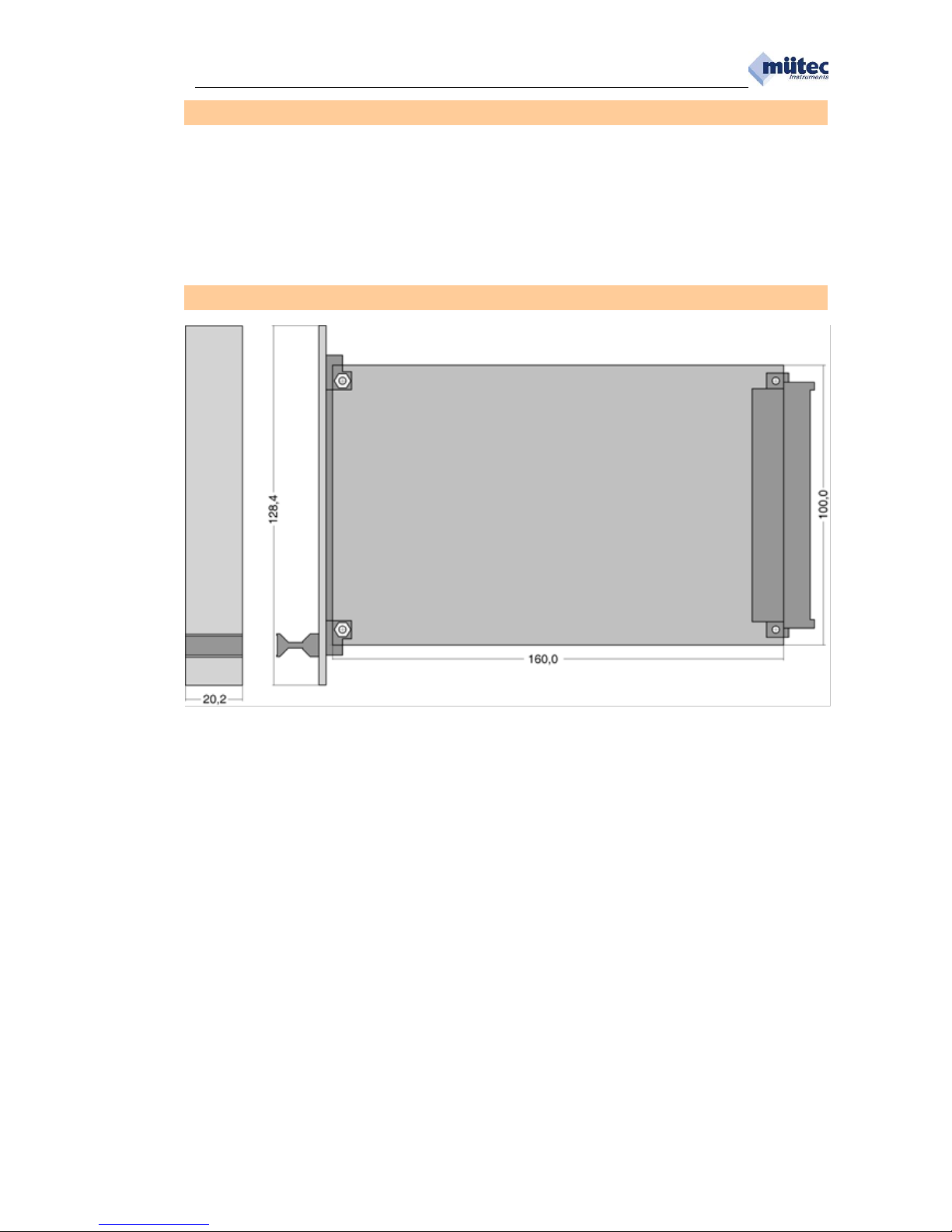
DIMENSIONS OF THE MTP200ia-E
Page 17

02/2014
_____________________________________________________________________________________________________________________
17
5.1. Configuration protocol
A configuration dated protocol can be created for the MTP200 using the WINSMART® program with the
command Print configuration.
The TAG number, unit-specific device address, serial number and version number are logged as identification
in the unit software.
The extensive comments saved in the device, with a maximum of 2000 ASCII characters, are printed out in a
protocol with the first 60 characters.
All parameters for input, output and the alarm settings are listed in a table. In addition, the permissible
tolerance deviations of the measuring input, analogue output and user for the monitoring circuit are listed in a
table.
MÜTEC GmbH Configuration protocol for MTP200 07-05-2012
TAG No.: Rack45-18 Software version: 4.0
Serial No.: 08_245 Device address: 1
INPUT
Sensor type
……………………………………………………………….
PT-100 3-wire-switching
Measuring range beginning
…..………………………………………….
0
°C
Measuring range ending
…………………………………………………
200
°C
Filter time
.............................................................................................
0.5
s
OUTPUT
Area beginning
……….……………………………………………………
4.00
mA
Area ending
…………..……………………………………………………
20.00
mA
MIN-limit
……………..……………………………………………………
3.60
mA
MAX-limit
…………..……………………………………………………..
20.50
mA
Alarm value
………..………………………………………………………
21.00
mA
Filter time
………..……………………………………………………….
0.5
s
ALARM 1
Alarm type
……………………………………………………………..…
MIN-Alarm
Function
……………..……………………………………………………
zero signal current
Alarm value
…………..……………………………………………………
40
°C
Hysteresis
…………..………………………………………………….…
1.0
%
Alarm delay
…………..……………………………………………………
0.5
S
ALARM 2
Alarm type
..……………………………………………………………….
MAX-Alarm
Function
……………………………………………………………………
zero signal current
Alarm value
..………………………………………………………………
160
°C
Hysteresis
..……………………………………………………………….
1.0
%
Alarm delay
..………………………………………………………………
0.5
s
ALARM 3
Alarm type
…………………………………………………………………
MIN-Alarm
Function
……………………………………………………………………
zero signal current
Alarm value
……………………………..…………………………………
20
°C
Hysteresis
…………………………………………………………………
1.0
%
Alarm delay
………………………………………………………………..
0.5
s
ALARM 4
Alarm type
…………………………………………………………………
MAX-Alarm
Function
……………………………………………………………………
zero signal current
Alarm value
……………………………..…………………………………
180
°C
Hysteresis
…………………………………………………………………
1.0
%
Alarm delay
………………………………………………………………..
0.5
s
Time window for rate of change alarm
…………………………………
4
s
MONITORING MEASURES
mV-Input - maximum tolerance
………………………………………
+/- 1.0
%
Resistance Input - maximum tolerance
…………………………………
+/- 1.0
%
Analog Output - maximum tolerance
+/- 1.0
%
OUTPUT
Fault sources:
Analogue Output
Relay 1
Relay 2
Logic 1
Logic 2
8-Bit-Processor
Alarm value
on
active - -
Supply/8-Bit-uP
Alarm value
on
active - -
Supply/16-Bit-uP
Alarm value
on
active - -
mV-Measuring circuit
Alarm value
active
active
on
on
Resistance circuit
Alarm value
on
active
on
on
Output signal
Alarm value
active
active
off
off
Sensor / wire break
Alarm value
on
active
off
off
RAM-/EPROM-memory
Alarm value
on
active - -
EEROM-memory
Alarm value
on
active - -
Relay 1 - 3
Alarm value
on
active - -
Page 18
02/2014
_____________________________________________________________________________________________________________________
18
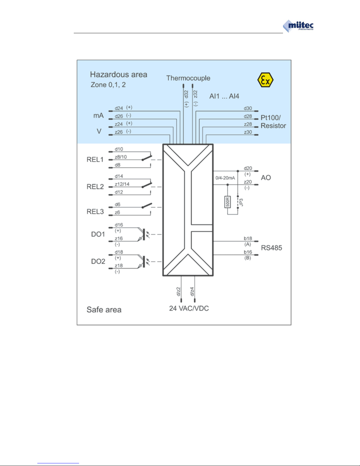
5.2. Basic Circuit Diagram
Page 19
02/2014
_____________________________________________________________________________________________________________________
19
5.3. General view
Page 20
02/2014
_____________________________________________________________________________________________________________________
20
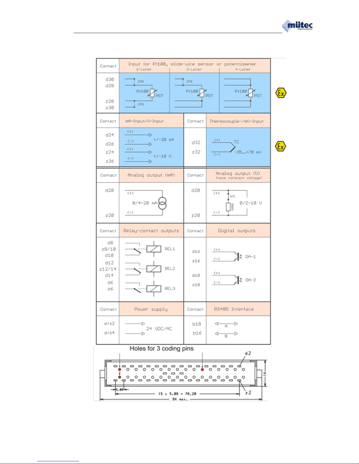
5.4. Contacts and female multipoint connector’s coding
Page 21

02/2014
_____________________________________________________________________________________________________________________
21
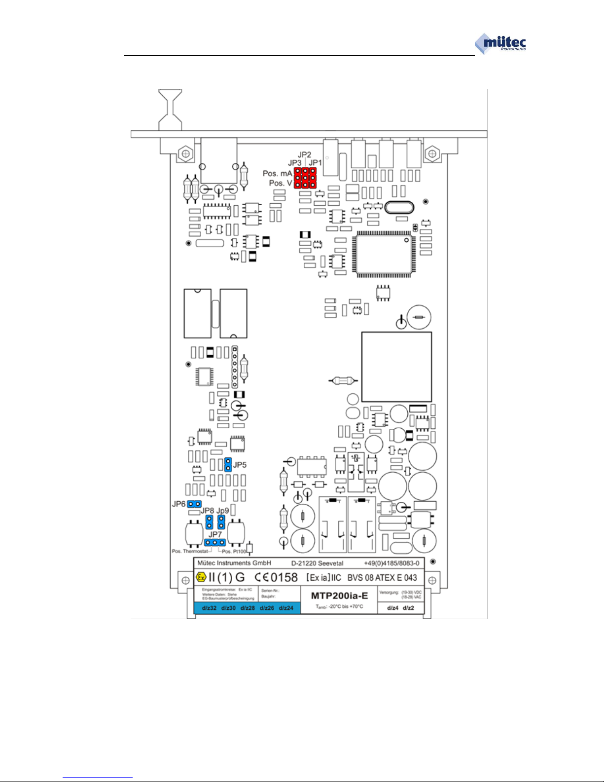
5.5. Jumper-settings
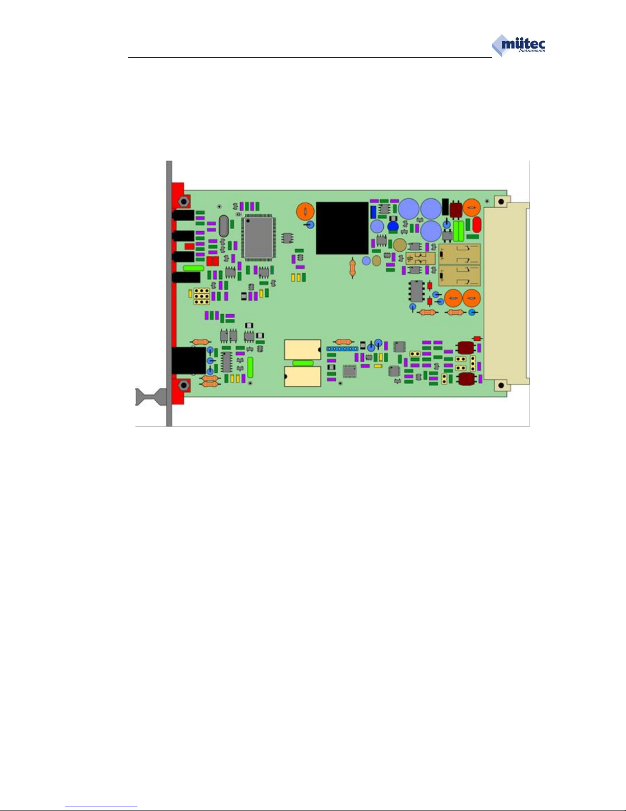
Jumper JP1 – JP3:
Via Jumper JP3 the analog output is switched from constant current (mA) to voltage (V).
At the same time, the Jumper JP1 and JP2 have to be reconnected, thereby it is possible
to measure the selected output signal at the test socket in the front.
Jumper JP5, JP6, JP7, JP8 and JP9:
Measuring input for:
JP-5
JP-6
JP-7
JP-8
JP-9
Voltage (V)
X X X* X X
Voltage (mV)
X
--
X* X X
Current (mA)
X X X* X X
Thermocouple
with internal TVG
X
--
X* X X
Thermocouple
with external TVG
X
--
-- X X
Thermocouple
with thermostat
X
--
X** X X
Pt-100/2- wire-circuit
X X -- X X
Pt-100/3- wire-circuit
X X -- X --
Pt-100/4- wire-circuit
X X --
--
--
Potentiometer/0-600
2-wire-circuit
X X -- X X
Potentiometer/0-600
3- wire- circuit
X X -- X --
Potentiometer/0-600
4- wire- circuit
X X --
--
--
Potentiometer/0-5000
2- wire- circuit
-- X -- X X
Potentiometer/0-5000
3- wire- circuit
-- X -- X --
Potentiometer/0-5000
4- wire- circuit
-- X --
--
--
X* = JP7 in Position Pt100, X** = JP7 in Position Thermostat
X = Jumper closed
-- = Jumper opened
After pressing the button JUMPER FINDER in the WINSMART’s masks Measuring
Input and Analog Output, the position of the jumpers is shown according to the
component diagram section.
Page 22
02/2014
_____________________________________________________________________________________________________________________
22
6. Configuration program
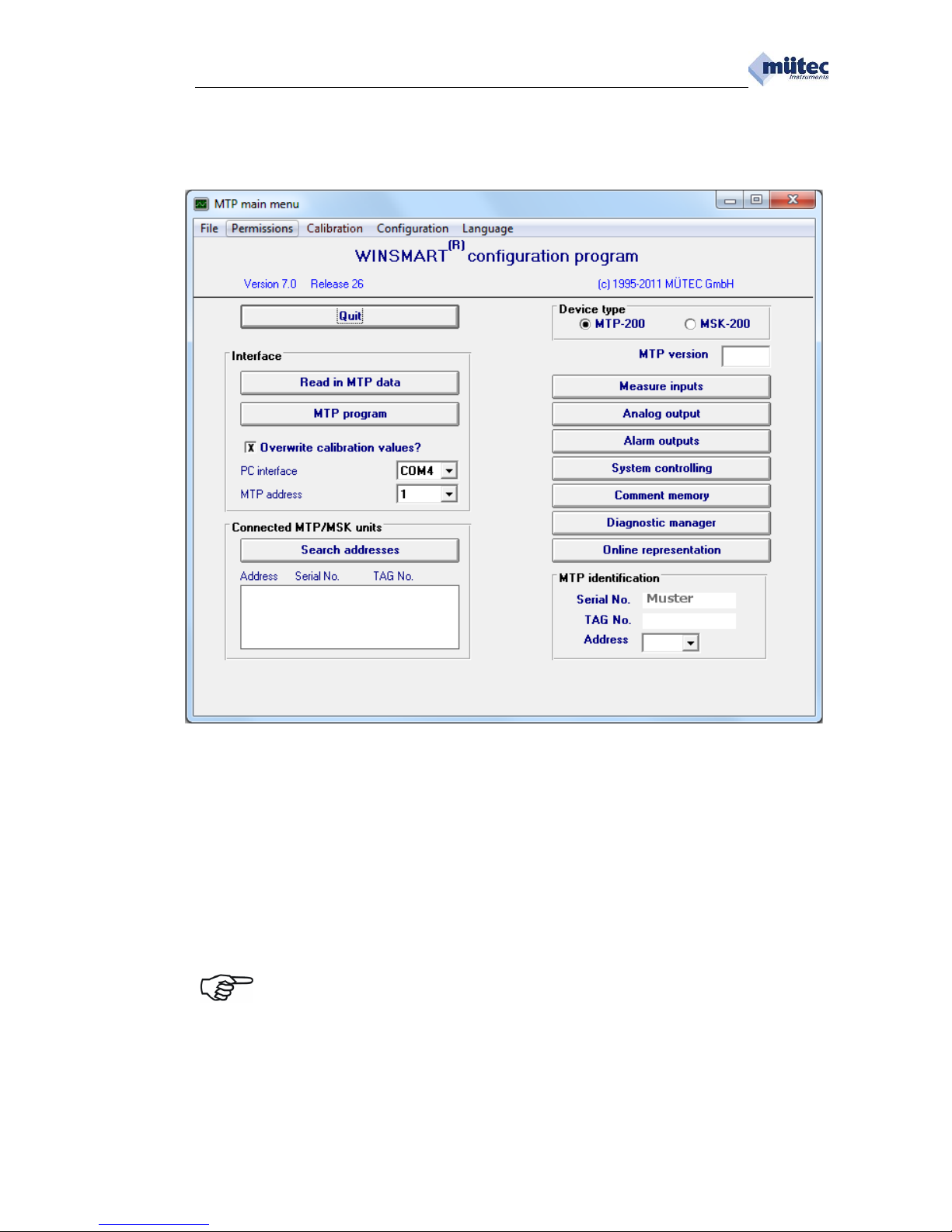
The illustration above shows the opening screen of the WINSMART configuration program for the MTP200
and MTP200 with the corresponding version and release number of the program.
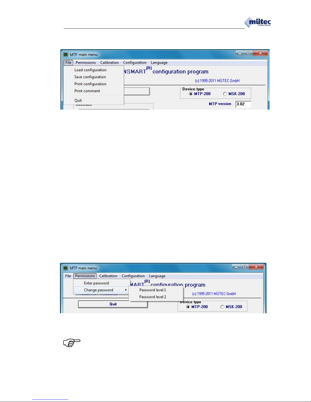
The command File in the menu bar is used to access existing configuration files and for saving and printing of
the current configuration. Two of the three operating levels, which can be accessed by using the command
Permission, are secured by passwords. The operating level for calibration of measure inputs and analogue
outputs has a special importance. Only after password input and the command Calibration it is possible to
access one of two masks.
To communicate with the WINSMART program it is necessary to enter the COM address in the field PC
Interface and MTP address (left area of the screen in the section Interface). A device with unknown address
can be identified by using the function Search address. After finding the device address the Serial-No. and
TAG-No. will be shown.
Administration of access rights for three operating levels secured by codes and calibration for the measuring
input and analogue output. The WINSMART configuration program supports both MTP200 and MSK200.
. For information about the MTP200, which will not be covered in the following description,
refer to the existing MTP200 manual.
The buttons arranged below offer access to configuration and parameter settings for the MTP200 input and
output. The desired settings for the SIL2 monitoring circuit can be made in the relevant screen with the button
System Controlling. The Diagnostic Manager reports the status of the device and also saves faults that
arise even briefly. The online display offers the user a precise analogue and digital illustration of the
measured input magnitudes and output signals.
Page 23
02/2014
_____________________________________________________________________________________________________________________
23
6.1. Menu bar and commands
6.1.1. File Load configuration
The MTP200 parameter set saved in a file with extension *.MTP on the hard drive is loaded into the Windows
configuration program. Thus a parameter set already created and saved can be copied fast and reliably into
other devices, if the same configuration is needed for these.
6.1.2. File Save configuration
The MTP200 parameters of the configuration program are saved on the hard drive in a file with the extension
*.MTP and archived. For later duplication into another MTP200, the file must only be loaded in the set-up
program and transferred in the MTP200 with the command MTP program.
6.1.3. File Print configuration
All MTP200 parameters of the configuration program and the first 60 characters of the comments are printed
out as a dated protocol and the device characteristic data on a DIN-A4 page. The printer available under
Windows is used. The character font and print format are fixed and cannot be changed by the user.
6.1.4. File Print comment
The extensive comments saved in the device as dated protocol with a maximum 2000 ASCII characters and
the device characteristic data are printed out on a DIN-A4 page. The printer available under Windows is used.
The character font and print format are fixed and cannot be changed by the user.
6.1.5. File Quit program
The message Program quitting appears with a request for confirmation by OK or Cancel.
6.1.6. Access rights Enter password
After the corresponding password is entered, entry is enabled to the otherwise locked functions of the
configuration program.
The configuration program is divided into 3 access areas:
The open program area contains no settings and so is always accessible.
Password level 1 contains all parameter settings.
Free input to this level is secured only after password assignment
Password level 2 contains calibration excluding configuration. This input is secured by a password assigned
by the manufacturer (5180). Of course this password can be replaced with a new one by the user. Furthermore
password 2 gives access to all parameters and functions of the device.
Page 24
02/2014
_____________________________________________________________________________________________________________________
24
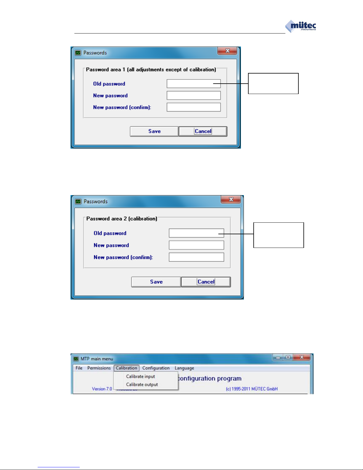
6.1.7. Access rights Change password Password level 1
Password level 1 covers all parameter settings of the MTP200 and is only enabled for authorised personnel
(e.g. maintenance staff, service technician) to access all configurable settings.
The password may have a maximum of 20 alphanumeric characters and is entered and saved in the
corresponding fields as in the screen.
6.1.8. Access rights Change password Password level 2
Password level 2 secures parameter settings for calibration and the function Overwrite calibration values. It
is reserved exclusively for technicians with special knowledge of the device and its functions.
Password level 2 is secured by a password (5180) assigned by the manufacturer.
A newly assigned password may have a maximum of 20 alphanumeric characters and is entered and saved
according to the indicated fields as in the screen
6.1.9. Calibration Calibrate input PT-100
A calibration is only necessary for the analogue in- and output signal. Before calibration the parameter set
must be read from MTP200 into WINSMART-program. In addition, you have to select the resistance
measurement input for the Pt 100 calibration (see section 10.1 Measurement inputs).
No entry with the
first assignment of a
password!
Enter 5180 for the
first change of the
pre-occupied
password!
Page 25
02/2014
_____________________________________________________________________________________________________________________
25
The JP8/JP9 jumpers define the Pt 100 input configuration as a 2-wire, 3-wire or 4-core circuit. For the
resistance measurement, too, only one valid set of parameters can be stored in the MTP200. For this reason
you should carry out recalibration after every change in the Pt 100 input configuration whenever maximum
accuracy is required.
Every calibration has to take place in 2 steps. The calibration points can be freely selected within the
characteristic curve range available, but we recommend that you place the calibration points within the
measuring range for a high degree of accuracy. For the 1st calibration procedure the Pt 100 simulator at the
MTP200 input is set to the desired temperature value, and the command to Read in is triggered. The
messages Measurement running and finished appear one after the other in the mask. After
acknowledgement with OK the 1st calibration value is accepted and shown analogously as a bar in the mask.
The proportional representation in the bar chart serves as a check and helps to avoid calibration errors.
Same calibration values for the 1st and 2nd calibration point same bar lengths no
measured value illustration possible output jumps!
Next, the second calibration point is simulated with the measuring input mA value, confirming calibration with
Read and finalized with OK.
For monitoring the supply circuits at the contacts d/z30 and d/z32 a reference level at 20mA is needed, which
can be simulated easily with a current sink. The voltage value is recorded by clicking the button Read and is
figured in bar units for monitoring.
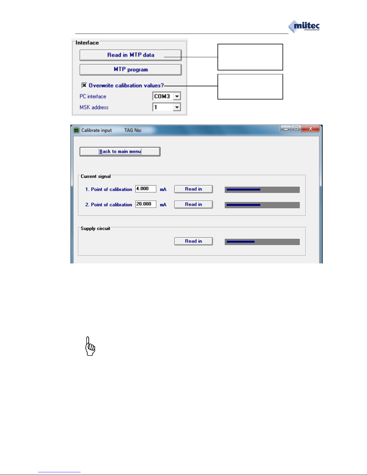
Finally the calibration values needs to be transferred to the MTP200. Therefor mark the box Overwrite
calibration values? with a cross and click the button MTP program. The transfer starts and the question
Existing parameters will be overwritten. Continue anyway? appears in the screen. This procedure is
started with OK and the next message reads: Transferring parameters. A final OK completes the procedure
and the calibration.
May be implemented only
for the actualization of the
calibration parameters
contained in the MTP200!
Before beginning of the
calibration the parameters
from the MTP200 must be
read in!
Page 26
02/2014
_____________________________________________________________________________________________________________________
26
6.1.10. Calibration Calibrate input Thermocouple
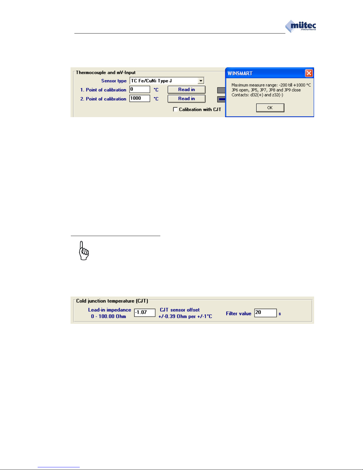
The set of parameters from the MTP200 has to be read in before beginning the calibration. For calibration of
the thermocouple measurement input place the jumpers according to the specifications in the WINSMART
mask for activation of the thermocouple measurement input (see section 10.4 Measurement inputs).
For the 2-point calibration you can freely select the calibration points within the characteristic curve range. In
the case of high accuracy requirements, we always recommend the required measuring range as the
calibration range. Before starting calibration, you have to clarify the question of whether or not to take the
temperature reference junction (TRJ) into account, i.e. should the ambient temperature measured by the TRJ
apply as the reference temperature or 0°C. For calibration with the TRJ you have to mark the box Take TRJ
into account in the calibration in the mask.
The calibration procedure begins with simulation of the temperature value for the 1st calibration point and entry
of the command Read in. The messages Measurement running and finished appear one after the other in
the mask. After acknowledgement with OK the calibration value is accepted and shown analogously as a bar
in the mask. The proportional representation in the bar chart serves as a check and helps to avoid calibration
errors (equal calibration values equal bar lengths measured value display not possible output jumps
back and forth. The same procedure is repeated for the 2nd calibration point. Transfer of the calibration values
to the MTP200 marks the conclusion of the calibration procedure. For this mark the box Overwrite calibration
values in the main MTP menu, and start the transfer with the button Program MTP (see screen area
Interface). The message Existing parameters will be overwritten. Still continue? appears in the mask. Use
OK to start the process; the next message is: Transfer parameters. A last OK ends the entire transfer
process and thus the calibration as well.
Temperature reference junction (TRJ)
The TRJ calibration requires a correctly calibrated resistance input as a 2-wire circuit in a
range from 0 – 50 Ω.
The internal TRJ consists of a Pt 100 sensor placed in the terminal block so that the KL19 + KL20 are not
necessary. The terminals KL19 + KL20 are used for connection of an external Pt 100 sensor in a 2-wire circuit
only in the case of an external TRJ. Then you have to use a standard terminal block with the terminals KL17 to
KL20. A more or less substantial error in the cold junction temperature results from the lead resistance of an
internal/external Pt 100 sensor.
There are two options for error correction:
One is to enter the measured resistance value of the lead directly in the mask. The second option is to correct
the sensor error as well as the lead resistance. In this case the read-off TRJ temperature value of the online
mask and a precise measured value of the cold junction temperature are required. You can calculate the lead
resistance for the TRJ calibration via the resistance gradient of the Pt 100 sensor at 0.39 /C and enter it in
the mask.
Example 1:
TRJ-value in the online-mask
=
27.40
°C
Measured cold junction temperature
=
22.80
°C
--------------------------------
ΔT = (27,4 - 22,8) °C
=
4.60
°C
Load resistance = 0.39 Ω/°C x 4.6 °C
=
1.79
Ω
Page 27
02/2014
_____________________________________________________________________________________________________________________
27
Example 2:
TRJ-value in the online-mask
=
24.10
°C
Measured cold junction temperature
=
25.00
°C
--------------------------------
ΔT = (24,1 - 25,0) °C
=
-0.90
°C
Load resistance = 0.39 Ω/°C x (-0.9) °C
=
-0.35
Ω
The TRJ calibration has to be carried out while using an external and an internal Pt 100
sensor.
A filter of the 1st order is parameterized by means of the filter time of up to 999 seconds for the temperature
reference junction (TRJ). The greater the filter time, the greater the damping of temperature fluctuations.
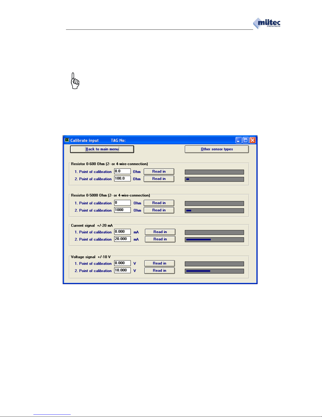
6.1.11. Calibration Calibrate input Resistance, Current and Voltage
After reading in the set of parameters from the MTP200, you have to activate the resistance measurement
input for the 2-wire or 4-wire circuit as the active input by using the jumpers (see section 10.4 Measurement
inputs).
Resistance input for 2- or 4-wire-circuit:
The input is defined as a 2-wire or 4-wire circuit using the jumpers JP8/JP9, and the calibration is defined
accordingly on this basis. If the input configuration is changed later, the calibration should be repeated for
maximum accuracy. For the 2-point calibration within the characteristic curve range you can freely select the
calibration points, but we always recommend using the required measuring range for the calibration range.
The calibration procedure is the same as for a thermocouple input (10.1.10).
Current input:
A bi-directional mA signal can be measured with the mA input at KL13/14. The calibration points can thus be
placed in a range from -20 mA to +20 mA. The 2-point calibration takes place as already described.
Voltage input:
A bi-directional V signal can be measured with the V input at KL15/14. The 2 calibration points, placed in a
range from -10 V to +10 V, are recorded in the same way as previously documented.
Page 28
02/2014
_____________________________________________________________________________________________________________________
28
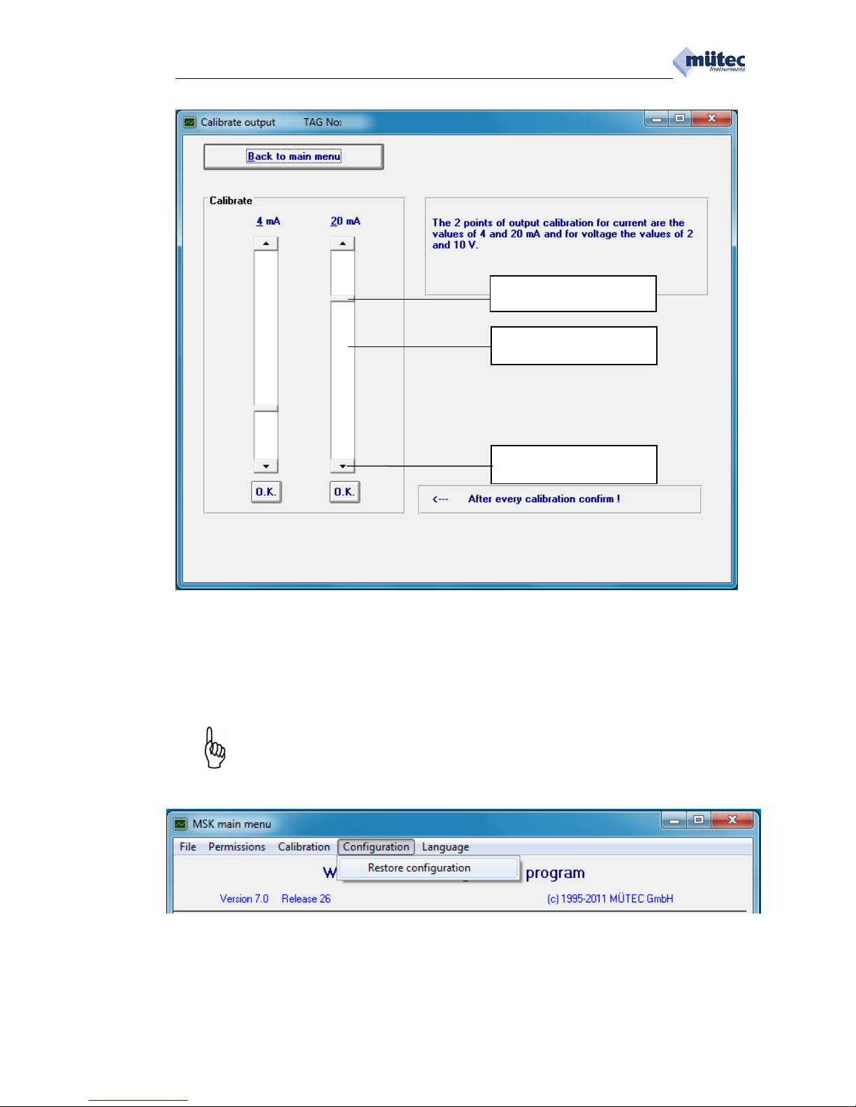
6.1.12. Calibration Calibrate output Current or voltage
Before beginning each calibration, the parameter set must be read from the MTP200. A 4½-place digital circuit
analyser is connected to the MTP200 output terminals and the output signal is adjusted with the jumper 3 for
constant current or voltage.
The calibration screen contains 2 V and 10 V for voltage output or 4 mA and 20 mA for current output marked
by sliding controls. The alignment procedure for the coarse, exact and final adjustment is free selectable and is
confirmed with the OK button. After comparing the ZERO and SPAN value the determined calibration
parameters need to be transferred to the MTP200 by clicking MTP program and Overwrite calibration
values
The output signal 0/2-10 V is generated by a constant current 0/4-20 mA, which runs over a
resistive shunt of 500 Ω, assuming that JP1…JP3 is set on “V”.
Therefore a voltage results in a fault of 1 % in the case of a burden resistance of 50 kΩ,
which is completely eliminated by recalibration.
6.1.13. Restore configuration
The Configuration of the device contains all MTP200 values and is automatically saved as an entry under
Windows with Read MTP data. Thus each device can be reset to the original operating condition with the
command Restore configuration, under the condition that both procedures are executed at the same PC.
After the command Restore configuration, all values in the Windows screens and in the MTP200 are reset
with the original data set. This procedure offers the convenient option to reset a device provided with
erroneous calibration values or reset parameters with manufacturer values.
Exact adjustment by clicking
these surfaces!
Final attitude by clicking
these Buttons!
Coarse adjustment by shifting
the buttons!
Page 29
02/2014
_____________________________________________________________________________________________________________________
29
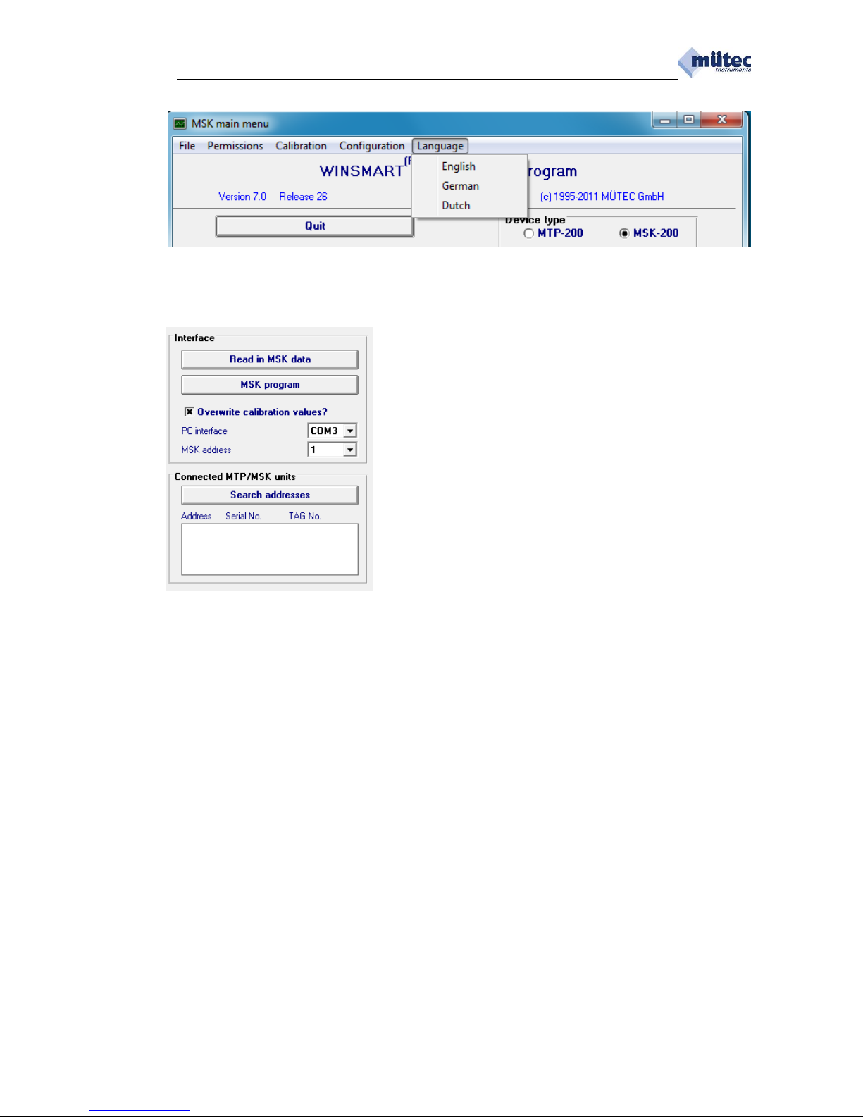
6.1.14. Language English, German, Dutch
There are three language versions in the WINSMART program selectable.
6.2. Interface and connected devices
Communication between the MTP 200 and the Windows PC is
made by the front-side COM/RS232 or RS485 interface at the
contacts of mounting rail bus connector.
By plugging on the COM-cable at the front socket, the change
over from RS485- (offline) to COM-interface (online) is made
automatically.
After disconnection of COM-connection, the RS485 interface is
reactivated.
The RS232 interface and the RS485 interface are galvanic
separated from analog output, auxiliary power and all other
circuits parts.
6.2.1. Reading MTP data
The command Read MTP data starts a data transmission of the entire parameter set of the MTP200 to the
configuration program. The interface connection will only work if the correct entries are made in the screen for
the serial COM interface (COM1 to COM20)) and MTP address (1-255). Should the MTP address be unknown
or not marked on the device, then the unknown address can be determined with the command Search for
addresses. After conclusion of the correct transmission, the message Reading parameters appears and
must be confirmed with OK.
6.2.2. Programming MTP data
The command Program MTP transfers the parameter set contained from WINSMART program to the
MTP200. After command input the following message appears on the screen: Existing parameters will be
overwritten. Continue anyway?
With OK the procedure is started, after which the confirmation appears Transferring parameters and is
confirmed with OK to complete the transmission.
6.2.3. Overwriting calibration values
If the box for Overwrite calibration values is selected in the input screen, the calibration parameters for
analogue input or analogue output can be transferred to the MTP200 with the command Program MTP,
possibly updated in the configuration program.
The message then appears in the screen:
Existing parameters will be overwritten. Continue anyway?
The procedure is started with OK and the next message reads:
Transferring parameters. A final OK completes the transmission
6.2.4. PC interface
The addresses COM1 to COM20 are selectable.
Page 30
02/2014
_____________________________________________________________________________________________________________________
30
6.2.5. MTP-address
The MTP address setting regulates communication over the interface with the receiver. The PC, as the master
device, sends a transmission with the device address that is read with each MTP200 (slave) by using the COM
interface in case of an individual compound or using the RS485 interface in case of a multidrop connection.
Only the MTP device with the set address communicates to the master. Consequently, MTP devices with same
address may not be connected.
6.2.6. Connected MTP devices Search for addresses
A search function lists the connected and addressable MTP devices with their specific characteristic data such
as address, serial number and TAG number.
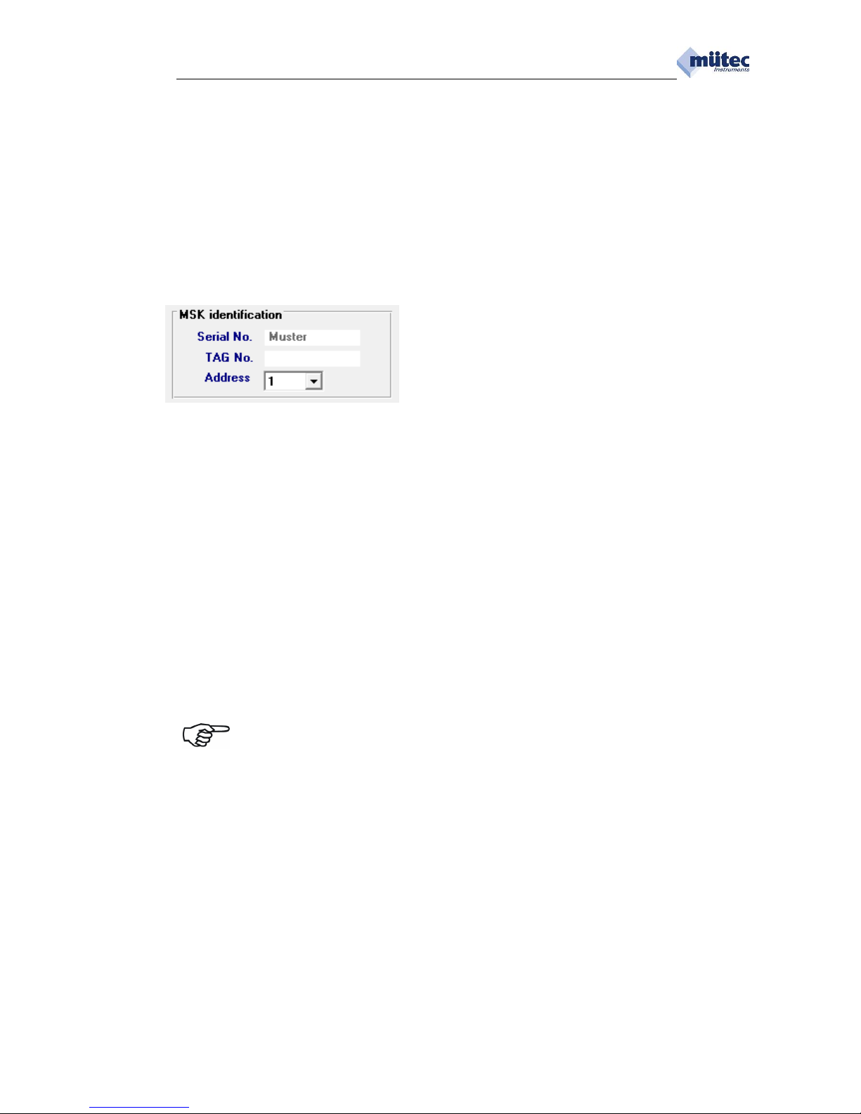
6.3. MTP identification
6.3.1. Serial No.
The serial number is a 8-digit manufacturer-specific unit number ensuring clear identification for each
MTP200. It consists of a date code (year + calendar week) and a sequential number.
The serial number cannot be edited!
6.3.2. TAG No.
The TAG number can contain maximum 8 alphanumeric characters as user-defined device identification.
6.3.3. Address
For the device address, a maximum entry of 3 digits in the address field is set. Setting a device address
involves:
1. Selection of device address with max. 3 digits in the MTP identification field;
2. Setting of the current device address in the Interface field;
3. Execute the Program MTP command and confirm;
4. Read back the MTP data with the command Read MTP data (after finishing these actions, the
new device address is indicated in the field MTP identification).
For a successful device connection the 3 digits address in the MTP identification field and
in the Interface field has to be correspond with the device address.
Page 31
02/2014
_____________________________________________________________________________________________________________________
31
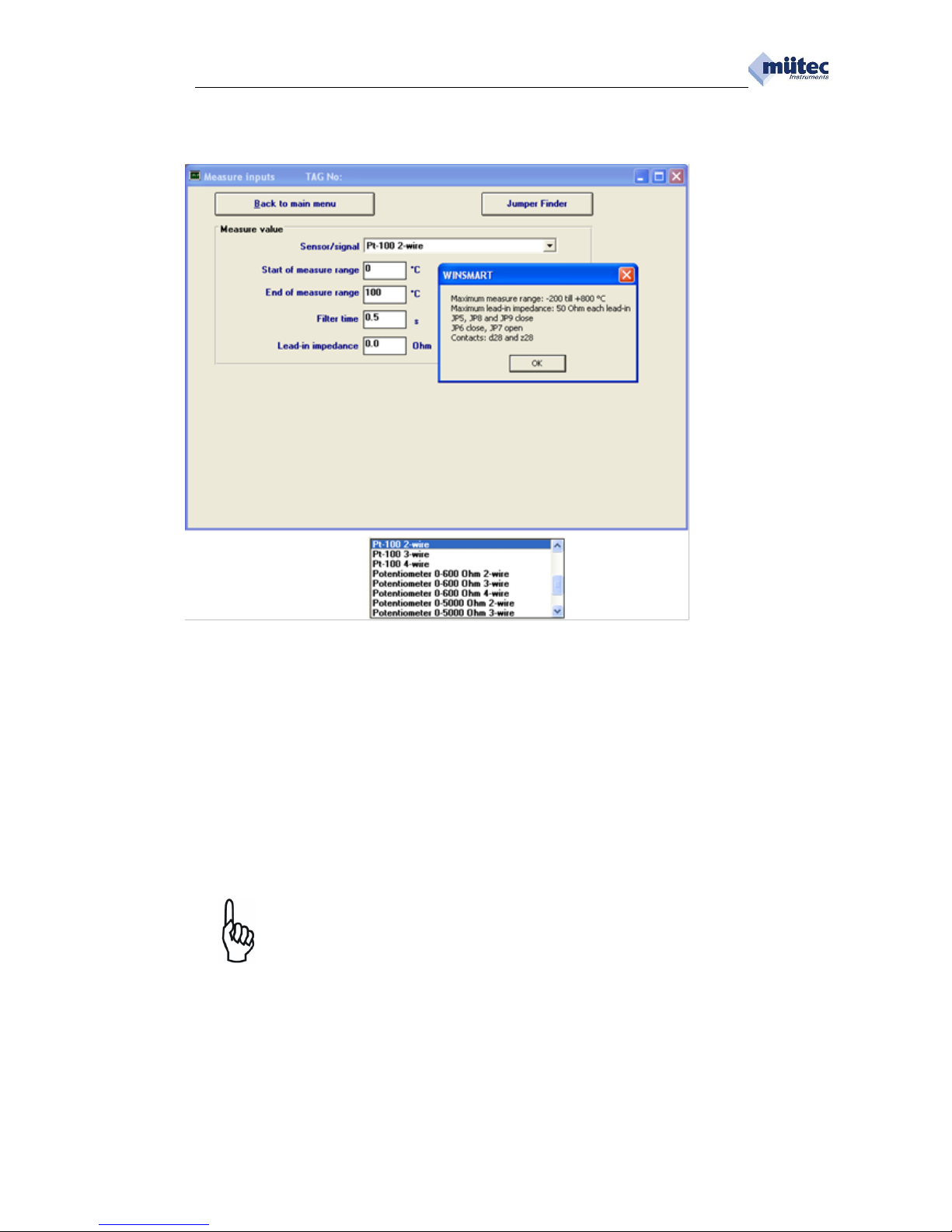
6.4. Measuring input
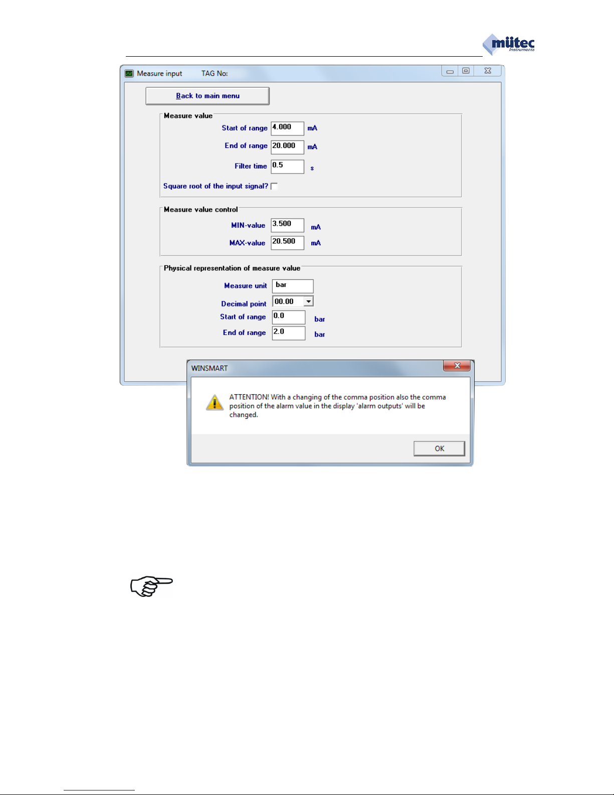
All available sensor types and measuring signals for selection and parameterization are listed in the mask of
measurement inputs. Of the four different measurement inputs at the terminals of the MTP200, only one can
be activated and parameterized in each case. After the sensor type or measured variable has been specified,
a window appears with the information for the:
1. Maximum available measuring range
2. Jumpers to be opened/closed
3. Terminal assignment for measurement input
A filter time of minimum 0.1 to maximum 99.9 seconds defines a first order filter for the measure signal. With a
larger filter time, the measured value is more damped.
For compensation of the lead resistance in the case of a resistance sensor with a 2-wire connection you can
enter the resistance value directly in the mask. The total value of the feed and return circuit resistance may not
exceed 100 ohms.
There in the mask measure input specified measuring range (e.g. 0.000 to 2.000 bar)
complies 0 to 100 % of range for the limit value monitoring. The minimum adjustable limit
value is 0.000 bar and the maximum 2.000 bar.
For a correct parameterization of MTP200 make adjust first the measuring range and second
the limit values. If you changed later the measuring range, always check the limit value
alarms as well.
Page 32
02/2014
_____________________________________________________________________________________________________________________
32
For standardized measurement signals further entries must be made in rubric Physical representation of
measure value. They are needed for a representation in the online mask.
Unit:
Physical unit of measured variable (bar, °C, K, etc.)
Decimal point:
None, 1, 2 or 3 places after the decimal point
Start of range:
Physical measure value at start of range
End of range:
Physical measure value at end of range
MIN value:
Minimal measure value for initiation of fault alarm
MAX value
Maximal measure value for initiation of fault alarm
For a correct limit value control must be placed the minimal measure value and the maximal
measure value out of the range from the measured range because an exceedance of this
limits triggers the maintenance alarm. Same values for area limit-MIN and area limit-MAX
are not allowed and lead after the programming of the MTP200 for a maintenance alarm!
Page 33
02/2014
_____________________________________________________________________________________________________________________
33
6.5. Analogue output
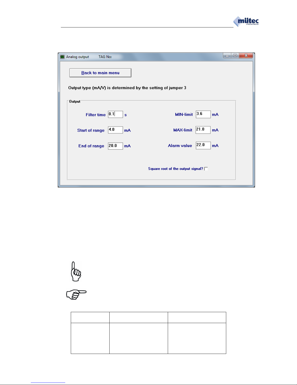
The Filter time of minimum 0.1 seconds up to maximum 9.9 seconds defines a first order filter for the output
signal. The analogue value is more strongly dampened with increasing filter time.
For analogue output the illustration range is set by the definition of values for Start of range and End of
Range.
This applies during voltage output amounting to a max. output range 0 - 11 V or with current output 0 - 22 mA.
Exceedance can be reliably prevented within the illustrated range by the input MIN limit and MAX limit of the
defined output range.
The Alarm value function defines a fixed value for analogue output. This is activated if a correct recording of
the measured value is no longer possible in the input due to a fault and is programmed in the screen for
System controlling with the function Alarm value for analogue output.
Square root extraction can be realized by activating the button Square root of the output signal.
All adjustments made in this mask are stored and activated by the command Program MTP.
In principle it is possible to register an alarm value of 0. In this case the breakage monitoring
at mA-output can not differentiate between alarm value and line break. The result is a
constant switching of relay-3.
During voltage exit neither a short circuit nor an interruption of the connection to the burden
can be recognized!
mA-values for an output signal without and with square root extraction:
Input signal
Output signal
without square root extraction
Output signal
with square root extraction
0 %
4.00 mA
4.00 mA
25 %
8.00 mA
12.00 mA
50 %
12.00 mA
15.31 mA
75 %
16.00 mA
17.86 mA
100 %
20.00 mA
20.00 mA
Page 34
02/2014
_____________________________________________________________________________________________________________________
34
6.6. Alarm outputs
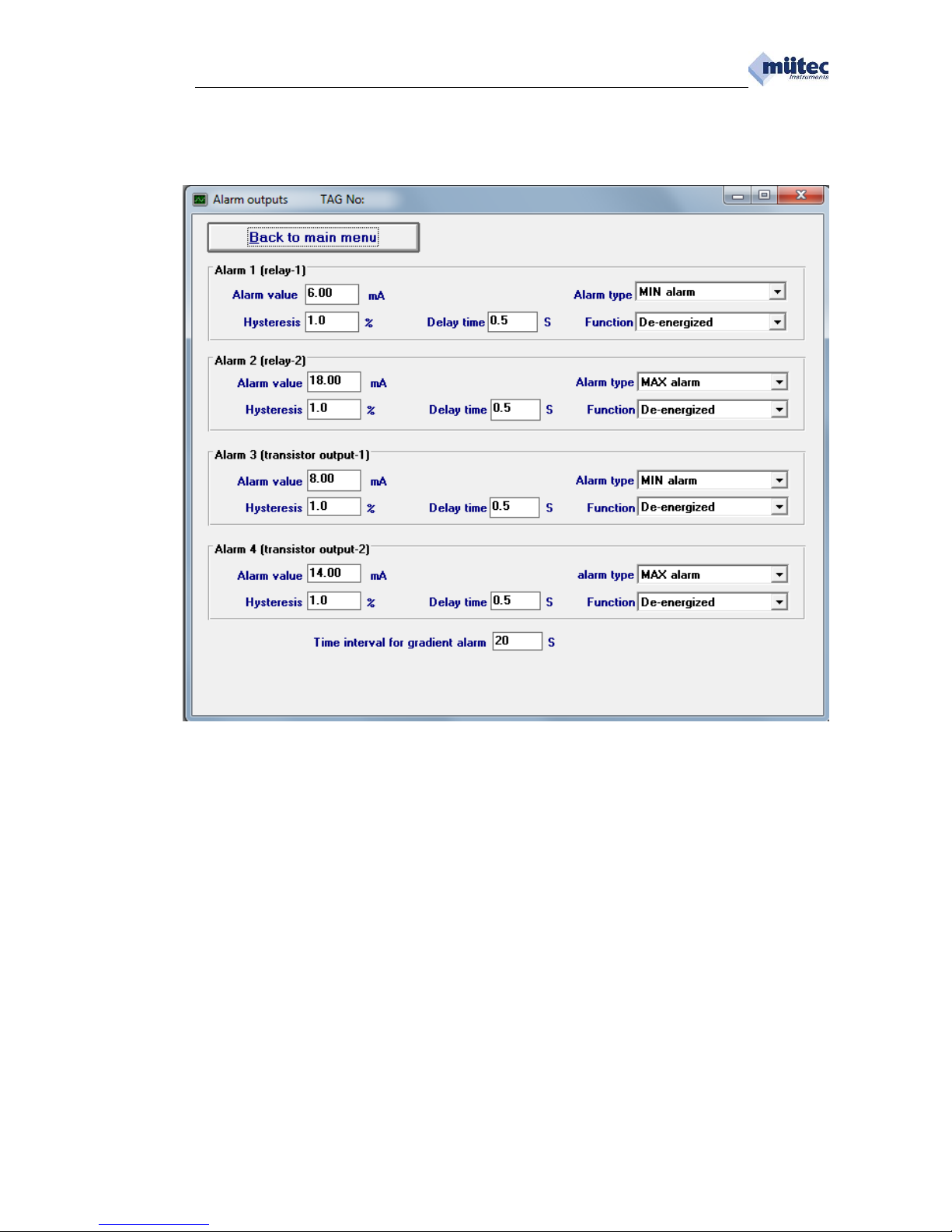
The mask for the alarm outputs enables quick setting of all parameters due to the clear display of the three
alarms available (2x relay contact output, 1x transistor output).
A value between 0 and 99.9% of the measuring range is assigned to each alarm value hysteresis. For a
measuring range of 500°C a temperature level hysteresis of 2% corresponding to 10°C, with an activated
MAX alarm of up to 400°C is only reverse with a temperature level of < 390 °C. An alarm delay up to a
maximum of 9.9 seconds guarantees that briefly exceeded alarm values do not activate the alarm.
Available alarm types:
MAX alarm with rising measured value
MIN alarm with falling measured value
Gradient MAX alarm with rising and falling function line
Gradient MIN alarm with rising and falling function line
Available alarm functions:
Open circuit principle: in good status the relay is not under current
Closed circuit principle: in good status the relay is under current
No function: alarm output is switched off
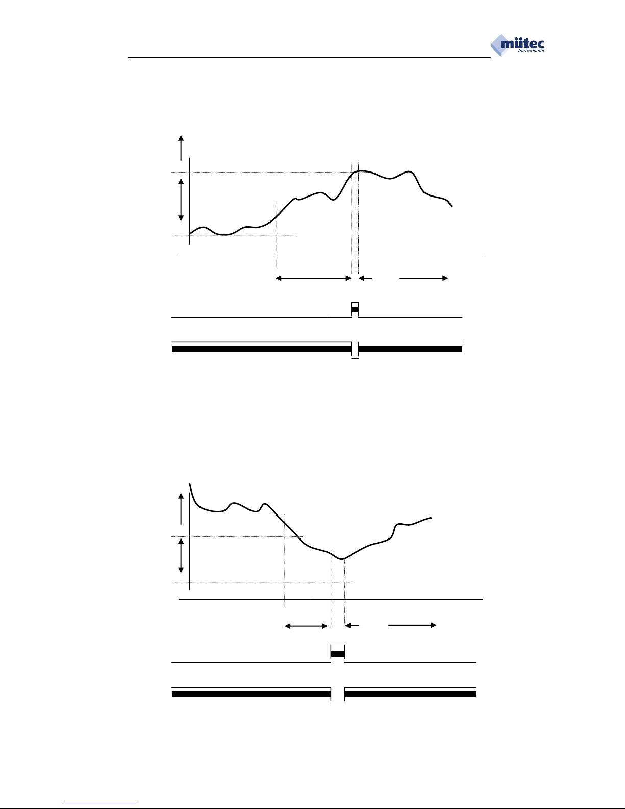
The gradient alarm needs a time interval as an additional parameter. It shows a time period between 0 and
9999 seconds, in which 20 samples are collected and used as the basic for the gradient alarm calculation.
Alarm value and alarm type are available in the online mask. Activated limiting value alarms are marked in red.
Page 35
02/2014
_____________________________________________________________________________________________________________________
35
6.6.1. Differentiated gradient alarm and the parameter settings
1. Example: Alarm value = 40 °C
Alarm type = Gradient-MAX + MIN-alarm
Time interval = 60 s (20 samples in 60s)
Temp
(°C)
40
Start 60 3 Time (s)
MAX-alarm
MIN-alarm
Every time interval contains 20 samples. The minimum pulse duration at
the alarm output is 0.05 x 60 s = 3 s!
2. Example: Alarm value = - 20 °C
Alarm type = Gradienten-MAX + MIN-Alarm
Time interval = 20 s (20 samples in 20s)
Temp
(°C)
20
Start 20 4 Time (s)
MAX-alarm
MIN-alarm
Every time interval contains 20 samples. The minimum pulse duration at
the alarm output is 0.05 x 20 s = 1 s!
Page 36
02/2014
_____________________________________________________________________________________________________________________
36
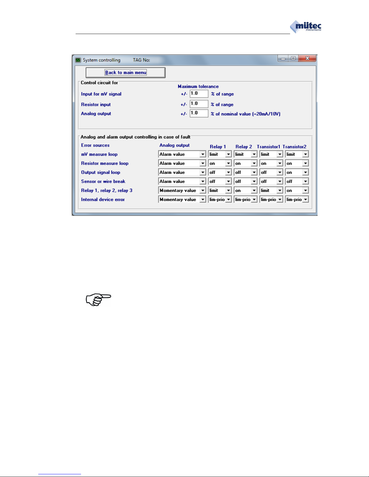
6.7. Monitoring conditions
A deviation fault between +/- (0.2 - 5.0) % is configured for mA measuring input and analogue output
respectively.
A tolerance beyond that activates an alarm for maintenance requirement by the relay 3 and a constant light
alarm LED on the front of the unit.
All faults in 6 fault sources, identifiable in the system, are summarized together in the screen. Each fault
source has optionally different settings for analogue output and the alarm outputs are to be assigned
determining behaviour in the fault event. The configuration for the alarm outputs (function, alarm type etc.)
takes place exclusively in the Alarm output screen, where defined alarm outputs are dimmed out no function
switched off and in the System controlling screen. In the fault event, the functions of analogue output and
alarm outputs defined are overlaid in the System controlling screen to ensure controlled behaviour.
Alarm outputs can be switched off by no function. Therefore they are not available in the
mask System controlling for maintenance requirement alarm.
No fault source is assigned to the 16-bit processor, because in the fault event for analogue output and alarm
outputs, no safe condition can be guaranteed. It is of course possible with hardware operation, that a failure of
the master processor could activate the SIL2 alarm for maintenance requirement.
Page 37
02/2014
_____________________________________________________________________________________________________________________
37
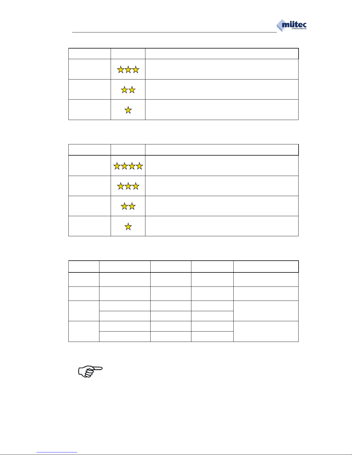
Analogue output in the event of fault:
Function
Ranking
Definition
alarm value
The output signal jumps to the alarm value defined in the
analogue output mask!
frozen value
The output signal remains at the value before fault
occurrence and is in an offline mode!
instantaneous
value
The output signal is updated and in online mode, but can
be erroneous!
Relay and transistor outputs in the event of fault:
Function
Ranking
Definition
on
The alarm output is switched on and the device required maintenance!
off
The alarm output is switched off!
lim-prio
The alarm output is switched off, only there is no limit value alarm.
limit
The alarm function is only the limit value monitoring!
Truth table for limit values and maintenance alarm:
Function
Limit value alarm
Maintenance
alarm
Alarm output
Notes
on x on
on
Only the fault alarm switched
the alarm output!
off x on
off
The fault alarm switches off
the limit value alarm!
lim-pro
x
on
off
The fault alarm switches off
the limit value alarm, but not
an existing limit value alarm!
on (alarm exists!)
on
on
limit
off
x
on
Only the limit value alarm
switched the alarm output
on
x
off
x=optional (on or off)
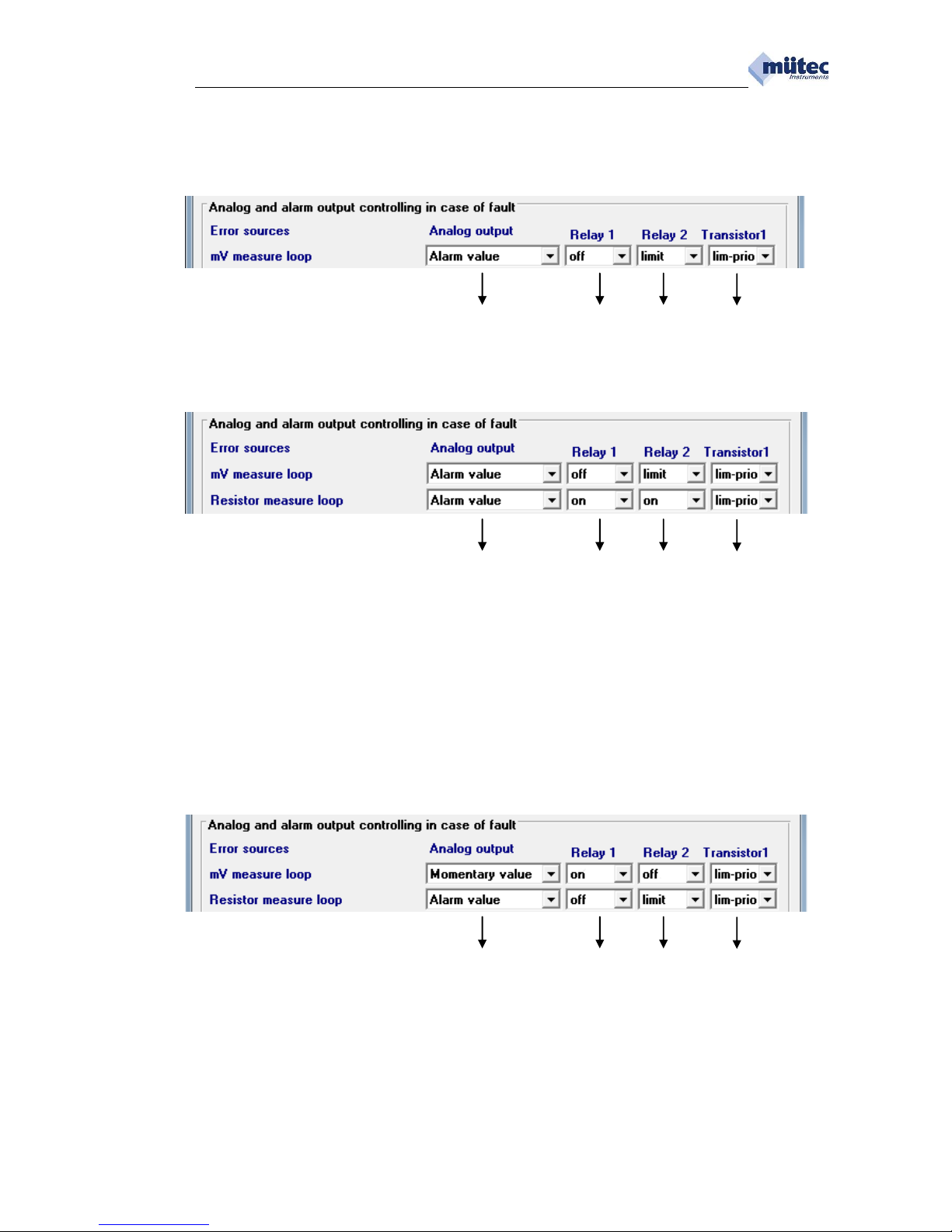
With a fault occurrence, the behaviour of the analogue output and alarm outputs correspond
to the parameterization in the mask System controlling without taking account of the
ranking. After the occurrence of a second fault the highest rank of the functions involved
determines the behaviour of the analogue output and alarm outputs.
(See some examples on next page)
Page 38
02/2014
_____________________________________________________________________________________________________________________
38
First example:
1. Fault: measure loop
Control of outputs:
Alarm value
off
limit
lim-prio
2. Fault occurs later: mA-Input
Control of outputs:
Alarm value
on
on
on
The behaviour of the outputs determined by the ranking:
Analogue output
stays on Alarm value
Relay 1
changes from relay off to relay on
Relay 2
changes from relay limit to relay on
Logic 1
stays on lim-prio
Second example:
2fault occur parallel
Control of outputs:
Alarm value
on
off
lim-prio
The behaviour of the outputs determined by the ranking:
Analogue output
changes to Alarm value
Relay 1
is switched on
Relay 2
is switched off
Logic 1
stays on lim-prio
Page 39
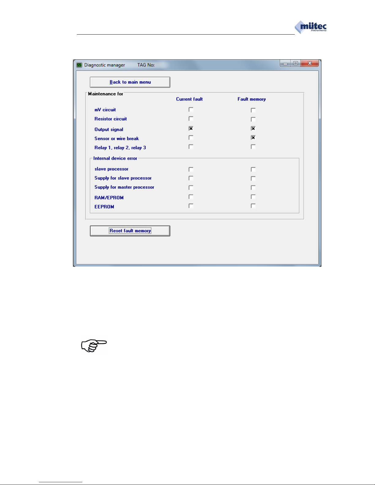
02/2014
_____________________________________________________________________________________________________________________
39
6.8. Diagnostic manager
The Diagnostic Manager records all occurred faults clearly inside and outside the MTP200. All 11 monitoring
functions are listed in a table and provided with windows for Current fault and Fault memory respectively.
Each current fault is signalled as a maintenance alarm by the continuous red lighted alarm LED and relay 3.
The diagnostic manager shows the source of these faults in the window current faults and fault memory. It is
not possible to delete the fault memory for a current fault in case the fault is not solved.
The identification of the fault memory occurs with a cross, if the determined case of a fault is terminated
independent of the duration. Thus the fault cause can be always seen with brief fault events.
By pressing the button Reset fault memory, all fault memory will be deleted under the condition that these
faults are removed.
The diagnostic manager documents also short-time occurring faults. After a supply power
breakdown the fault memory will be deleted.
Page 40

02/2014
_____________________________________________________________________________________________________________________
40
6.9. Comment memory
The comment memory offers the user a convenient option of saving comments or notes in the MTP200
device. The allowed capacity for comments is a maximum 2000 ASCII characters and may be sufficiently
dimensioned for most applications. For protocols, this text can be printed out with the command Print
comment under Windows. The character font and print format are fixed and cannot be edited.
Read comment: text is loaded into the WINSMART program from the MTP200
Save comment: text is written into the MTP200 from the WINSMART program
Page 41
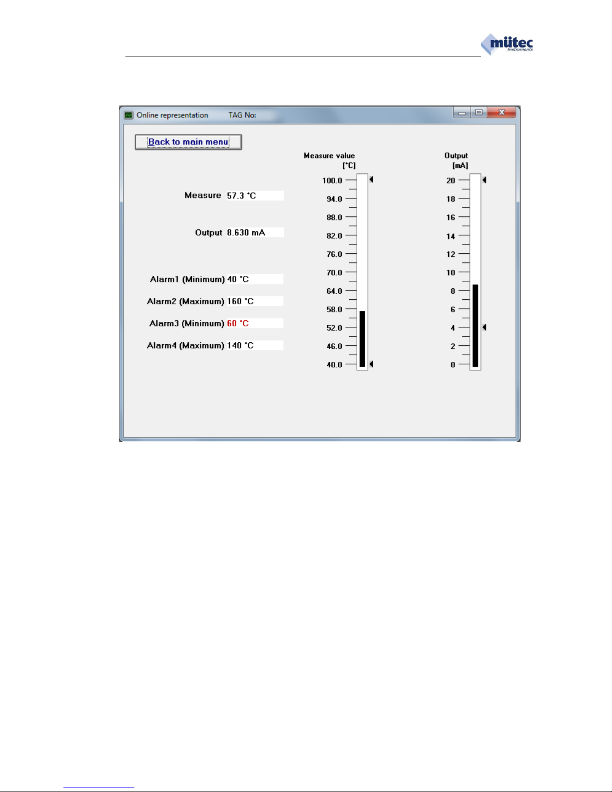
02/2014
_____________________________________________________________________________________________________________________
41
6.10. Online representation
The online representation shows the input and output signal both analogue and digital. Additional the alarms
with their limit values are figured. During exceeded limit value or alarm activation, the value is displayed in red.
Unused alarms (no function) are not recorded in the online display.
 Loading...