

Page 1
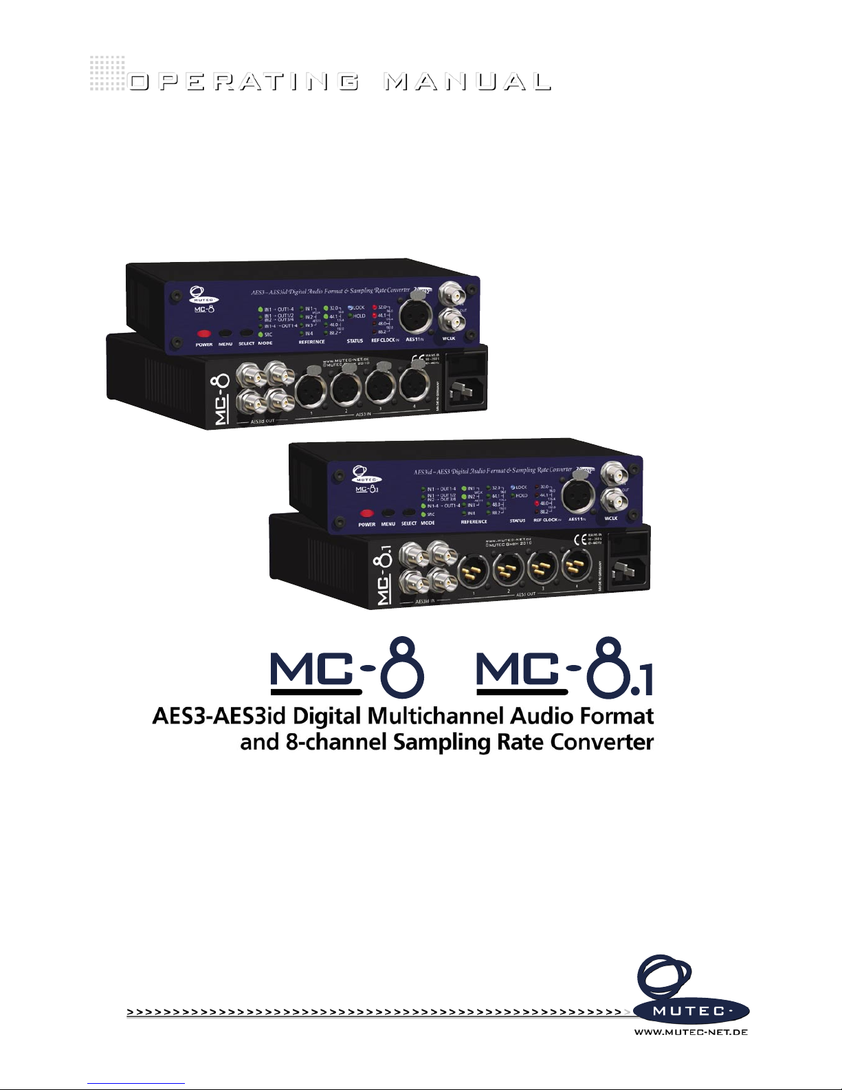
AES3-AES3id Digital Multichannel Audio Format
and 8-channel Sampling Rate Converter
+
Page 2

Page 3
MUTEC GmbH assumes no liability for any incorrect information given in this manual. Please note that
all software/hardware product names are registered trademarks of their respective owners. No part of
this manual may be reproduced, copied or converted to a machine-readable form or electronical media
without a written permission of MUTEC GmbH. We reserve the right to change or improve our products
without prior notice.
©
MUT EC GmbH 2 010
WARRANTY REGULATIONS
§1 Warranty
MUTEC GmbH warrants the flawless performance of this product to the original buyer for a period of two (2) years from the date of purchase. If any failure occurs within
the specified warranty period that is caused by defects in material and/or workmanship, MUTEC GmbH shall either repair or replace the product free of charge within 90
days. The purchaser is not entitled to claim an inspection of the device free of charge during the warranty period. If the warranty claim proves to be justified, the product
will be returned freight prepaid by MUTEC GmbH within Germany. Outside Germany, the product will be returned with the additional international freight charges payable
by the customer. Warranty claims other than those indicated above are expressly excluded.
§2 Warranty tra nsferability
This warranty is extended exclusively to the original buyer who bought the product from a MUTEC GmbH specialized dealer or distributor, and is not transferable to anyone
who may subsequently purchase this product. No other person (retail dealer, distributor, etc.) shall be entitled to give any warranty promise on behalf of MUTEC GmbH.
§3 Waranty reg ulations
The return of the completed registration card, or online registration on one of the websites specified below, is a condition of warranty. Failing to register the device before
returning it for repair will void the extended warranty.
The serial number on the returned device must match the one stated on the registration card or entered during online registration. Otherwise, the device will be
returned to the sender at the sender’s expense.
Any returned device must be accompanied by a detailed error description and a copy of the original sales receipt issued by a MUTEC dealer or distributor.
The device must be returned free of shipping expenses and in the original package, if possible; otherwise, the sender has to provide comparably protective packaging.
The sender is fully responsible for any damage or loss of the product when shipping it to MUTEC GmbH.
§4 Limitation of warranty
Damage s caused by t he followin g condition s are not cover ed by this warra nty:
Damage s caused by e very kind of normal wear an d tear (e.g. di splays, L EDs, pote ntiometers, fader s, switch es, buttons, conne cting ele ments, pr inted labe ls, cover
glass es, cover p rints, and s imilar par ts).
Funct ional failur e of the produc t caused by imp roper ins tallation ( please ob serve CM OS componen ts handling instruc tions!) , neglect o r misuse of
the pro duct, e.g . failure to operate the unit i n complianc e with the ins tructio ns given in the u ser or ser vice manual s.
Damage c aused by any f orm of exte rnal mechan ical impac t or modification.
Damage c aused by th e user’s fail ure to connec t and operate th e unit in compl iance with lo cal safet y regulatio ns.
Damage c aused by fo rce majeure (f ire, explo sion, flood, lightning, war, vandali sm, etc. ).
Conse quential da mages or def ects in pr oducts f rom other man ufacture rs as well as any costs res ulting from a l oss of produ ction.
Repair s carried out by perso nnel which is n ot authorize d from MUTEC G mbH will void t he warranty.
Adaptations and modifications to the device made with regard to
national, technical, or safety regulations in a country or of the customer do not constitute a warranty claim and should be set with MUTEC GmbH in advance.
§5 Repairs
To obtain warranty service, the buyer must call or write to MUTEC GmbH before returning the unit. All inquiries must be accompanied by a description of the problem and
the original buyer’s invoice. Devices shipped to MUTEC GmbH for repair without prior notice will be returned to the sender at the sender’s expense.
In case of a functional
failure please contact:
MUTEC G esellsc haft fuer Sys tementw icklung und Komponente nvertrieb mbH
Siekewe g 6/8 • 1230 9 Berlin • Ger many • Fon 030 -7468 80-0 • Fax 030-746 880- 99 • Tecsuppo [email protected] • www.MUTEC-net.de
JET and Jitter Elimination Technology are trademarks of TC Applied Technologies Ltd. The JET technology is used under sublicense from TC Applied Technologies Ltd., and is the intellectual property of
Sonopsis Ltd. Applicable patents include WO2004088845.
SAFETY INSTRUCTIONS
General inst ructions
To reduce the risk of fire or electrical shock, do not expose this appliance to rain or moisture, direct
sunlight or excessive heat from sources such as radiators or spotlights. No user serviceable parts are inside. Repair and maintenance must be carried out by qualified personnel authorized by MUTEC GmbH!
The unit has been designed for operation in a standard domestic environment. Do NOT expose the unit
and its accessories to rain, moisture, direct sunlight or excessive heat produced by such heat sources as
radiators or spotlights! The free flow of air inside and around the unit must always be ensured.
Initi al operatio n
Prior to t he initial op eration of th e unit, the ap pliance, it s accesso ries and pac kaging mus t be
inspe cted for an y signs of physical damag e that may have oc curred duri ng transit . If the unit ha s
been da maged mech anically or i f liquids hav e been spilled inside the e nclosure , the applian ce may
not be co nnected to t he mains or mu st be disco nnected f rom the mains i mmediately! If the unit i s
damag ed, please d o NOT return i t to MUTEC Gmb H, but notif y your dealer and t he shipping c om
-
pany immediately, o therwis e claims for damage or repl acement may n ot be grante d.
If the device is left in a low-temperature environment for a long time and then is moved to a roomtemperature environment, condensation may occur on the inside and the exterior. To avoid shortcircuits and flashovers, be sure to wait one or two hours before putting the device into operation.
Power su pply
The device contains a self-adapting wide-range power supply supporting the majority of global standard line voltages within a range of 90…250 V, with no need for making adjustments. Make sure that
your line-voltage source provides a supply voltage within the specified range. In addition, make sure
that the device is properly grounded via the local electric installation.
Pleas e use the encl osed power cord (see pa ckaging) to c onnect th e unit to the main s. Switch th e
unit of f before you a ttempt to co nnect it to t he mains. Co nnect the p ower cord to the unit, then
to a standard 3-pi n mains outlet. To draw the po wer cord, nev er pull on the ca ble but on the mains
plug!
The uni t must be grou nded during o peration !
For information on the power-inlet wiring, refer to the »Wirin g of connect ors« section in the
appendix. Disconnect the device from the mains when not using it for an extended period!
This symbol, an exclamation mark inside a triangle,
alerts you to important operating or safety instructions
in this manual.
This symbol, a flash of lightning inside a triangle, alerts
you to the presence of uninsulated dangerous voltage
inside the enclosure - voltage that may be sufficient to
constitute a risk of shock.
Decla ration of Con formity
We herewith confirm that the product complies with the European
Commission’s standards on electromagnetic compatibility.
Interference emission: EN 50081-1, 1992
Resistance to interference: EN 50082-1, 1992
Presupposed as operation condition is that all clock outputs are con
-
nected with high-quality and good shielded BNC 75 ohms cable.
!
R I S K O F
ELECTRICAL SHOCK!
C A U T I O N
!
Page 4

Page 5

CONTENT
INTRODUCTION
Main Differences between MC-8 and MC-8.1 . . . . . . . . . 7
General Function Description . . . . . . . . . . . . . . . . . 7
MC-8 + MC-8.1 Features . . . . . . . . . . . . . . . . . . . . 7
MC-8 + MC-8.1 Applications . . . . . . . . . . . . . . . . . . 7
Peripheral MUTEC Products
. . . . . . . . . . . . . . . . . . 8
CONTROL ELEMENTS AND TERMINALS
MC-8 + MC-8.1 Front Panel (both panels are equal) . . . . . . . 9
MC-8 Rear Panel . . . . . . . . . . . . . . . . . . . . . . . . 10
MC-8.1 Rear Panel . . . . . . . . . . . . . . . . . . . . . . . 10
INSTALLATION
Content of the Box . . . . . . . . . . . . . . . . . . . . . . . 11
Placing the device . . . . . . . . . . . . . . . . . . . . . . . 11
Wiring the Word Clock Interfaces
. . . . . . . . . . . . . . . 11
Wiring the AES/EBU and AES/EBUid Interfaces . . . . . . . . 12
GENERAL OPERATION
Selecting Function Menus and setting Functions . . . . . . 13
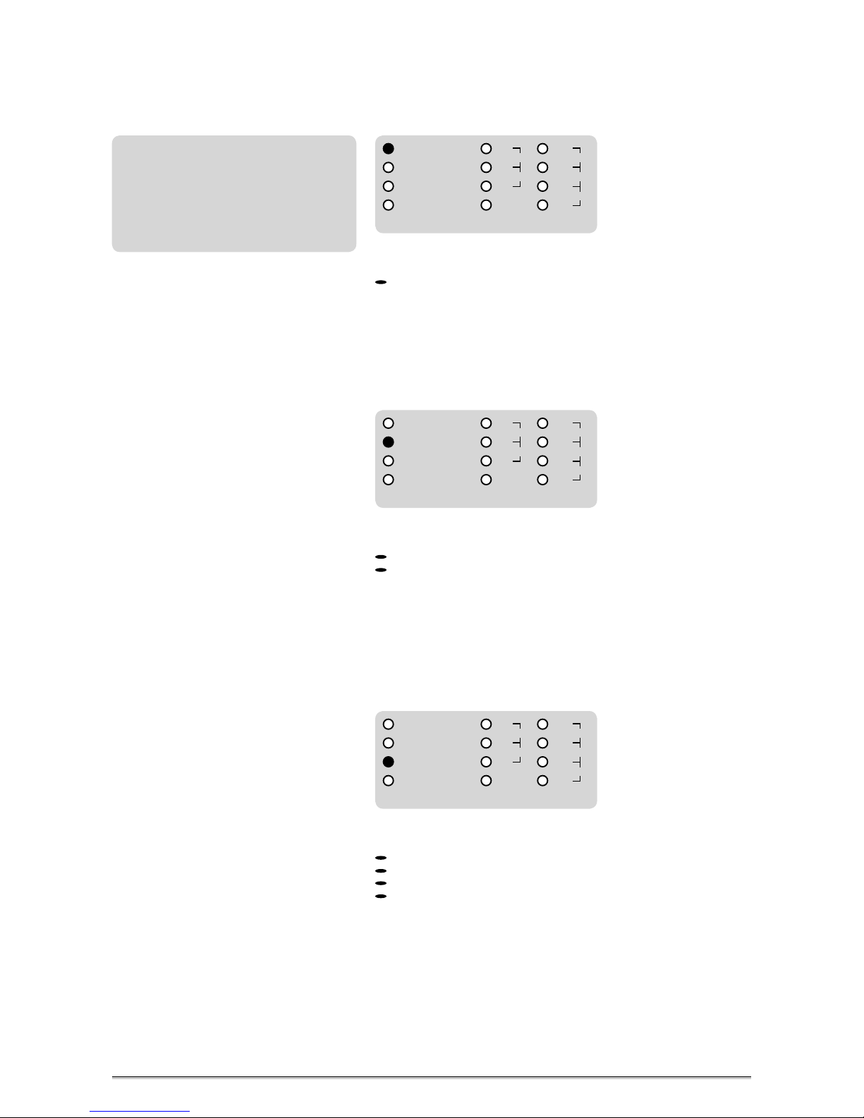
Steps of Operation . . . . . . . . . . . . . . . . . . . . . . . 13
OPERATING THE MC-8 + MC-8.1
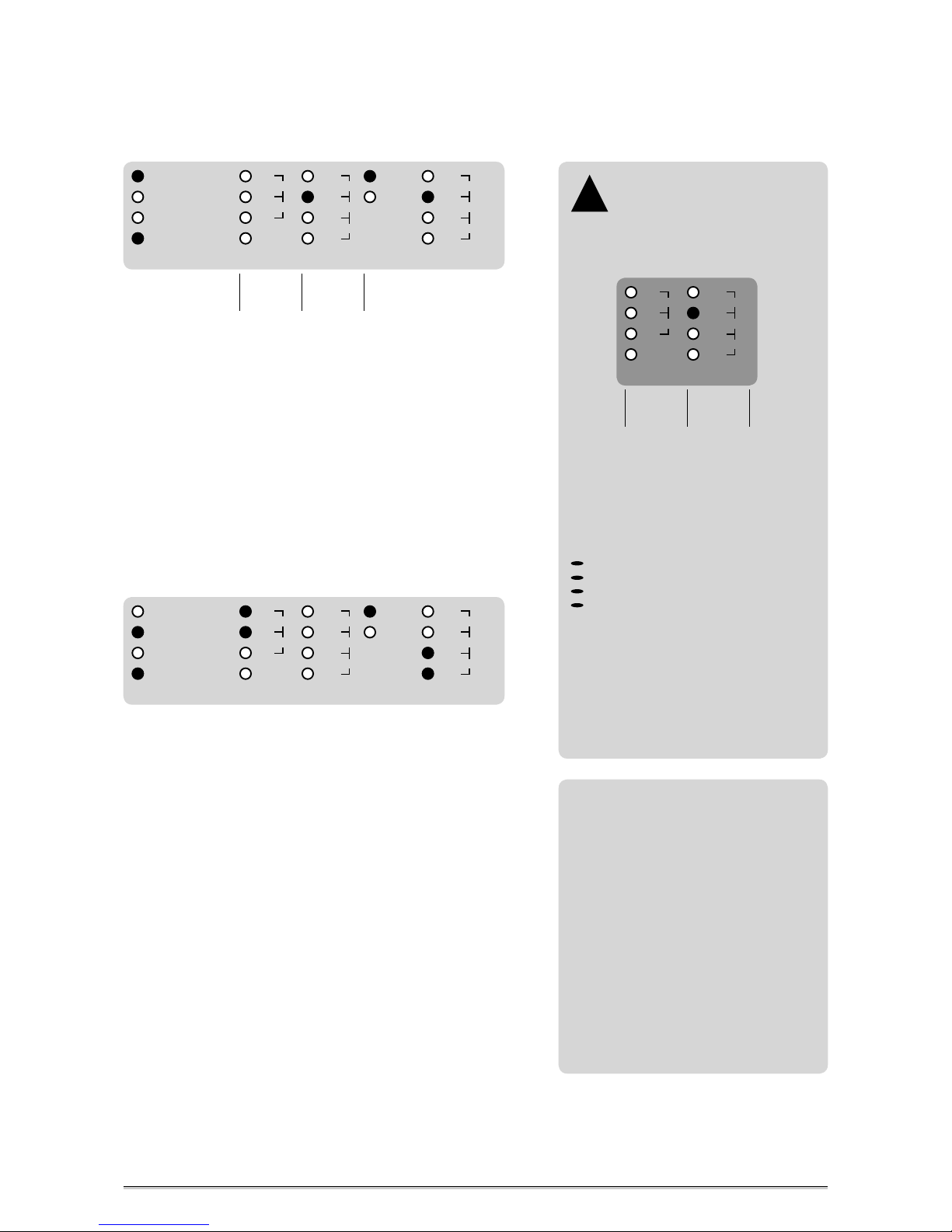
MODE and REFERENCE Menus . . . . . . . . . . . . . . . . . 15
General Operation Procedure
. . . . . . . . . . . . . . . . . 15
Conversion from one Input to all four Outputs
. . . . . . . 16
Conversion from two Inputs to two Output pairs
. . . . . . 16
Conversion from four Inputs to four Outputs . . . . . . . . 16
Conversion from one Input to all four Outputs
including the Sampling Rate Conversion Function . . . . . . 17
Conversion from two Inputs to two Output pairs
including the Sampling Rate Conversion Function . . . . . . 17
Conversion from four Inputs to four Outputs
including the Sampling Rate Conversion Function . . . . . . 18
STATUS Menu
. . . . . . . . . . . . . . . . . . . . . . . . . 18
REF CLOCK IN Menu . . . . . . . . . . . . . . . . . . . . . . . 18
APPENDIX
Pin Assignment of the Connectors . . . . . . . . . . . . . . 19
Switching-off the Termination of the Word Clock Input . . .
20
Technical Data . . . . . . . . . . . . . . . . . . . . . . . . . 21
Page 6

Page 7
> > > > > > > > > > > > > > > > > > > > > > > > > > > > > > > > > > > > > > > > > > > > > > > > > > > > > > > > > > > > > > > > > > > >
88
\
B E D I E N E L E M E N T E
B E D I E N E L E M E N T E
B E D I E N E L E M E N T E
> > > > > > > > > > > > > > > > > > > > > > > > > > > > > > > > > > > > > > > > > > > > > > > > > > > > > > > > > > > > > > > > > > > >
INTRODUCTION
Thank you very much for purchasing the MC-8 or MC-8.1, AES3-AES3id Digi-
tal Multichannel Audio + 8-channel Sampling Rate Converter, from MUTEC!
Main Differences between MC-8 and MC-8.1
This manual refers to both devices, the MC-8 and the MC-8.1, because of
their nearly identical functionalities. Both are unidirectional converters. The
main difference are their conversion directions:
The MC-8 converts from AES3 to AES3id
The MC-8.1 converts from AES3id to AES3
The whole remaining functionalities are totally identical!
General Function Description
The MUTEC MC-8 and MC-8.1 are extremely flexible, high-performance
8 channel AES3-AES3id digital audio and sampling rate converters.
The MC-8 converts and distributes unidirectionally AES3 to AES3id signals,
whereas the MC-8.1 works in the opposite conversion direction. Both
devices process digital audio signals up to 192.0kHz in all operation modes.
Based on latest FPGA designs, the MC-8 and MC-8.1 achieve levels of
performance regarding their signal qualities, unique flexibilities, clocking
features and their 8 channel sampling rate conversion engines (SRC), which
are outstanding in today’s industry!
Various operation modes enable the use of the MC-8 and MC-8.1 in many
applications. Apart from the standard function to convert four individual
AES3 or AES3id stereo signals into the appropriate other format, the devices can also work as a signal splitters and distributors.
All conversions can be carried out with or without SRC functionality. The
SRC engine is synchronizable to Word Clock, AES11, any digital audio input
and the internal, ultra low-jitter clock base in every operation mode. When
using the MC-8 or MC-8.1 with their SRCs locked to an external reference,
the built-in HOLD function secures interruption-free audio conversion even
in cases of an unstable or absent clock reference!
This all makes MC-8 and MC-8.1 for sure the most flexible and useful AES3
to AES3id digital audio converters allowing to handle any conversion application with ease.
MC-8 + MC-8.1 Features
Converts AES3 to AES3id (MC-8), or vice versa (MC-8.1), on 8 channels
Works also as signal splitter or distributor
Extracts and re-generates clock signals out of digital audio signals
Improves audio quality of connected devices
Accepts all Word Clock and AES11 clock references from
32.0kHz to 192.0kHz
Protects from reference signal dropouts and losses
Supplies interruption-free audio output signals in SRC mode
AES11, Grade 1, internal reference clock (<1ppm)
Easy to configure
Compact case size fits in every studio set-up
Built-in international power supply
MC-8 + MC-8.1 Applications
AES3 to AES3id, or vice versa, audio and sampling rate conversions
Conversions and signal splittings simultaneously
Audiophil clock recovery and signal regeneration
Interconnection of symmetrically and unsymmetrically AES/EBU
environments
Line extension for e.g. theatre or broadcast installations
Usable within small studio set-ups up to broadcast installations
7
Boxes which contain a triangle with
an exclamation mark inside should
be read carefully! These include
additional information which are of major
importance for the functional descriptions
in the text column.
!
The grey boxes contain supplementary
informationen for the corresponding
sections in the text columns. The content of
the individual box refers to the description
in the text column beside the box.
Page 8

\\\\\\\\\\\\
I N T R O D U C T I O N
I N T R O D U C T I O N
I N T R O D U C T I O N
> > > > > > > > > > > > > > > > > > > > > > > > > > > > > > > > > > > > > > > > > > > > > > > > > > > > > > > > > > > > > > > > > > > >
> > > > > > > > > > > > > > > > > > > > > > > > > > > > > > > > > > > > > > > > > > > > > > > > > > > > > > > > > > > > > > > > > > > >
88
8
Peripheral MUTEC Products
Reference Clocks and Master Clocks for Synchronization:
iCLOCK + iCLOCKdp
iCLOCK and iCLOCKdp are synchronizable, high-precision clock
generators which are designed to be the reference in digital audio and
video studios as well as broadcast and television stations. For further
details please visit:
MC-3
The MC-3 SMART CLOCK is an universal digital audio master clock
generator. The unit provides different high-stable and Ultra low-jitter
clock signals for synchronization of various digital audio devices.
MC-3.1
The MC-3.1 SMART CLOCK SD is an universal digital audio and SD video
sync master clock generator. The unit provides different high-stable
clock signals for simultaneous synchronization of digital audio and SD
video devices.
MC-3.2
The MC-3.2 SMART CLOCK HD is an universal digital audio and SD/HD
video sync master clock generator. The unit provides different highstable clock signals for simultaneous synchronization of digital audio
and SD/HD video devices.
Signal Distribution Amplifier
MC-2
The MC-2 is a high-performance digital audio and reference sync
signal distribution amplifier for AES3/11 and AES3/11id signals. The
unit distribute s and converts between the mentioned AES signals and
standards.
Format and Sampling Rate Converters with internal Master Clock:
MC-4
The MC-4 is a high-performance digital audio multichannel format and
sampling rate converter for ADATTM, AES3 and S/P-DIF
MC-6
The MC-6 is a high-performance digital audio dual channel format converter for AES3, AES3id and S/P-DIF.
For all peripheral products please have a look on our website:
www.MUTEC-NET.de !
Page 9
> > > > > > > > > > > > > > > > > > > > > > > > > > > > > > > > > > > > > > > > > > > > > > > > > > > > > > > > > > > > > > > > > > > >
88
\
B E D I E N E L E M E N T E
B E D I E N E L E M E N T E
B E D I E N E L E M E N T E
> > > > > > > > > > > > > > > > > > > > > > > > > > > > > > > > > > > > > > > > > > > > > > > > > > > > > > > > > > > > > > > > > > > >
CONTROL ELEMENTS AND TERMINALS
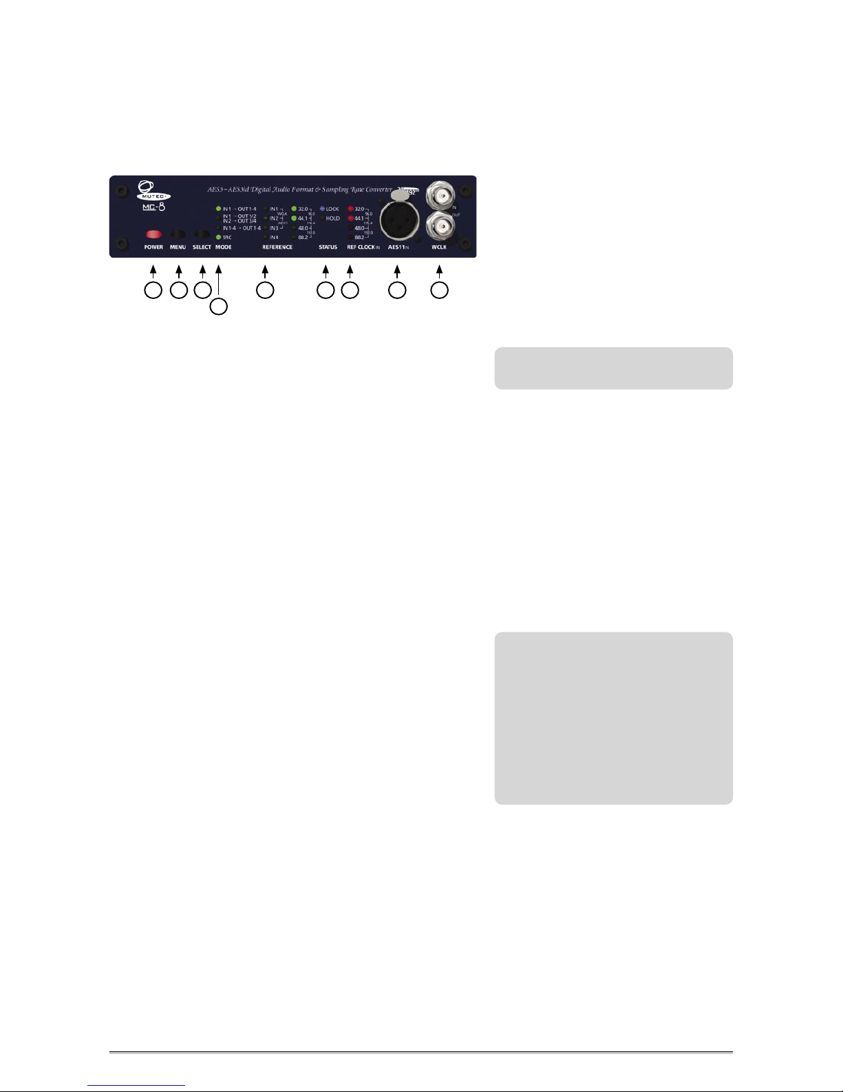
MC-8 + MC-8.1 Front Panel (both panels are equal)
1 POWER
This red LED lights up when the unit is switched on with the rear panel
POWER switch.
2 MENU
This key selects one of the available function menus.
3 SELECT
Use this key to select a function within a specific function menu.
4 MODE
This menu allows to select all conversion and splitting functions with or
without SRC functionality in a logical manner.
5 REFERENCE
This function menu allows to select the master clock reference for synchronization of the SRCs.
6 STATUS
This menu indicates various signal statuses of the incoming clock reference
for the SRCs.
7 REF CLOCK IN
This menu indicates the clock rate of the selected reference clock signal.
8 AES11 IN
This input receives a balanced digital AES11 blank frame signal in compliance with AES11–1997/2003 as master clock reference for the SRCs.
Alternatively, an AES3 digital audio signal in compliance with AES3 –1992
(R1997) or a S/PDIF digital audio signal aligned to IEC60958 can be input as
well. The input impedance is 110 Ω (XLR connector, female).
9 WCLK IN + OUT
The above BNC connector (IN) receives a Word Clock or so-called »Super Clock« signal as master clock reference for the SRCs. The below BNC
connector (OUT) transmits an low-jitter Word Clock signal based on the
internal clock basis or the selected external clock reference signal. The impedances of both connectors are 75 Ω (BNC connectors, female).
9
Refer to the OPERATIONS chapter for more
information.
Differences between AES3 and AES11
Both standards, published by the Audio
Engineering Society (AES), are based on the
same interface, commonly called as AES/EBU
interface which uses XLR connectors.
The AES3 standard carries both, the digital
audio data and the reference clock information. The AES11, also known as ‚blank frame
signal‘, does not carry any digital audio
data, but only the reference clock information for synchronization.
4
3
2
1
6
7
8
9
5
Page 10
\\\\\\\\\\\\\
C O N T R O L E L E M E N T S
C O N T R O L E L E M E N T S
C O N T R O L E L E M E N T S
> > > > > > > > > > > > > > > > > > > > > > > > > > > > > > > > > > > > > > > > > > > > > > > > > > > > > > > > > > > > > > > > > > > >
> > > > > > > > > > > > > > > > > > > > > > > > > > > > > > > > > > > > > > > > > > > > > > > > > > > > > > > > > > > > > > > > > > > >
88
10
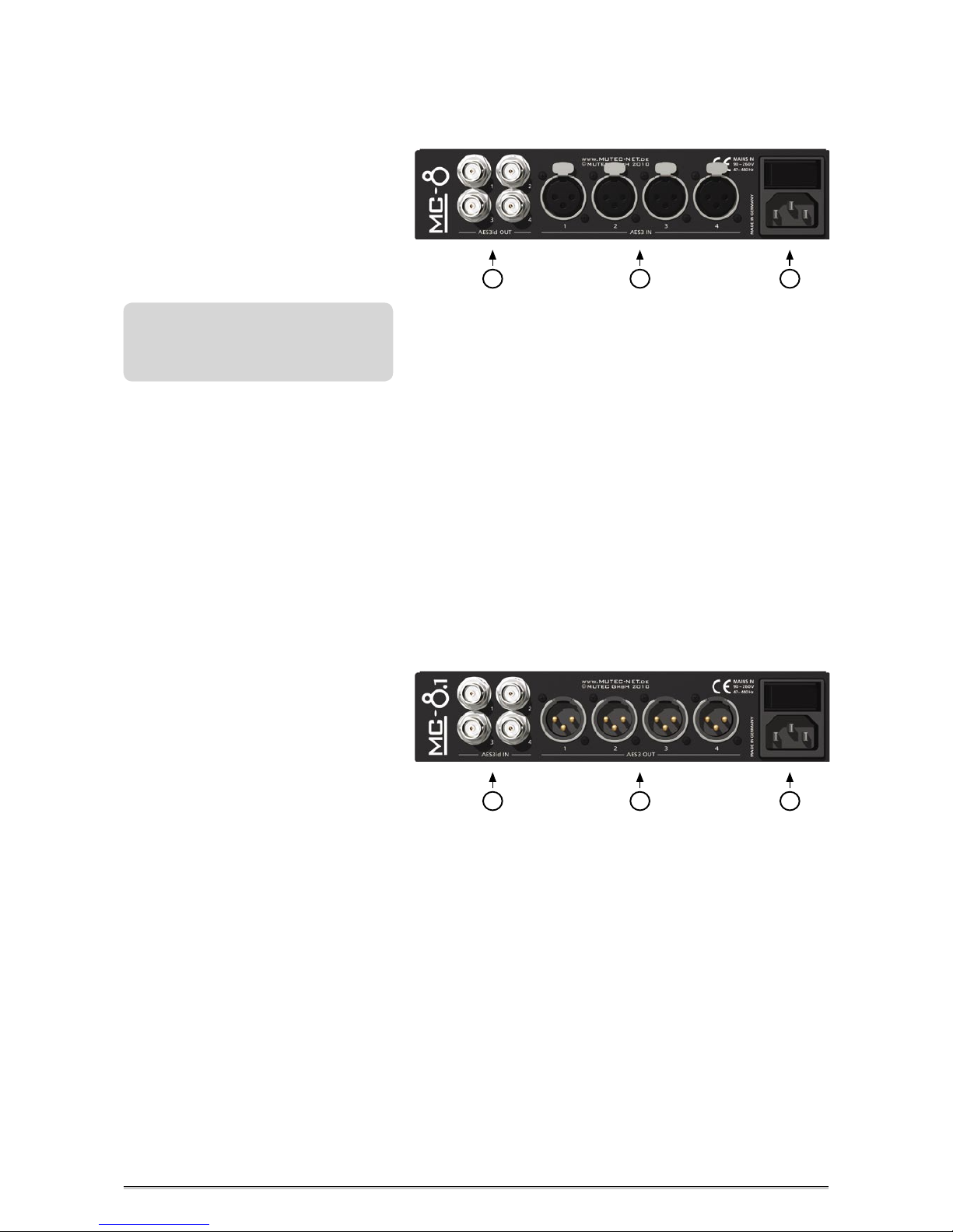
1 AES3id OUT 1– 4
These four AES/EBUid output interfaces transfer AES3id digital audio stereo
signals in compliance with the AES3id–2001 standard. Their numbering is
aligned to this one of the four AES/EBU inputs. The output impedances of
the connectors are 75 Ω (BNC connectors, female).
2 AES3 IN
These four AES/EBU input interfaces can receive a balanced digital AES3 or
AES11 signal in compliance with AES3 –1992 (R1997) or AES11–1997/2003.
Their numbering is aligned to this one of the four AES/EBUid outputs. The
input impedance is 110 Ω (XLR connector, female).
3 MAINS IN, Power Switch + Power Inlet
This is the main switch for switching the device on and off. Be sure to
make all connections (especially the supplied power cable) properly before
turning on the switch. Heed the SAFETY INSTRUCTIONS at the beginning of
this manual.
Connect the supplied power cable here. Make sure that the power switch
is turned off before connecting the power cable to this inlet and to the
power outlet. Line voltages within the range of 90…260V with a frequencies between 47...440Hz can be applied. The internal power supply will
automatically make all necessary adjustments.
MC-8 Rear Panel
For detailed specifications on all terminals,
refer to the »Pin Assignment of the
Connectors« and »Technical Data« in the
chapter »APPENDIX«.
1 AES3id IN 1– 4
These four AES/EBUid input interfaces receive AES3id digital audio stereo
signals in compliance with the AES3id–2001 standard. Their numbering is
aligned to this one of the four AES/EBU outputs. The input impedances of
the connectors are 75 Ω (BNC connectors, female).
2 AES3 OUT
These four AES/EBU output interfaces transmit a balanced digital AES3 or
AES11 signal in compliance with AES3 –1992 (R1997) or AES11–1997/2003.
Their numbering is aligned to this one of the four AES/EBUid inputs. The
output impedance is 110 Ω (XLR connector, female).
3 MAINS IN, Power Switch + Power Inlet
This is the main switch for switching the device on and off. Be sure to
make all connections (especially the supplied power cable) properly before
turning on the switch. Heed the SAFETY INSTRUCTIONS at the beginning of
this manual.
Connect the supplied power cable here. Make sure that the power switch
is turned off before connecting the power cable to this inlet and to the
power outlet. Line voltages within the range of 90…260V with a frequencies between 47...440Hz can be applied. The internal power supply will
automatically make all necessary adjustments.
MC-8.1 Rear Panel
1
2
3
1
2
3
Page 11
> > > > > > > > > > > > > > > > > > > > > > > > > > > > > > > > > > > > > > > > > > > > > > > > > > > > > > > > > > > > > > > > > > > >
88
\
B E D I E N E L E M E N T E
B E D I E N E L E M E N T E
B E D I E N E L E M E N T E
> > > > > > > > > > > > > > > > > > > > > > > > > > > > > > > > > > > > > > > > > > > > > > > > > > > > > > > > > > > > > > > > > > > >
11
INSTALLATION
Content of the Box
The unit was packed carefully. Nevertheless we recommend to check the
content directly after opening the package:
1 x MC-8 or MC-8.1
1 x Power cable
4 x Rubber feet
1 x Manual
Placing the Device
The unit should be set up as closely as possible to the devices to which it
will be connected, so as to avoid excessive cable lengths. Use the 4 rubber
feets enclosed with the appliance and stick them symmetrically on the
bottom side of the unit to protect the enclosure and supporting surface
from being damaged.
The device can be mounted into a standard 19“ rack and will require 1
unit, using the MW-05/19 rack mounting kit (MUTEC item no. 8020-035). In
this case, the rubber feet cannot be attached. Please make sure that there
is enough space on the right and left hand side of the device to enable
sufficient air convection! The mounting depth including the terminals is
160 mm/6.7“. Another 60 mm/2.4“ should be added for the required cables.
Wiring the Word Clock Interfaces
To allow for the synchronization of signals, the interfaces of all devices
involved must be properly connected to each other, so as to ensure a logical
signal flow. Always be sure to connect the Word Clock output of the MC-8
or MC-8.1 to the corresponding input of the device you wish to synchronize. Cable lengths should be kept as short as possible to minimize signal
losses and/or interferences!
For the transmission of Word Clock signals electrical, unsymmetrical cables
with a resistance of 75 Ω and BNC connectors on both ends are used. Typi-
cally, such cables are marked »RG-59U, R G59B/U«.
Additionally, you should make sure that the Word Clock input to be con
nected to the MC-8’s or MC-8.1’s output has a 75 Ω terminating resistor!
Most Word Clock inputs allow for enabling/disabling the termination with
a so-called »termination-switch«, which may be located on the outside or
inside of the device.
For devices which have no termination of the Word Clock input, e.g. RME
Hammerfall with Word Clock i/o, Alesis BRC or M-Audio ProFire Lightbridge, you can use an additional BNC-T piece to terminate the input. Plug
the T piece with its center connector into the input of the receiving device.
Then, connect the cable coming from the MC-8’s or MC-8.1’s Word Clock
output to one of the lateral connectors, and the other connector of the
BNC-T piece to a 75 Ω resistor forming the BNC termination.
Basically, you should avoid »looping through« Word Clock leads by means
of passive BNC-T pieces to preserve the signal quality, as level drops will be
the result. If there is no other way to wire your set-up, please make sure
that all Word Clock inputs (except for the last device in the chain) have
their terminations disabled! In a serial Word Clock chain only the last clock
input should have a termination! Never connect more than three devices in
series to one output!
Before installing the unit the section
SAFETY INSTRUCTIONS located
at the beginning of this manual
should be read carefully.
!
The condition of the packaging material
and the device should be checked carefully
additionally. If there are any damages please
refer to SAFETY INSTRUCTIONS, Initial
Operation, and WARRANTY REGULATIONS.
Never expose the device and
accessories to rain, moisture,
direct sunlight, or excessive heat
produced by radiators, heaters, or spot
lights! Sufficient air circulation in the
environment of the device must be ensured!
!
It is imperative that the lengths
of all cables connected are largely
the same, as this is the only way to
ensure that all devices will be synchronized
in phase (exception: cable tolerances).
Please make sure that the cable used has a
resistance of 75
Ω, in compliance with the
specifications! If a cable with a different
resistance is used, a dramatic deterioration
of the signal quality can be the result! In
this case, the perfect synchronization of all
devices involved could be impaired.
We recommend using high-grade cables with
a good shielding. A length of max. 10 meters
(approx. 30 feets) should not be exceeded!
!
Register your Product for
Warranty and Support!
We ask you to be so kind to register
your product through our website immedi
ately after purchasing. This ensures full warranty services over a period of two years
after purchasing the product. More-over,
for all registered products we offer to our
customers technical support. Additionally
we will inform you about product updates
and new products which may of interest for
you (on voluntary base, of course).
Please regsiter your product at:
www.MUTEC-net.de
!
Page 12

\\\\\\\\\\\\
I N S TALLAT I O N
I N S TALLAT I O N
I N S TALLAT I O N
> > > > > > > > > > > > > > > > > > > > > > > > > > > > > > > > > > > > > > > > > > > > > > > > > > > > > > > > > > > > > > > > > > > >
> > > > > > > > > > > > > > > > > > > > > > > > > > > > > > > > > > > > > > > > > > > > > > > > > > > > > > > > > > > > > > > > > > > >
88
12
Wiring the AES/EBU and AES/EBUid Interfaces
AES/EBU
Connect the AES/ EBU interfaces with the help of balanced electrical
cables equipped with XLR connectors on both ends. The specifications
stipulate a specific cable resistance of 110
Ω (ask your retailer for a confir-
mation of this value when purchasing the cables).
AES/EBUid
Connect the AES/ EBUid interfaces with the help of unbalanced electrical
BNC cables equipped with BNC connectors on both ends (same as used for
Word Clock). The specifications stipulate a specific cable resistance of 75
Ω
(ask your retailer for a confirmation of this value when purchasing the
cables).
Typically, such cables are marked »RG-59U, RG59B/U«.
Especially when working with high
AES/EBU clock rates well shielded
clock lines are imperative to avoid
increased radiation! Standard cables are normally useable for clock rates up to 50.0kHz.
Special shielded cable material should be
used for transfer of higher clock rates.
!
Since some manufacturers offer optimized
cables for the transmission of digital AES/
EBU and AES/EBUid audio signals, it will be
a good idea to ask your retailer for specific
cables.
Page 13
> > > > > > > > > > > > > > > > > > > > > > > > > > > > > > > > > > > > > > > > > > > > > > > > > > > > > > > > > > > > > > > > > > > >
88
\
B E D I E N E L E M E N T E
B E D I E N E L E M E N T E
B E D I E N E L E M E N T E
> > > > > > > > > > > > > > > > > > > > > > > > > > > > > > > > > > > > > > > > > > > > > > > > > > > > > > > > > > > > > > > > > > > >
13
GENERAL OPERATION
Selecting Function Menus and setting Functions
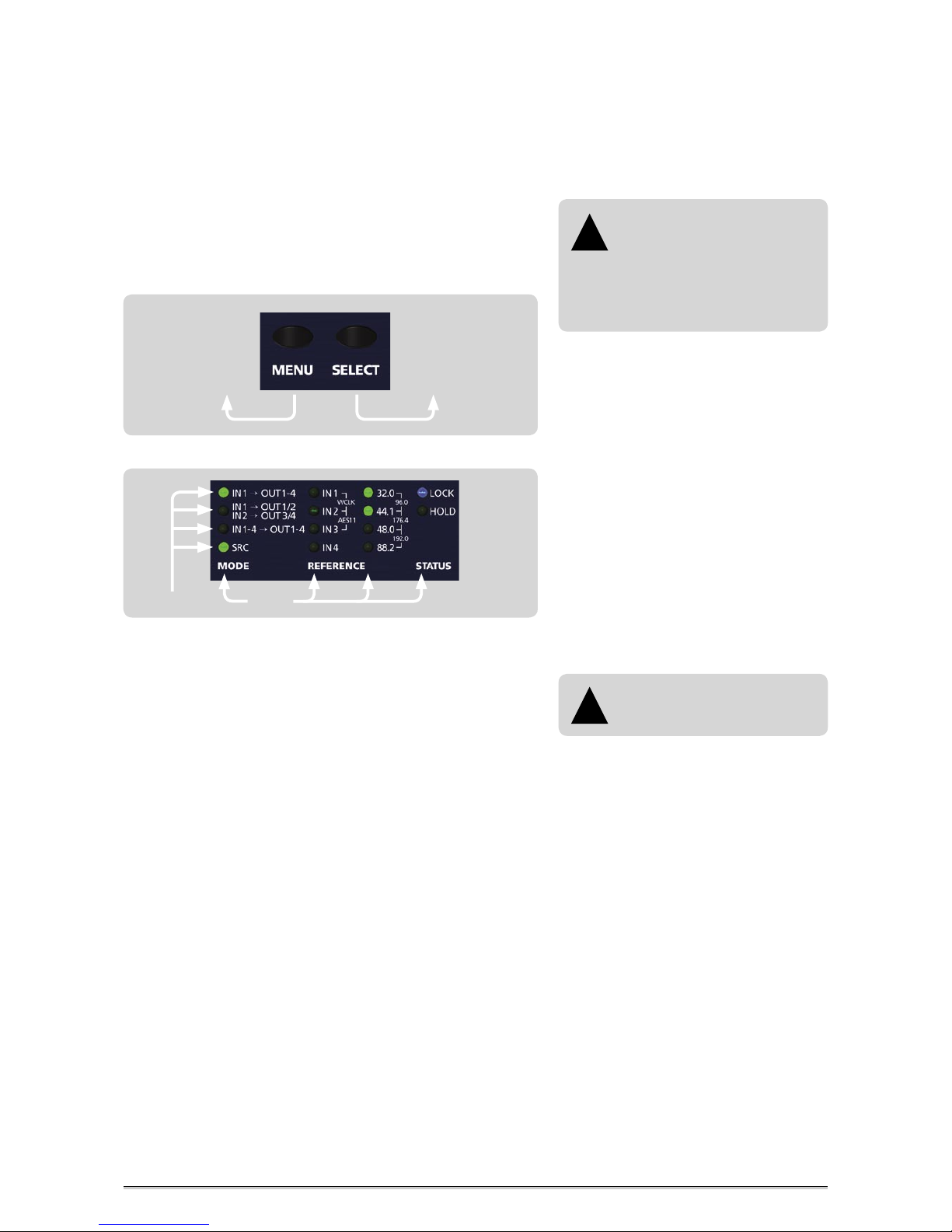
The device is fully operated using the two toggle switches at the front
panel.
1 Switching the »MENU« key toggles between different basic function menus.
2 Switching the »SELECT« key activtes individual functions within one
function menu.
Steps of Operation
1 First press on »MENU« or »SELECT« key enables the last selected function
within the last selected function menu. The corresponding LED is
beginning to flash.
2 Every press on »SELECT« key will select a new function within a menu. The
LED of every selected function will flash accordingly and the
corresponding function is vailable at once.
3 When the needed function is selected, do not press the switches again!
After a period of approx. 4 seconds the LED in front of the selected
function will stop flashing.
The »STATUS« area is not accessible by using the »MENU« and »SELECT«
switches, because it only informs about different conditions of incoming
signals.
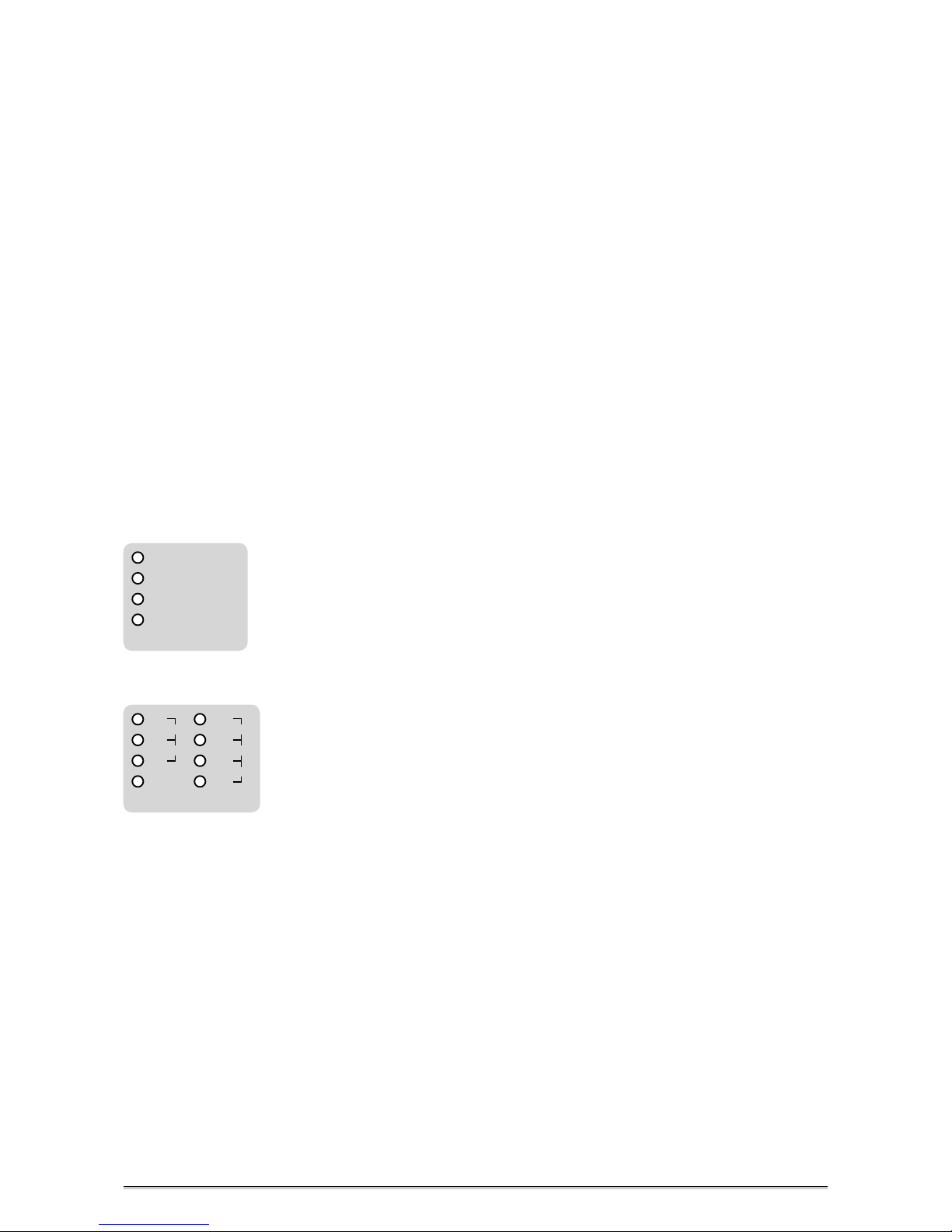
Function Areas + Functions
MenusFunctions
For safety reasons, be sure to read
the SAFETY INSTRUCTIONS and
INSTALLATION chapters before first
powering-up!
We also recommend reading the chapter
CONTROL ELEMENTS AND TERMINALS for
information on how to connect your MC-8
or MC-8.1!
!
All user-specific function settings
are available furthermore when
power is restored.
!
2. SELECT
selects individual
functions within
one function area.
1. MENU
selects individual
function menus.
MENU + SELECT operation
Page 14

Page 15
> > > > > > > > > > > > > > > > > > > > > > > > > > > > > > > > > > > > > > > > > > > > > > > > > > > > > > > > > > > > > > > > > > > >
88
\
B E D I E N E L E M E N T E
B E D I E N E L E M E N T E
B E D I E N E L E M E N T E
> > > > > > > > > > > > > > > > > > > > > > > > > > > > > > > > > > > > > > > > > > > > > > > > > > > > > > > > > > > > > > > > > > > >
OPERATING THE MC-8 or MC-8.1
MODE and REFERENCE Menus
These both menus are offering access to the whole functionality of your
MC-8 or MC-8.1.
The »MODE« menu contains of one LED raw. With help of this menu you
can select every conversion function, with or without SRC functionality.
If the LED »SRC« is selected, you have access to the second menu which is
called »REFERENCE«. Otherwise, this second menu is not accessible.
The »REFERENCE« menu supplies all necessary synchronization options for
the different conversions functions and the use of the internal sampling
rate converters (SRC).
The menus »STATUS« and »REF CLOCK IN« are for control of the MC-8‘s or
MC-8.1‘s operation status only. They are not accessable for adjustments.
General Operation Procedure
The MC- and MC-8.1 menus are strictly organized aligned to generally usual
handling procedures when inserting such a box into your studio set-up. So,
you can split up all of the necessary adjustments in two simple steps, which
leads to the following two questions for the basic operation of your MC-8
or MC-8.1:
1) How I want to convert? With or without SRC function? → MODE
2) Using the SRCs, which clock reference do I need for them? → REFERENCE?
After these general decisions are made, your MC-8 or MC-8.1 is configured
for optimal operation in your set-up. Due to the fact that the system
monitors for useful function combinations, maloperation is not possible.
So, let‘s have a look to the individual functions on the next pages.
15
SRC = Activates the sampling rate converters
IN1 → OUT1/2
IN2 → OUT3/4
IN1 → OUT1- 4 = Input 1 to all 4 outputs
IN1- 4
→
OUT1- 4 = Inputs 1 to 4 converted to output 1 to 4
MODE
= Input 1 to Outputs 1 + 2, Input 2 to outputs 3 + 4
REFERENCE
88.2
48.0
44.1
32.0
192.0
96.0
176.4
IN3
IN2
IN1
IN4
WCLK
AES11
Page 16
\\\\\\\\\\\\
O P E R AT I O N
O P E R AT I O N
O P E R AT I O N
> > > > > > > > > > > > > > > > > > > > > > > > > > > > > > > > > > > > > > > > > > > > > > > > > > > > > > > > > > > > > > > > > > > >
> > > > > > > > > > > > > > > > > > > > > > > > > > > > > > > > > > > > > > > > > > > > > > > > > > > > > > > > > > > > > > > > > > > >
88
16
This setting enables to convert one input signal only (at input 1) to all four
outputs simultaneously. That means:
Input 1 → Outputs 1+ 2+3 + 4
Using this function, your MC-8 or MC-8.1 works as a typical 1→ 4 digital audio signal distribution amplifier. The input signal can be between 32.0kHz
and 192.0kHz. Because the SRC function is not selected, your MC-8 or
MC-8.1 is only electrically converting the signals and no adjustments in the
»REFERENCE« menu can be carried out.
Conversion from one Input to all four Outputs
REFERENCE
88.2
48.0
44.1
32.0
192.0
96.0
176.4
IN3
IN2
IN1
IN4
WCLK
AES11
IN1- 4 → OUT1- 4
IN1 → OUT1/2
IN2 → OUT3/4
IN1
→
OUT1- 4
SRC
MODE
This setting enables to convert two individual input signals (at inputs 1+ 2)
to two output pairs, one output pair for every input signal. That means:
Input 1 → Outputs 1+ 2
Input 2 → Outputs 3 + 4
Using this function, your MC-8 or MC-8.1 works as a typical digital audio
signal splitter for two independent signals. The signals can be based on
different sampling rates between 32.0kHz and 192.0kHz at the same time.
Because the SRC function is not selected, your MC-8 or MC-8.1 is only
electrically converting the signals and no adjustments in the »REFERENCE«
menu can be carried out.
Conversion from two Inputs to two Output pairs
REFERENCE
88.2
48.0
44.1
32.0
192.0
96.0
176.4
IN3
IN2
IN1
IN4
WCLK
AES11
IN1- 4 → OUT1- 4
IN1 → OUT1/2
IN2 → OUT3/4
IN1
→
OUT1- 4
SRC
MODE
This setting enables to convert four individual input signals to the four
outputs available. That means:
Input 1 → Output 1
Input 2 → Output 2
Input 3 → Output 3
Input 4 → Output 4
The signals can be based on different sampling rates between 32.0kHz and
192.0kHz at the same time. Because the SRC function is not selected, your
MC-8 or MC-8.1 is only electrically converting the signals and no adjustments in the »REFERENCE« menu can be carried out.
Conversion from four Inputs to four Outputs
REFERENCE
88.2
48.0
44.1
32.0
192.0
96.0
176.4
IN3
IN2
IN1
IN4
WCLK
AES11
IN1- 4 → OUT1- 4
IN1 → OUT1/2
IN2 → OUT3/4
IN1
→
OUT1- 4
SRC
MODE
Function of Word Clock output when signal
converting only
When you are using your MC-8 or MC-8.1 as
electrical signal converter between AES/EBU
and AES/EBUid only (as described on this
page here), the Word Clock output on the
rear will not carry a reference clock signal.
Page 17
\\\\\\\\\\\\
O P E R AT I O N
O P E R AT I O N
O P E R AT I O N
> > > > > > > > > > > > > > > > > > > > > > > > > > > > > > > > > > > > > > > > > > > > > > > > > > > > > > > > > > > > > > > > > > > >
> > > > > > > > > > > > > > > > > > > > > > > > > > > > > > > > > > > > > > > > > > > > > > > > > > > > > > > > > > > > > > > > > > > >
88
17
This setting enables to convert one input signal only (at input 1) to all four
outputs simultaneously, as described on page 16.
Now, the internal sampling rate converters (SRC) are activated additionally
and it is necessary to select a reference clock in the »REFERENCE« menu. In
the above displayed example, the internal clock generator is selected with
44.1kHz clock rate. That means, not depending on the clock rate of the
incoming signal, the outgoing signals will all carry the clock rate selected in
the »REFERENCE« menu.
In the »STATUS« menu the blue LED »LOCK« is lighting and shows that the
SRCs are locked to the internal clock generator.
In the »REF CLOCK
IN« menu, the red LED »44.1« is lighting and thus shows
the clock rate of the reference clock, that means the internal clock generator,
which is here 44.1kHz.
Conversion from one Input to all four Outputs including the
Sampling Rate Conversion Function
REFERENCE
88.2
48.0
44.1
32.0
192.0
96.0
176.4
IN3
IN2
IN1
IN4
WCLK
AES11
IN1- 4 → OUT1- 4
IN1 → OUT1/2
IN2 → OUT3/4
IN1
→
OUT1- 4
SRC
MODE
Internal
Clock
References
External
Clock
References
Conversion from two Inputs to two Output pairs including the
Sampling Rate Conversion Function
HOLD
LOCK
88.2
48.0
44.1
32.0
192.0
96.0
176.4
STATUS REF CLOCK IN
This setting enables to convert two individual input signals (at inputs 1+ 2)
to two output pairs, one output pair for every input signal, as described on
page 16.
In the above displayed example, Word Clock (WCLK) is selected as clock
reference for the internal SRCs.
In the »STATUS« menu the blue LED »LOCK« is lighting and shows that the
SRCs are locked to the externally supplied Word Clock signal.
In the »REF CLOCK IN« menu, the last two red LEDs in the row light in front
of »192.0« and thus show the clock rate of the externally supplied Word
Clock signal, which is 192.0kHz.
REFERENCE
88.2
48.0
44.1
32.0
192.0
96.0
176.4
IN3
IN2
IN1
IN4
WCLK
AES11
IN1- 4 → OUT1- 4
IN1 → OUT1/2
IN2 → OUT3/4
IN1
→
OUT1- 4
SRC
MODE
HOLD
LOCK
88.2
48.0
44.1
32.0
192.0
96.0
176.4
STATUS REF CLOCK IN
References for Sampling Rate
Conversion
Your MC-8 or MC-8.1 allows to synchronize the internal SRCs to various clock
reference signals. These possible references
can be selected in the »REFERENCE« menu:
!
REFERENCE
88.2
48.0
44.1
32.0
192.0
96.0
176.4
IN3
IN2
IN1
IN4
WCLK
AES11
Internal
Clock
References
External
Clock
References
Aligned to the clock reference type which
you want to supply, you must select the
corresponding clock reference within the
»REFERENCE« menu. Enter the »REFERENCE«
menu by pressing the »MENU« button and
press then the »SELECT« button repeatedly
to select the corresponding clock reference.
Selectable clock references are:
IN1-4 = Digital audio input no. 1, 2, 3 or 4
WCLK = Word Clock or Super Clock
AES11 = AES11 blank frame signal
32.0 -192.0 = Internal clock generator
When the external reference clock signal
can be locked by the internal PLL circuit, the
blue LED »LOCK« in the »STATUS« menu
will light constantly. The clock rate of the
selected clock source is then displayed in
the »REF CLOCK IN« menu. External clock
references can be supplied with all audiorelated clock frequencies between 32.0kHz
and 192.0kHz.
Function of Word Clock output when
activating the SRCs
When you are using the sampling rate
conversion function of your MC-8 or MC-8.1,
the selected reference clock will be output
through the Word Clock output at the rear
for synchronization of other devices.
If you have selected the internal clock generator as reference for the SRCs, the adjusted
clock rate will be output in phase with the
digital audio signals. If e.g. an incoming
digital audio or AES11 signal is selected as
reference, the MC-8 or MC-8.1 will extract
the clock out of this incoming reference
signal and will output it as low-jitter
reference clock at the Word Clock output.
The same applies of course for an incoming
Word Clock
signal, selected as reference.
Page 18
\\\\\\\\\\\\\\\\\\
A N H A N G
A N H A N G
A N H A N G
> > > > > > > > > > > > > > > > > > > > > > > > > > > > > > > > > > > > > > > > > > > > > > > > > > > > > > > > > > > > > > > > > > > >
> > > > > > > > > > > > > > > > > > > > > > > > > > > > > > > > > > > > > > > > > > > > > > > > > > > > > > > > > > > > > > > > > > > >
88
18
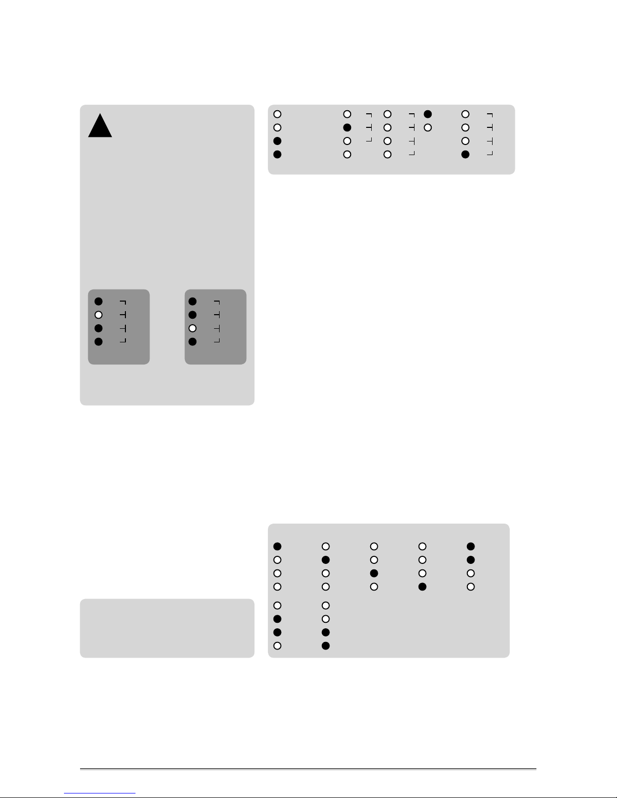
Conversion from four Inputs to four Outputs including the
Sampling Rate Conversion Function
This setting enables to convert four individual input signals to the four
outputs available, as described on page 16.
In the above displayed example, the digital audio input no. 2 (»IN2«) is
selected as clock reference for the internal SRCs.
In the »STATUS« menu the blue LED »LOCK« is lighting and shows that the
SRCs are locked to the externally supplied digital audio signal.
In the »REF CLOCK IN« menu, the last red LED lights in front of »88.2« and
thus shows the clock rate of the externally supplied digital audio signal,
which is then 88.2kHz.
STATUS Menu
This area displays different clock-related conditions of your MC-8 or MC-8.1.
There is no access for changing settings.
»LOCK«
This blue LED lights when the internal PLL circuit has detected the incoming
clock reference signal as valid, or is locked to the internal clock generator. If
the reference signal is unstable or lost, the »LOCK« LED does not light.
»HOLD«
This red LED lights when the external reference clock signal is interrupted
or lost. During this, the Word Clock output signal is continuously available
for stable and reliable synchronization of connected devices.
Furthermore, the HOLD function also enables to run the internal SRCs
interruption-free for continuous signal conversion in cases when the
externally supplied reference signal is interrupted or lost! Due to this, the
conversion function of the whole system is reliably secured.
REF CLOCK IN Menu
This area displays the clock rate of the incoming reference clock signal. The
following basis reference clock rates are supported and will be analyzed:
REFERENCE
88.2
48.0
44.1
32.0
192.0
96.0
176.4
IN3
IN2
IN1
IN4
WCLK
AES11
IN1- 4 → OUT1- 4
IN1 → OUT1/2
IN2 → OUT3/4
IN1
→
OUT1- 4
SRC
MODE
HOLD
LOCK
88.2
48.0
44.1
32.0
192.0
96.0
176.4
STATUS REF CLOCK IN
Locking so-called
»Super Clocks«
Your MC-8 or MC-8.1 is able to lock
to so-called »Super Clock« (SCLK) reference signals. These clock signals are used
preferably for older digidesign ProTools™
MX systems. Specified are only two clock
rates, 11.2896MHz + 12.288MHz which are
the
x
256 multiples of the Word Clock rates
44.1kHz and 48.0kHz.
When locking to one of these Super Clocks,
the rate will be inverted displayed in the
»REF CLOCK IN« menu. Due to this, the LED
in front of the corresponding base clock
rate, that means Word Clock rate, does not
light while all other LEDs light (see examples below).
!
REF CLOCK IN
88.2
48.0
44.1
32.0
192.0
96.0
176.4
Super Clock of
44.1kHz Word
Clock
Super Clock of
48.0kHz Word
Clock
REF CLOCK IN
88.2
48.0
44.1
32.0
192.0
96.0
176.4
32.0kHz
44.1kHz
48.0kHz
88.2kHz
96.0kHz
176.4kHz
192.0kHz
Word Clock Rates
These indications are only available if
the internal PLL circuit is locked stably
to the external reference signal and the
corresponding blue LOCK LED lights
permanently.
Regarding the display of incoming Super Clock rates, please see above on
this page under „Locking so-called »Super Clocks«“.
Page 19
> > > > > > > > > > > > > > > > > > > > > > > > > > > > > > > > > > > > > > > > > > > > > > > > > > > > > > > > > > > > > > > > > > > >
88
\
B E D I E N E L E M E N T E
B E D I E N E L E M E N T E
B E D I E N E L E M E N T E
> > > > > > > > > > > > > > > > > > > > > > > > > > > > > > > > > > > > > > > > > > > > > > > > > > > > > > > > > > > > > > > > > > > >
19
APPENDIX
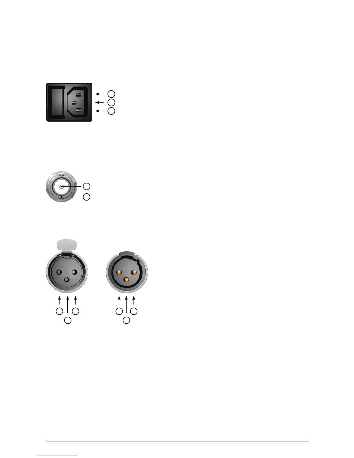
Pin Assignment of the Connectors
Mains
1
1 Neutral (blue; USA: white)
2 Protective earth (green/yellow; USA: green)
3 Live, phase (brown; USA: black)
2
3
1
3
2
1 Ground
2 a conductor (hot / +)
3 b conductor (cold / -)
AES/EBU XLR Output
BNC Input and Output for AES/EBUid,
Word Clock and Super Clock
1 Signal
2 Ground
1
2
2
3
1
1 Audio ground
2 a conductor (hot / +)
3 b conductor (cold / -)
AES/EBU, XLR, Input
Page 20
\\\\\\\\\\\\
A P P E N D I X
A P P E N D I X
A P P E N D I X
> > > > > > > > > > > > > > > > > > > > > > > > > > > > > > > > > > > > > > > > > > > > > > > > > > > > > > > > > > > > > > > > > > > >
> > > > > > > > > > > > > > > > > > > > > > > > > > > > > > > > > > > > > > > > > > > > > > > > > > > > > > > > > > > > > > > > > > > >
88
20
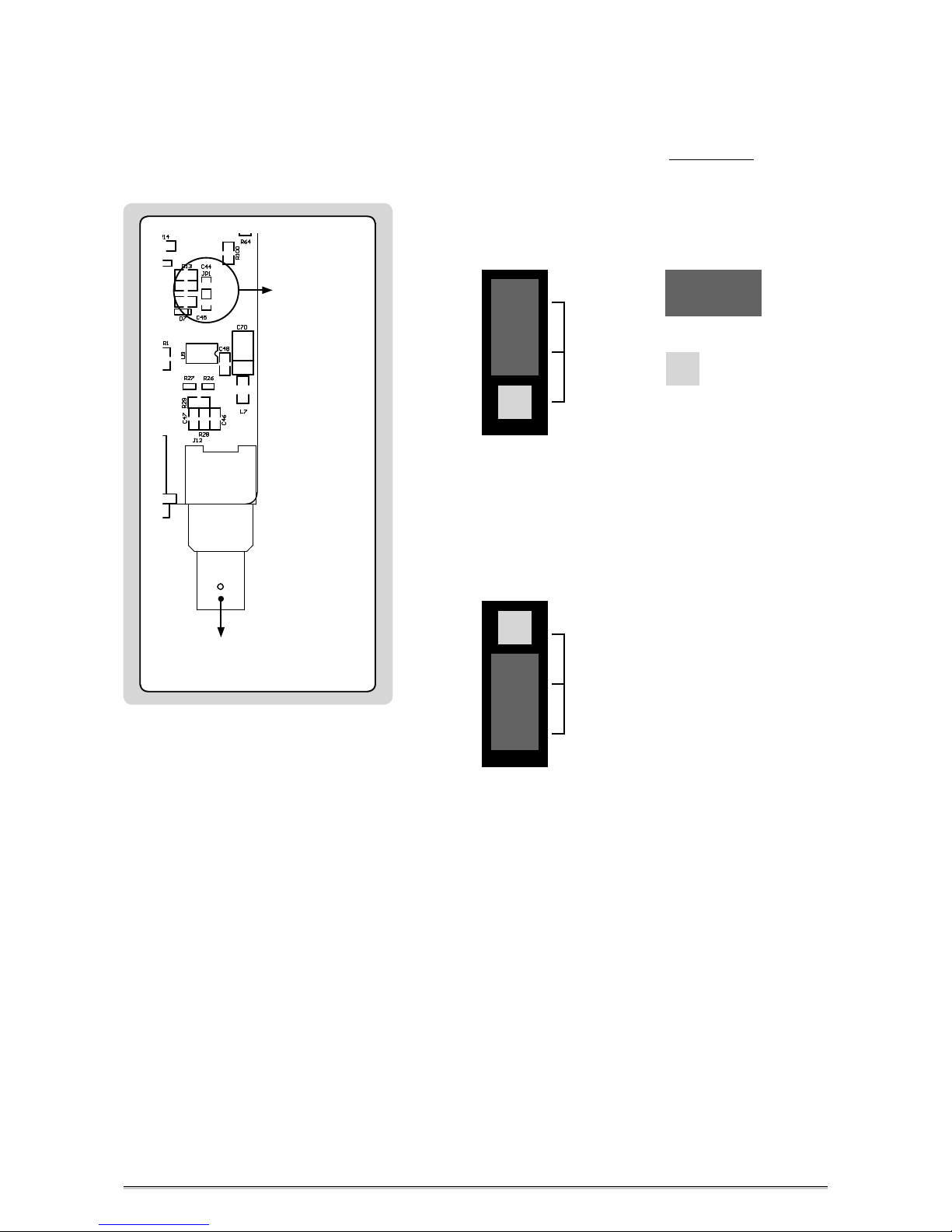
Switching-off the Termination of the Word Clock Input
CAUTION! Disconnect the unit from the mains before opening!
Remount the aluminium cover thoroughly before you attempt to operate
the unit!
When MC-8 or MC-8.1 is shipped, the BNC-based Word Clock input connec
tor is terminated internally with 75 Ω. Therefore, one jumper is put on two
pins - Position 2 - of the 3-pin socket JP1.
When moving the jumper from position 2 to position 1, the input termination will be switched-off. Therefore, the MC-8 or MC-8.1 must be connected
in a chain, in which a device with terminated input follows. Otherwise
you need to use a BNC-T piece in combination with a 75 Ω BNC resistor for
terminating the MC’s input.
JP1
Jumper:
1 2
Free Pin:
Jumper on Position 2
= Termination
For additional information regarding this issue, please refer to page 11.
JP1
1 2
Jumper on Position 1
= no Terminaltion
Word Clock Termination
Termination
3-pin socket
JP1
WCLK
IN / OUT
at front
Page 21

\\\\\\\\\\\\
A P P E N D I X
A P P E N D I X
A P P E N D I X
> > > > > > > > > > > > > > > > > > > > > > > > > > > > > > > > > > > > > > > > > > > > > > > > > > > > > > > > > > > > > > > > > > > >
> > > > > > > > > > > > > > > > > > > > > > > > > > > > > > > > > > > > > > > > > > > > > > > > > > > > > > > > > > > > > > > > > > > >
88
21
Technical Data
WORD CLOCK INPUT (WCLK)
Interface
1 x BNC, 200 mV-7 V, unbalanced, input impedance 75 Ω
Lock Range 25.0kHz to 200.0 kHz, 11.2896MHz + 12.288MHz (so-called Super Clocks)
AES/EBU3/11 INPUT
Interface 1 x XLR female, transformer balanced, input impedance 110 Ω, 200 mV – 7.0 V
Format, Resolution AES3 – 1992/2003, AES11 – 1997/2003, 16 – 24 bits
Lock Range 25.0kHz to 200.0kHz
AES/EBU3/11id INPUT (MC-8.1 only)
Interface 1 x BNC, 200 mV-7 V, unbalanced, input impedance 75 Ω
Format, Resolution AES3id – 1995/2001, 16 – 24 bits
Lock Range 25.0kHz to 200.0kHz
WORD CLOCK OUTPUT (WCLK)
Interface 8 x BNC, 3,5 V @ 22 Ω, unbalanced, buffered
Transmitted Clock Rates 25.0kHz to 200.0kHz
AES/EBU3/11 OUTPUT
Interface 1 x XLR male, transformer balanced, 3.5Vpp @ 110Ω, output impedance 110Ω, buffered
Format, Resolution AES3 – 1992/2003, AES11 – 1997/2003, 24 bits
Transmitted Sampling Rates
25.0kHz to 200.0kHz
AES/EBU3/11id OUTPUT (MC-8 only)
Interface 1 x BNC, 1.0 V, unbalanced, output impedance 75 Ω
Format, Resolution AES3id – 1995/2001, 24 bits
Transmitted Clock Rates 25.0kHz to 200.0kHz
INTERNAL REFERENCE CLOCK SPECIFICATIONS
Oscillator type TCXO, temperature compensated crystal oscillator
Clock accuracy (shipped) < ± 1.0ppm
Clock stability vs. temperature < ± 1.0ppm within -10°C to + 60°C
Operating temperature -10°C to + 60°C
Clock jitter < 10ps (RMS)
POWER SUPPLY
Type
Internal, switching power supply
Input voltage 85V – 264V (automatic adjustment), 47Hz – 440Hz
Power consumption max. 10W
SYSTEM UNIT COVER
Cover size / material / color 196 x 42 x 156mm without connectors (W x H x D), aluminium sheet 1mm, black
Front panel size / material 198 x 44 x 2mm (W x H x D), aluminium
Weight MC-8: ~ 751g, MC-8.1: ~ 748g
Page 22

ALL SOFTWARE AND HARDWARE PRODUCT NAMES ARE REGISTERED TRADEMARKS OF THEIR RESPECTIVE OWNERS.
WE RESERVE THE RIGHT TO CHANGE TECHNICAL DETAILS WITHOUT PRIOR NOTICE.
©
MUTEC GmbH 2002
•
7045-014
WWW.MUTEC-NET.DE
FON 0049-(0)30-746880-0
FAX 0049-(0)30-7468 80-99
> > > > > > > > > > > > > > > > > > > > > > > > > > > > > > > > > > > > > > > > > > > > > > > > > > > > > > > > > > > > >
 Loading...