

Page 1

SD / HD Video Routing Matrix
and Distributor
MUTEC part no. 8015-075
Page 2

Page 3
SAFETY INSTRUCTIONS
!
!
General instruction s
To reduce the risk of fire or electrical shock, do not expose this appliance to rain or moisture, direct
sunlight or excessive heat from sources such as radiators or spotlights. No user serviceable parts are inside. Repair and maintenance must be carried out by qualified personnel authorized by MUTEC GmbH!
The unit has been designed for operation in a standard domestic environment. Do NOT expose the unit
and its accessories to rain, moisture, direct sunlight or excessive heat produced by such heat sources as
radiators or spotlights! The free flow of air inside and around the unit must always be ensured.
C A U T I O N
R I S K O F
ELECTRICAL SHOCK!
Initi al opera tion
Prior to the initi al opera tion of th e unit, t he appli ance, its accessories and packaging m ust be
inspected for any sig ns of phy sical da mage tha t may have occurre d during transit . If the un it has
been damaged m echani cally or if liquid s have be en spill ed inside the enclosure , the appliance ma y
not be co nnected to the mains or mu st be disconne cted f rom the ma ins imm ediate ly! If the unit is
damag ed, please do NOT return i t to MUTEC GmbH, b ut notif y your dealer and the shipping com
pany immediat ely, othe rwis e claim s for dama ge or replaceme nt may not b e grante d.
If the device is left in a low-temperature environment for a long time and then is moved to a roomtemperature environment, condensation may occur on the inside and the exterior. To avoid shortcircuits and flashovers, be sure to wait one or two hours before putting the device into operation.
Power su pply
The device contains a self-adapting wide-range power supply supporting the majority of global standard line voltages within a range of 90…250 V, with no need for making adjustments. Make sure that
your line-voltage source provides a supply voltage within the specified range. In addition, make sure
that the device is properly grounded via the local electric installation.
Pleas e use the e nclos ed powe r cord (s ee packaging) to connec t the uni t to the mains. Swi tch the
unit of f befor e you att empt to co nnec t it to the ma ins. Co nnect the powe r cord to th e unit, then
to a standard 3-pin mai ns outl et. To draw th e power cord, nev er pull on the cable b ut on the m ains
plug!
The uni t must be grounded during operat ion!
For information on the power-inlet wiring, refer to the »Wirin g of conne ctor s« section in the
appendix. Disconnect the device from the mains when not using it for an extended period!
-
Decla ration o f Confor mity
We herewith confirm that the product complies with the European
Commission’s standards on electromagnetic compatibility.
Interference emission: EN 50081-1, 1992
Resistance to interference: EN 50082-1, 1992
Presupposed as operation condition is that all clock outputs are connected with high-quality and good shielded BNC 75 ohms cable.
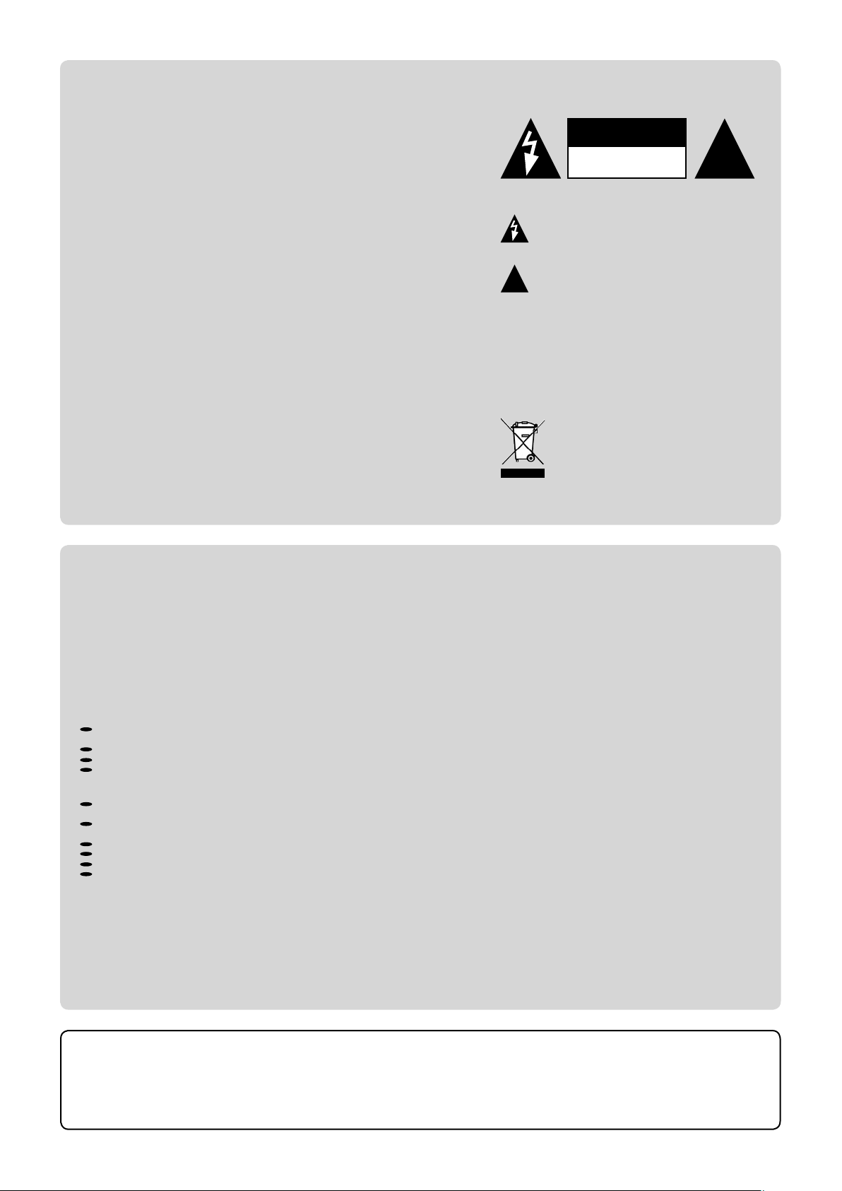
This symbol, a flash of lightning inside a triangle, alerts
you to the presence of uninsulated dangerous voltage
inside the enclosure - voltage that may be sufficient to
constitute a risk of shock.
This symbol, an exclamation mark inside a triangle,
alerts you to important operating or safety instructions
in this manual.
WARRANTY REGULATIONS
§1 Warranty
MUTEC GmbH warrants the flawless performance of this product to the original buyer for a period of two (2) years from the date of purchase. If any failure occurs within
the specified warranty period that is caused by defects in material and/or workmanship, MUTEC GmbH shall either repair or replace the product free of charge within 90
days. The purchaser is not entitled to claim an inspection of the device free of charge during the warranty period. If the warranty claim proves to be justified, the product
will be returned freight prepaid by MUTEC GmbH within Germany. Outside Germany, the product will be returned with the additional international freight charges payable
by the customer. Warranty claims other than those indicated above are expressly excluded.
§2 Warranty transferabili ty
This warranty is extended exclusively to the original buyer who bought the product from a MUTEC GmbH specialized dealer or distributor, and is not transferable to anyone
who may subsequently purchase this product. No other person (retail dealer, distributor, etc.) shall be entitled to give any warranty promise on behalf of MUTEC GmbH.
§3 Waranty regulations
The return of the completed registration card, or online registration on one of the websites specified below, is a condition of warranty. Failing to register the device before
returning it for repair will void the extended warranty.
The serial number on the returned device must match the one stated on the registration card or entered during online registration. Otherwise, the device will be
returned to the sender at the sender’s expense.
Any returned device must be accompanied by a detailed error description and a copy of the original sales receipt issued by a MUTEC dealer or distributor.
The device must be returned free of shipping expenses and in the original package, if possible; otherwise, the sender has to provide comparably protective packaging.
The sender is fully responsible for any damage or loss of the product when shipping it to MUTEC GmbH.
§4 Limitation of warranty
Damages caus ed by the followin g condit ions are not cover ed by this warrant y:
Damages caus ed by every kind of normal wear and tea r (e.g. di splay s, LED s, pote ntiometers , fader s, switches , but tons, c onnec ting element s, prin ted labels, cover
glass es, cover prin ts, and similar p arts).
Functional failure of th e product caused by improper i nsta llation (please obse rve CM OS components handlin g instr uctions!) , negle ct or mi suse of
the pro duct , e.g. failure to operate the unit in compliance with the instructio ns give n in the user or ser vice ma nuals .
Damage cause d by any for m of external mechanical impac t or modification.
Damage cause d by the us er’s failure to con nect a nd opera te the uni t in compl iance wi th local safet y regulations .
Damage cause d by force m ajeure (fire, ex plosi on, flood, ligh tning, war, vandali sm, et c.) .
Consequential damages or defect s in products f rom other manufa cturers as wel l as any cos ts res ulting f rom a los s of productio n.
Repair s carried out by p erso nnel which is not au thorized from MU TEC Gmb H will void t he warranty.
national, technical, or safety regulations in a country or of the customer do not constitute a warranty claim and should be set with MUTEC GmbH in advance.
§5 Repairs
To obtain warranty service, the buyer must call or write to MUTEC GmbH before returning the unit. All inquiries must be accompanied by a description of the problem and
the original buyer’s invoice. Devices shipped to MUTEC GmbH for repair without prior notice will be returned to the sender at the sender’s expense.
failure please contact:
Adaptations and modifications to the device made with regard to
In case of a functional
MUTEC Gesellschaf t fuer Systemen twicklung und Kompone ntenver trie b mbH
Siekeweg 6/8 • 12 309 Berlin • Ger many • Fon 0 30-74 688 0- 0 • Fax 030 -7468 80- 99 • Tecsupport@MUTEC-net.de • www.MUTEC-net.de
MUTEC GmbH assumes no liability for any incorrect information given in this manual. Please note that
all software/hardware product names are registered trademarks of their respective owners. No part of
this manual may be reproduced, copied or converted to a machine-readable form or electronical media
without a written permission of MUTEC GmbH. We reserve the right to change or improve our products
without notice.
MUTEC GmbH 20 08
©
Page 4

Page 5

CONTENT
INTRODUCTION
General Function Description . . . . . . . . . . . . . . . . . 7
Features . . . . . . . . . . . . . . . . . . . . . . . . . . . . .
Applications . . . . . . . . . . . . . . . . . . . . . . . . . . . 8
Peripheral Products . . . . . . . . . . . . . . . . . . . . . . .
8
8
CONTROL ELEMENTS
MC-5 Front Panel . . . . . . . . . . . . . . . . . . . . . . . . 9
MC-5 Rear Panel
. . . . . . . . . . . . . . . . . . . . . . . . 10
INSTALLATION
Content of the Box . . . . . . . . . . . . . . . . . . . . . . . 11
Placing the Device . . . . . . . . . . . . . . . . . . . . . . . 11
Wiring the Video Interfaces
. . . . . . . . . . . . . . . . . . 11
GENERAL OPERATION
Selecting Function Menus and setting Functions . . . . . . 13
Steps of Operation . . . . . . . . . . . . . . . . . . . . . . . 13
OPERATING THE MC-5
PRESET . . . . . . . . . . . . . . . . . . . . . . . . . . . . . 14
ROUTING MATRIX OUTPUT
. . . . . . . . . . . . . . . . . . 14
APPENDIX
Pin Assignment of the Connectors . . . . . . . . . . . . . . 15
Technical Data . . . . . . . . . . . . . . . . . . . . . . . . . 16
Page 6

Page 7

B E D I E N E L E M E N T E
!
B E D I E N E L E M E N T E
B E D I E N E L E M E N T E
\
> > > > > > > > > > > > > > > > > > > > > > > > > > > > > > > > > > > > > > > > > > > > > > > > > > > > > > > > > > > > > > > > > > > >
INTRODUCTION
Thank you for purchasing the MC-5,
Distributor, from MUTEC GmbH.
Please keep this manual for future reference!
General Function Description
The MC-5 is an extremely high-flexible routing matrix and distributor for
standard definition (SD) bi-level and high definition (HD) tri-level video
signals.
The unit offers simultaneous routing and distribution of SD and HD video
signals, regardless of the frame rates and formats of the incoming video
references. In this process, the input signals are distributed according to
your settings directly to the selected outputs without any alteration or
amplification.
For this, the MC-5 provides 4 BNC inputs which can be routed individually
to12 BNC outputs. One input reference signal can be distributed to one, but
also on up to 12 outputs. When inputing more signals the available number
of outputs will be reduced accordingly. But due to the routing capabilities
of MC-5, the number of the outputs for the individual input signals can be
assigned free.
Additionally, the unit offers a preset management which allows to store
and to switch over 4 different settings of all outputs. So, MC-5 enables to
configure the exact needed number of outputs for every video distribution
application very easily.
A new designed, simple user interface enables to install the MC-5 without
longer training time. Thus, the MC-5 provides an ideal output expansion for
MUTEC’s video clock generator products, e.g. iCLOCK, iCLOCKdp, MC-3.1,
MC-3.2 and MC-3.3.
SD/HD Video Routing Matrix and
The grey boxes contain supplementary
informationen for the corresponding
sections in the text columns. The content of
the individual box refers to the description
in the text column beside the box.
Boxes which contain a triangle with
an exclamation mark inside should
be read carefully!
additional information which are of major
importance for the functional descriptions
in the text column.
These include
> > > > > > > > > > > > > > > > > > > > > > > > > > > > > > > > > > > > > > > > > > > > > > > > > > > > > > > > > > > > > > > > > > > >
88
7
Page 8

I N T R O D U C T I O N
I N T R O D U C T I O N
I N T R O D U C T I O N
\\\\\\\\\\\\
> > > > > > > > > > > > > > > > > > > > > > > > > > > > > > > > > > > > > > > > > > > > > > > > > > > > > > > > > > > > > > > > > > > >
Features
Routing matrix and signal distribution functionalities in one box
Compatible to HD tri-level and SD bi-level PAL, NTSC, SECAM
Accepts four independent video input signals simultaneously
Built-in 4-way preset management
Distributes HD test pattern component signals
All adjustments are retained after power-down.
Simple, new user interface.
Built-in international power supply.
Applications
Stellate SD video and HD tri-level signal distribution
Mixed video signal distribution
Free assignment of the outputs to the individual inputs
Distribution of HD test pattern component signals
Output expansion for MUTEC‘s iCLOCK, iCLOCKdp, MC-3.1, MC-3.2 and
MC-3.3
Peripheral Products
iCLOCK + iCLOCKdp
iCLOCK and iCLOCKdp are synchronizable, high-precision clock generators
which are designed to be the reference in digital audio and video studios as
well as broadcast and television stations. For further details please visit:
www.iCLOCK-NET.de
MC-3.1
The MC-3.1 SMART CLOCK SD is an universal digital audio and SD video
sync master clock generator. The unit provides different high-stable clock
signals for simultaneous synchronization of digital audio and SD video
devices.
MC-3.2
The MC-3.2 SMART CLOCK HD is an universal digital audio and SD/HD video
sync master clock generator. The unit provides different high-stable clock
signals for simultaneous synchronization of digital audio and SD/HD video
devices.
MC-3.3
The MC-3.3 SMART CLOCK VR is an universal and high accurate SD/HD video
sync master clock generator. This unit supplies different high-stable SD bilevel and HD tri-level reference signals for simultaneous synchronization of
SD/HD video devices in television stations, video editing suits or film/video
copy studios.
For all peripheral products please have a look on our website:
www.MUTEC-NET.de !
88
> > > > > > > > > > > > > > > > > > > > > > > > > > > > > > > > > > > > > > > > > > > > > > > > > > > > > > > > > > > > > > > > > > > >
8
Page 9

B E D I E N E L E M E N T E
B E D I E N E L E M E N T E
B E D I E N E L E M E N T E
\
> > > > > > > > > > > > > > > > > > > > > > > > > > > > > > > > > > > > > > > > > > > > > > > > > > > > > > > > > > > > > > > > > > > >
CONTROL ELEMENTS
MC-5 Front Panel
3
2
1
1 POWER
This red LED lights up when the unit is switched on with the rear panel
POWER switch (on condition that the adjusted voltage matches your local
voltage).
2 MENU
Use this key to access the different function menus.
3 SELECT
Use this key to select a function from a specific function menu.
4 PRESET
This functional menu lets you choose one of the four available output
presets.
5 ROUTING MATRIX OUTPUT
Within this functional menu you can route the four inputs individually to
the 12 outputs.
MC-5 Rear Panel
4
5
Refer to the OPERATIONS chapter for more
information.
For detailed specifications on all terminals,
refer to the »Pin Assignment of the
Connectors« and »Technical Data« in the
chapter APPENDIX.
1
1 SD/HD VIDEO OUT
These outputs transfers SD bi-level or HD tri-level video signals. Every of the
four inputs can be individually assigned to one or more of these outputs.
For adjusting these outputs see chapter OPERATION.
2 SD/HD VIDEO IN
This inputs can receive SD bi-level or HD tri-level video signals. They can be
indivudually routed to one or more of the 12 outputs. For routing of these
inputs see chapter OPERATION.
3 MAINS IN, Power Switch + Mains connector (IEC)
This is the main switch for switching the device on and off. Connect the
supplied IEC power cable to the device‘s mains connector. Make sure that
the power switch is turned off before connecting the device to your power
source finally. Line voltages within the range of 90…260 V with a frequency
of 50 or 60 Hz can be applied. The internal power supply will automatically
make all necessary adjustments.
Heed the SAFETY INSTRUCTIONS at the beginning of this manual!
> > > > > > > > > > > > > > > > > > > > > > > > > > > > > > > > > > > > > > > > > > > > > > > > > > > > > > > > > > > > > > > > > > > >
2
3
88
9
Page 10

Page 11

B E D I E N E L E M E N T E
!
!
!
!
B E D I E N E L E M E N T E
B E D I E N E L E M E N T E
\
> > > > > > > > > > > > > > > > > > > > > > > > > > > > > > > > > > > > > > > > > > > > > > > > > > > > > > > > > > > > > > > > > > > >
INSTALLATION
Content of the Box
The unit was packed carefully. Nevertheless we recommend to check the
content directly after opening the package:
1 x MC-5
1 x Power cable
1 x Manual
4 x Rubber feets
1 x Registration card
Placing the Device
The unit should be set up as closely as possible to the devices to which it
will be connected, so as to avoid excessive cable lengths. Use the 4 rubber
feets enclosed with the appliance and stick them symmetrically on the
bottom side of the unit to protect the enclosure and supporting surface
from being damaged. When the unit is installed in a rack, the rubber feets
cannot be attached to save space.
The device can be mounted into a standard 19“ rack and will require one
unit. For this installation MUTEC offers an optional set of rack ears (MW05/19, order no. 8020-035). The mounting depth including the terminals is
175mm/6.9“. Another 150mm/5.9“ should be added for the required cables.
Additional slide-in rails on the rack inside are recommended for safe installation. This will also avoid long-term mechanical deformation of the housing.
If there are any damages please refer to
SAFETY INSTRUCTIONS, Initial Operation,
and WARRANTY REGULATIONS.
should be read carefully.
produced by radiators, heaters, or spot
lights! Sufficient air circulation in the
environment of the device must be ensured!
The condition of the packaging
material and the device should
be checked carefully additionally.
Before installing the unit the section
SAFETY INSTRUCTIONS located
at the beginning of this manual
Never expose the device and
accessories to rain, moisture,
direct sunlight, or excessive heat
Wiring the Video Interfaces
To allow for the distribution of signals, the interfaces of all devices involved
must be properly connected to each other, so as to ensure a logical signal
flow. Always be sure to connect the video outputs of the MC-5 to the corresponding inputs of the devices you wish to feed with the distributed video
signal. Cable lengths should be kept as short as possible to minimize signal
losses and/or interferences!
For the transmission of video signals electrical, unsymmetrical cables with a
resistance of 75 Ω and BNC connectors on both ends are used. Typically, such
cables are marked »RG-59U, RG59B/U«.
Additionally, you should make sure that the video inputs to be connected
to the MC-5’s outputs have a 75
allow for enabling/disabling the termination with a so-called »terminationswitch«, which may be located on the outside or inside of the device.
For devices which have no termination of the video input, you can use an
additional BNC-T piece to terminate the input. Plug the T piece with its
center connector into the input of the receiving device. Then, connect the
cable coming from the MC-5 to one of the lateral connectors, and the other
connector of the BNC-T piece to a 75 Ω resistor forming the BNC termina-
tion.
Basically, you should avoid »looping through« video leads by means of
passive BNC-T pieces to preserve the signal quality, as level drops will be the
result. If there is no other way to wire your set-up, please make sure that all
video inputs (except for the last device in the chain) have their terminations
disabled! In a serial video chain only the last clock input should have a termination! Never connect more than three devices in series to one output!
Ω terminating resistor! Most video inputs
It is imperative that the lengths
of all cables connected are largely
the same, as this is the only way to
ensure that all devices will be synchronized
or feeded in phase (exception: cable tolerances).
Please make sure that the cable used has a
resistance of 75 Ω, in compliance with the
specifications! If a cable with a different
resistance is used, a dramatic deterioration
of the signal quality can be the result! In
this case, the perfect synchronization or
feeding of all devices involved could be
impaired.
> > > > > > > > > > > > > > > > > > > > > > > > > > > > > > > > > > > > > > > > > > > > > > > > > > > > > > > > > > > > > > > > > > > >
88
11
Page 12

Page 13

B E D I E N E L E M E N T E
!
B E D I E N E L E M E N T E
B E D I E N E L E M E N T E
\
> > > > > > > > > > > > > > > > > > > > > > > > > > > > > > > > > > > > > > > > > > > > > > > > > > > > > > > > > > > > > > > > > > > >
GENERAL OPERATION
Selecting Function Menus and setting Functions
Operating the MC-5 is very simple! The device is fully operated using the 2
keys at the front panel.
1 Switching the MENU key toggles between different basic function menus.
2 Switching the SELECT key activtes individual functions within one
function menu.
2. SELECT
selects individual
1. MENU
function menus.
MENU + SELECT operation
selects individual
functions within
one function
area.
Menus
Menus
Functions
Functions
Steps of Operation
1 First press on MENU or SELECT key enables the last selected function
within the last selected function menu. The corresponding LED is
beginning to flash.
2 Every press on SELECT key will select a new function. The LED of every
selected function will flash accordingly and the corresponding function is
available at once.
3 When the needed function is selected, do not press the switches again!
After a period of approx. 4 seconds the LED in front of the selected
function will stop flashing.
All user-specific function settings
are available furthermore when
power is restored.
> > > > > > > > > > > > > > > > > > > > > > > > > > > > > > > > > > > > > > > > > > > > > > > > > > > > > > > > > > > > > > > > > > > >
88
13
Page 14

O P E R AT I O N
!
!
O P E R AT I O N
O P E R AT I O N
\\\\\\\\\\\\
> > > > > > > > > > > > > > > > > > > > > > > > > > > > > > > > > > > > > > > > > > > > > > > > > > > > > > > > > > > > > > > > > > > >
OPERATING THE MC-5
PRESET
This menu enables you to set and to store four different set-ups of output
configurations. Its operation is very easy.
Choose one of the four presets (SET1 – 4) by pressing the SELECT button
repeatedly. When the desired preset is selected, define your output
configuration by setting the corresponding LEDs in the ROUTING MATRIX
OUTPUT menu (see below). After routing the inputs to the outputs, the
whole output configuration will be stored under the selected preset
number.
For programming of an other preset, choose a new preset number and
repeat the previously mentioned steps.
For changes within a preset configuration, select the preset which needs
to be modified and change the input routing in the ROUTING MATRIX
OUTPUT menu accordingly. This changes will be automatically stored under
PRESET
ROUTING MATRIX OUTPUT
The MC-5 does not allow to
combine two input signals and to
distribute these to one output. If
one input is assigned to one or multiple
outputs, these outputs can be not used for
other input signals at the same time!
The MC-5 does not supply any form
of redundancy or failure safety
for the output signals! When e.g.,
the video signals which are supplied at the
inputs fail, the output signals are also lost
in the same moment!
the selected preset number.
The factory default is set to SET 1.
ROUTING MATRIX OUTPUT
This menu enables you to route the four inputs individually to the 12
outputs. Thus, SD and HD video signals, regardless of their frame rates and
formats, can be routed and distributed simultaneously. For distributing
HD test pattern signals, you have to choose for every component signal a
separate input. Please make sure that the outputs are adjusted accordingly
to transmit the component signals correctly!
In this process, the input signals are distributed without any alteration or
amplification.
One input signal can be routed to one output, to multiple outputs, but also
to all 12 outputs. If more than one input signal is supplied, the number of
assigned outputs to the corresponding inputs can be different.
For assigning an input to an output, select the corresponding output menu
by pressing the MENU button repeatedly. Than press the SELECT button
to route one of the inputs IN1 – 4 to the selected output. The LED of the
currently active input of the selected output is blinking. If you press the
SELECT button furthermore and all four LEDs are blinking simultaneously,
the output can be switched off. After this adjustment is stored, no LED
lights under the corresponding output number.
The factory default is set that input IN 1 distributes to all 12 outputs.
88
> > > > > > > > > > > > > > > > > > > > > > > > > > > > > > > > > > > > > > > > > > > > > > > > > > > > > > > > > > > > > > > > > > > >
14
Page 15

B E D I E N E L E M E N T E
B E D I E N E L E M E N T E
B E D I E N E L E M E N T E
\
> > > > > > > > > > > > > > > > > > > > > > > > > > > > > > > > > > > > > > > > > > > > > > > > > > > > > > > > > > > > > > > > > > > >
APPENDIX
Pin Assignment of the Connectors
Mains
3
2
1
1 Neutral (blue; USA: white)
2 Protective earth (green/yellow; USA: green)
3 Live, phase (brown; USA: black)
SD/HD Video BNC Input and Output
1
1 Signal
2 Ground
2
> > > > > > > > > > > > > > > > > > > > > > > > > > > > > > > > > > > > > > > > > > > > > > > > > > > > > > > > > > > > > > > > > > > >
88
15
Page 16

A P P E N D I X
A P P E N D I X
A P P E N D I X
\\\\\\\\\\\\
> > > > > > > > > > > > > > > > > > > > > > > > > > > > > > > > > > > > > > > > > > > > > > > > > > > > > > > > > > > > > > > > > > > >
Technical Data
SD/HD VIDEO IN 1 – 4
Interface 4 x BNC female, unbalanced input impedance 75 Ω
Input Level Range 0.2 – 5.0 V (p-p)
Video Input Formats
SD/HD VIDEO OUT 1 – 12
Interface 12 x BNC female, unbalanced, output impedance 75Ω, individually buffered
Output Level 0.2 – 5.0 V (p-p), no amplification
Video Output Formats
SIGNAL PROCESSING
Signal processes No alteration, no amplification
POWER SUPPLY
Type
Input voltage 90 V – 260 V (automatic adjustment), 47 Hz – 440 Hz
Power consumption max. 10 W
SYSTEM UNIT COVER
Cover size / material / color 196 x 42 x 156mm without connectors (W x H x D), aluminium sheet 1mm, black
Front panel size / material 198 x 44 x 2mm (W x H x D), aluminium
Weight ~ 800g
SD bi-level (PAL / SECAM + NTSC), HD tri-level, all video standard and frame rate combinations
SD bi-level (PAL / SECAM + NTSC), HD tri-level, all video standard and frame rate combinations
Internal switching power supply
88
> > > > > > > > > > > > > > > > > > > > > > > > > > > > > > > > > > > > > > > > > > > > > > > > > > > > > > > > > > > > > > > > > > > >
16
Page 17

17
Page 18

> > > > > > > > > > > > > > > > > > > > > > > > > > > > > > > > > > > > > > > > > > > > > > > > > > > > > > > > > > > > >
ALL SOFTWARE AND HARDWARE PRODUCT NAMES ARE REGISTERED TRADEMARKS OF THEIR RESPECTIVE OWNERS.
WE RESERVE THE RIGHT TO CHANGE TECHNICAL DETAILS WITHOUT PRIOR NOTICE.
MUTEC GmbH 2002
©
•
7045-014
FON 0049-(0)30-746880-0
FAX 0049-(0)30-7468 80-99
WWW.MUTEC-NET.DE
 Loading...