

Page 1
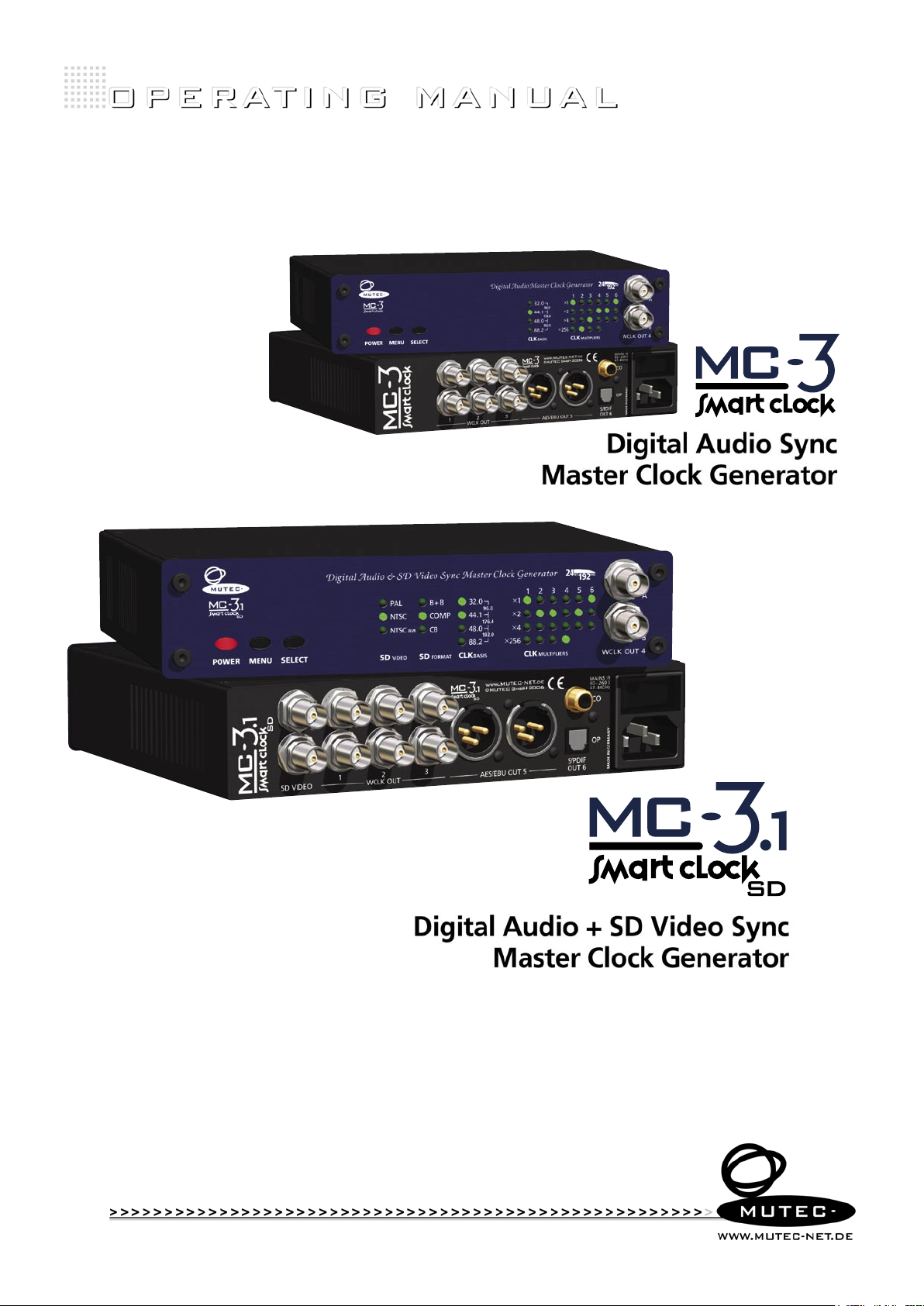
Digital Audio Sync
Master Clock Generator
Digital Audio + SD Video Sync
MUTEC part no. 8015-065 (MC-3) + 8015-066 (MC-3.1)
Master Clock Generator
Page 2

Page 3
SAFETY INSTRUCTIONS
!
!
General instructions
To reduce the risk of fire or electrical shock, do not expose this appliance to rain or moisture, direct
sunlight or excessive heat from sources such as radiators or spotlights. No user serviceable parts are inside. Repair and maintenance must be carried out by qualified personnel authorized by MUTEC GmbH!
The unit has been designed for operation in a standard domestic environment. Do NOT expose the unit
and its accessories to rain, moisture, direct sunlight or excessive heat produced by such heat sources as
radiators or spotlights! The free flow of air inside and around the unit must always be ensured.
C A U T I O N
R I S K O F
ELECTRICAL SHOCK!
Initi al operation
Prior to the initial operatio n of the unit, th e appli ance, i ts acc essories a nd packaging m ust be
inspecte d for any s igns of physi cal damage tha t may have occurred during transit . If the un it has
been damage d mechanically or if li quids have be en spilled inside the enclo sure, the appliance may
not be co nnec ted to the mains or mus t be dis conne cte d from th e mains i mmed iatel y! If the unit is
damag ed, pl ease do NOT ret urn it to M UTEC G mbH, b ut noti fy you r deale r and the shipping com
pany immedia tely, ot her wise claims for dama ge or replace ment may not be granted .
If the device is left in a low-temperature environment for a long time and then is moved to a roomtemperature environment, condensation may occur on the inside and the exterior. To avoid shortcircuits and flashovers, be sure to wait one or two hours before putting the device into operation.
Power su pply
The device contains a self-adapting wide-range power supply supporting the majority of global standard line voltages within a range of 90…250 V, with no need for making adjustments. Make sure that
your line-voltage source provides a supply voltage within the specified range. In addition, make sure
that the device is properly grounded via the local electric installation.
Pleas e use th e enclo sed power cord (se e packaging) to conne ct th e unit to the mains. Swi tch the
unit of f befo re you at tempt to conn ect i t to the ma ins. C onnect the p ower co rd to the u nit, then
to a standard 3 -pin mains outlet . To draw the p ower cord, ne ver pull on the ca ble but on the mains
plug!
The uni t must b e grounded during op erati on!
For information on the power-inlet wiring, refer to the »Wirin g of conn ectors« section in the
appendix. Disconnect the device from the mains when not using it for an extended period!
-
Decla ratio n of Conf ormit y
We herewith confirm that the product complies with the European
Commission’s standards on electromagnetic compatibility.
Interference emission: EN 50081-1, 1992
Resistance to interference: EN 50082-1, 1992
Presupposed as operation condition is that all clock outputs are connected with high-quality and good shielded BNC 75 ohms cable.
This symbol, a flash of lightning inside a triangle, alerts
you to the presence of uninsulated dangerous voltage
inside the enclosure - voltage that may be sufficient to
constitute a risk of shock.
This symbol, an exclamation mark inside a triangle,
alerts you to important operating or safety instructions
in this manual.
WARRANTY REGULATIONS
§1 Warranty
MUTEC GmbH warrants the flawless performance of this product to the original buyer for a period of two (2) years from the date of purchase. If any failure occurs within
the specified warranty period that is caused by defects in material and/or workmanship, MUTEC GmbH shall either repair or replace the product free of charge within 90
days. The purchaser is not entitled to claim an inspection of the device free of charge during the warranty period. If the warranty claim proves to be justified, the product
will be returned freight prepaid by MUTEC GmbH within Germany. Outside Germany, the product will be returned with the additional international freight charges payable
by the customer. Warranty claims other than those indicated above are expressly excluded.
§2 Warranty transferability
This warranty is extended exclusively to the original buyer who bought the product from a MUTEC GmbH specialized dealer or distributor, and is not transferable to anyone
who may subsequently purchase this product. No other person (retail dealer, distributor, etc.) shall be entitled to give any warranty promise on behalf of MUTEC GmbH.
§3 Waranty regulations
The return of the completed registration card, or online registration on one of the websites specified below, is a condition of warranty. Failing to register the device before
returning it for repair will void the extended warranty.
The serial number on the returned device must match the one stated on the registration card or entered during online registration. Otherwise, the device will be
returned to the sender at the sender’s expense.
Any returned device must be accompanied by a detailed error description and a copy of the original sales receipt issued by a MUTEC dealer or distributor.
The device must be returned free of shipping expenses and in the original package, if possible; otherwise, the sender has to provide comparably protective packaging.
The sender is fully responsible for any damage or loss of the product when shipping it to MUTEC GmbH.
§4 Limitation of warranty
Damages cau sed by the follo wing co nditi ons are not cove red by th is warranty :
Damages cau sed by every k ind of no rmal wear and tea r (e.g. displ ays, L EDs, poten tiometers, faders, swit ches , but tons , conne ctin g elem ents , prin ted lab els, cover
glass es, c over pr ints , and similar pa rts).
Functional f ailure o f the pro duc t caus ed by imprope r installation (p leas e obse rve C MOS com ponents han dling instr uctions!), ne glec t or mis use of
the pro duct, e.g. failure to operate the unit in complian ce with the ins truc tion s give n in the us er or servi ce manu als.
Damage caused by any form of ex ternal mechanical impa ct or modifi catio n.
Damage caused by the u ser ’s failure to conn ect a nd operate the u nit in co mplia nce wit h local safety regulations.
Damage caused by for ce majeure (fire, explosi on, flood, li ghtni ng, war, vandalism, et c.) .
Consequen tial damages o r defe cts i n product s from other manufac turers as wel l as any co sts result ing fro m a loss of producti on.
Repair s carried ou t by per sonn el which is not au thori zed fro m MUTEC GmbH wi ll void th e warranty.
national, technical, or safety regulations in a country or of the customer do not constitute a warranty claim and should be set with MUTEC GmbH in advance.
§5 Repairs
To obtain warranty service, the buyer must call or write to MUTEC GmbH before returning the unit. All inquiries must be accompanied by a description of the problem and
the original buyer’s invoice. Devices shipped to MUTEC GmbH for repair without prior notice will be returned to the sender at the sender’s expense.
failure please contact:
Adaptations and modifications to the device made with regard to
In case of a functional
MUTEC Gesellschaft fu er Syst ement wicklung und Kompo nente nvert rieb mbH
Siekeweg 6/8 • 12309 B erli n • Germany • Fon 030-74 688 0- 0 • Fax 030-746 880 -99 • Tecsuppo rt@MUTEC-net.com • www.MUTEC-net.com
MUTEC GmbH assumes no liability for any incorrect information given in this manual. Please note that
all software/hardware product names are registered trademarks of their respective owners. No part of
this manual may be reproduced, copied or converted to a machine-readable form or electronical media
without a written permission of MUTEC GmbH. We reserve the right to change or improve our products
without notice.
MUTEC GmbH 2 00 6 –2012
©
Page 4

Page 5

CONTENT
INTRODUCTION
General Function Description . . . . . . . . . . . . . . . . . 7
Features . . . . . . . . . . . . . . . . . . . . . . . . . . . . .
Applications . . . . . . . . . . . . . . . . . . . . . . . . . . . 8
Peripheral MUTEC Products
. . . . . . . . . . . . . . . . . . 8
7
CONTROL ELEMENTS AND TERMINALS
MC-3 SMART CLOCK Front Panel . . . . . . . . . . . . . . . 9
MC-3.1 SMART CLOCK SD Front Panel
MC-3 SMART CLOCK Rear Panel . . . . . . . . . . . . . . . .
MC-3.1 SMART CLOCK SD Rear Panel
. . . . . . . . . . . . 9
10
. . . . . . . . . . . . . 10
INSTALLATION
Content of the Box . . . . . . . . . . . . . . . . . . . . . . . 11
Placing the Device . . . . . . . . . . . . . . . . . . . . . . . 11
Wiring the Word Clock and Video Interfaces . . . . . . . . .
Wiring the AES/EBU and S/PDIF Interfaces . . . . . . . . . . 12
11
GENERAL OPERATION
Selecting Function Menus and setting Functions . . . . . . 13
Steps of Operation . . . . . . . . . . . . . . . . . . . . . . . 13
MC-3 + MC-3.1 AUDIO CLOCK SETTINGS
CLK BASIS . . . . . . . . . . . . . . . . . . . . . . . . . . . . . 14
CLK MULTIPLIERS . . . . . . . . . . . . . . . . . . . . . . . . . . 14
MC-3.1 SD VIDEO SETTINGS
SD VIDEO . . . . . . . . . . . . . . . . . . . . . . . . . . . . . 15
SD FORMAT . . . . . . . . . . . . . . . . . . . . . . . . . . . . 15
Video and Audio Signal Relations . . . . . . . . . . . . . . 15
APPENDIX
Pin Assignment of the Connectors . . . . . . . . . . . . . . 17
Technical Data
Generatable Word Clock (WCLK) Frequencies . . . . . . . . 19
Generatable AES/EBU and S/PDIF Frequencies . . . . . . . . 19
. . . . . . . . . . . . . . . . . . . . . . . . . 18
Page 6

Page 7

B E D I E N E L E M E N T E
!
!
B E D I E N E L E M E N T E
B E D I E N E L E M E N T E
\
> > > > > > > > > > > > > > > > > > > > > > > > > > > > > > > > > > > > > > > > > > > > > > > > > > > > > > > > > > > > > > > > > > > >
INTRODUCTION
Thank you for purchasing a MC-3 SMART CLOCK or MC-3.1 SMART CLOCK SD,
Digital Audio & Video Sync Master Clock Generator from MUTEC GmbH.
Please keep this manual for future reference!
General Function Description
SMART CLOCK and SMART CLOCK SD generate different clock signals for
synchronization of digital audio and SD video devices such as hard-disk
recorders, A/V workstations, digital mixing consoles, AD/DA converters,
musical instruments and sound cards. Simultaneous use of all available
clock signals enables each device in the recording studio to be individually
synchronized. In addition, different clock rates of all audio-related clock
signals can be simultaneously output. Thus, new devices with higher clock
rates may be integrated into an existing studio set-up without difficulty. It
is also possible to supply various workstations in the same room with differ
ent clock rates.
MC-3 SMART CLOCK offers 7 basis Ultra low-jitter Word Clocks from 32.0kHz
up to 192.0kHz
output pairs with multipliers x1, x2 and x4 for a maximum clock rate of
768.0kHz. For the synchronization of older digidesign ProTools™ systems,
the respec-tive Word Clock frequencies can be transferred as Word Clock x
256 (also called Super Clock). AES/EBU and S/PDIF (optical + coaxial) blank
frame sync signals are available from 32.0kHz up to 192.0kHz.
Every Word Clock output pair as well as the AES/EBU and S/PDIF outputs can
be set to a different clock rate, based on one common clock frequency.
MC-3.1 SMART CLOCK SD offers same audio clock functionalities like
MC-3 SMART CLOCK, but includes a standard definition (SD) video sync
reference generator supporting PAL or NTSC SD video sync signals as
Black + Burst or composite sync as well as the respective color bars. Two
additional video outputs are available on the rear side of the housing. Thus,
audio clocks and video sync references are all available at the same time to
synchronize complete audio/video facilities.
The design advantage of the SMART CLOCKs is its high-precision frequency
generator, from which all clock signals are simultaneously derived. As a
result, the individual clock signals generated are synchronized to each other
in phase, and hence feature the same frequency accuracy and time base!
The frequency generation is accurate to < ± 1ppm and thus complies with
AES 11, Grade 1, as well as broadcast specifications.
For larger equipment set-ups, which require more AES/EBU clock outputs
than are provided by the SMART CLOCKs, MUTEC offers a complementary
AES/EBU signal distributor which is called: MC-2. Therefore, please have a
look on our website: www.MUTEC-NET.de !
, which are then independently distributed to four clock
The grey boxes contain supplementary
informationen for the corresponding
sections in the text columns. The content of
the individual box refers to the description
in the text column beside the box.
-
additional information which are of major
importance for the functional descriptions
in the text column.
Boxes which contain a triangle with
an exclamation mark inside should
be read carefully!
These include
Register your MUTEC Product
for Warranty and Support!
your MUTEC product through our website
immediately after purchasing. This ensures
full warranty services over a period of two
years after purchasing the product. Moreover, for all registered products we offer to
our customers technical support. We also
will inform you about product updates and
new products which may of interest for you
(on voluntary base, of course).
Please regsiter your product at:
www.MUTEC-net.
> SERVICES, > MUTEC Product Registration
We ask you to be so kind to register
com
Features
Generation of 7 Ultra low-jitter basis Word Clock frequencies ranging
from 32.0kHz up to 192.0kHz.
Word Clock outputs can be multiplied with factors x1, x2, x4 and x256
for a total of 15 different Word Clock frequencies.
Simultaneous output of different clock rates.
Frequency accuracy in compliance with AES11, Grade 1.
Generation of PAL/NTSC + NTSC b/w SD video sync signals as
Black + Burst, composite sync or color bar with MC-3.1 SMART CLOCK SD.
Phase-synchronized generation of S/PDIF and AES/EBU blank frames.
All adjustments are retained after power-down.
Simple, new user interface.
Built-in international power supply.
> > > > > > > > > > > > > > > > > > > > > > > > > > > > > > > > > > > > > > > > > > > > > > > > > > > > > > > > > > > > > > > > > > > >
88
7
Page 8

I N T R O D U C T I O N
I N T R O D U C T I O N
I N T R O D U C T I O N
\\\\\\\\\\\\
> > > > > > > > > > > > > > > > > > > > > > > > > > > > > > > > > > > > > > > > > > > > > > > > > > > > > > > > > > > > > > > > > > > >
Applications
A / V synchronization
Low-jitter clock supply for entire studio
Acoustical improvement of AD/DA converters
Elimination of »clicks and pops« in audio recordings
Stellate clock signal supply
Multiple clock rate synchronization
Film, video and audio transfers
Peripheral MUTEC Products
Signal Distribution Amplifiers:
MC-2
The MC-2 is a high-performance digital audio and reference sync signal
distribution amplifier for AES3/11 and AES3/11id signals. The unit distribute s and converts between the mentioned AES signals and standards.
MC-7
The MC-7 is a flexible, high-performance 8-channel Word Clock distribu
tion amplifier and audio clock converter.
Format and Sampling Rate Converters with internal Master Clock:
MC-4
The MC-4 is a high-performance digital audio multichannel format and
sampling rate converter for ADATTM, AES3 and S/P-DIF
MC-6
The MC-6 is a high-performance digital audio dual channel format converter for AES3, AES3id and S/P-DIF.
MC-8 + MC-8.1
The MC-8 and MC-8.1 are 8 channel, high-performance digital audio and
sampling rate converters for AES3 and AES3id.
-
Cables for Digital Audio:
Optical cables in different lenghts from 0.5 m to 20 m for S/P-DIF and
TM
ADAT
transfers.
MW-05/19
Set of two rack mounting angles to install one MC product frontally into
one unit of a 19” rack.
MW-03/19
Set of two rack mounting angles to install one MC product on the rear
side of a 19” rack.
MW-02/19
Mounting plate to install two MC products side by side into one unit of
a 19” rack.
For all peripheral products please have a look on our website:
www.MUTEC-NET.com !
88
> > > > > > > > > > > > > > > > > > > > > > > > > > > > > > > > > > > > > > > > > > > > > > > > > > > > > > > > > > > > > > > > > > > >
8
Page 9

B E D I E N E L E M E N T E
B E D I E N E L E M E N T E
B E D I E N E L E M E N T E
\
> > > > > > > > > > > > > > > > > > > > > > > > > > > > > > > > > > > > > > > > > > > > > > > > > > > > > > > > > > > > > > > > > > > >
CONTROL ELEMENTS AND TERMINALS
MC-3 SMART CLOCK Front Panel
1
1 POWER
This red LED lights up when the unit is switched on with the rear panel
POWER switch (on condition that the adjusted voltage matches your local
voltage).
2 MENU
Use this key to access the different functional menus.
3 SELECT
Use this key to select a function from a specific functional menu.
4 CLK BASIS
This functional menu enables the setting of the base clock rate between
32.0kHz and 192.0kHz.
5 CLK MULTIPLIERS
This functional menu lets you determine the factor by which the basis
clock rate is multiplied additionally. This setting can be made individually
for every Word Clock pair of outputs as well as for the AES/EBU and S/PDIF
outputs.
6 WCLK OUT 4
This pair of Word Clock outputs transfers either all standard Word Clock
rates as well as Word Clock x 256 for older digidesign ProTools™ systems.
Their numbering is aligned to the corresponding functional menu on the
front panel. For adjusting these outputs see chapter OPERATION.
MC-3.1 SMART CLOCK SD Front Panel
432 5
6
Refer to the OPERATIONS chapter for more
information.
For detailed specifications on all terminals,
refer to the »Pin Assignment of the
Connectors« and »Technical Data« in the
chapter APPENDIX.
2
1
Basis operation of MC-3.1 SMART CLOCK SD is aligned to this one of
previously described MC-3.
1 SD VIDEO
Within this functional area the standard definition video sync reference
generator can be set to output PAL, NTSC or NTSC black + white.
2 SD FORMAT
Use this key to change the output format of the selected video sync reference signal between Black +Burst, composite sync and color bar.
> > > > > > > > > > > > > > > > > > > > > > > > > > > > > > > > > > > > > > > > > > > > > > > > > > > > > > > > > > > > > > > > > > > >
88
9
Page 10

C O N T R O L E L E M E N T S
C O N T R O L E L E M E N T S
C O N T R O L E L E M E N T S
\\\\\\\\\\\\\
> > > > > > > > > > > > > > > > > > > > > > > > > > > > > > > > > > > > > > > > > > > > > > > > > > > > > > > > > > > > > > > > > > > >
MC-3 SMART CLOCK Rear Panel
Refer to the »Generatable Word Clock Frequencies« and »Generatable AES/EBU and
S/PDIF Frequencies« sections in the APPENDIX
for a full list of all Word Clock, AES/EBU and
S/PDIF clock rates that can be generated.
1
1 WC LK OUT 1 – 3
These 3 pairs of Word Clock outputs transfers either all standard Word
Clock rates as well as Word Clock x 256 for older digidesign ProTools™ systems. Their numbering is aligned to the corresponding functional menus on
the front panel. The individual BNC connectors of an output pair are marked
as A and B; this allows, for example, for a simple documentation of the connected devices. For adjusting these outputs see chapter OPERATION.
2 AES/EBU OUT 5
These 2 AES/EBU outputs transmit a transformer-balanced electrical
blank-frame clock signal. Their numbering is aligned to the corresponding
functional menu on the front panel. The individual XLR connectors of this
output pair are marked as A and B; this allows, for example, for a simple
documentation of the connected devices.
chapter OPERATION.
3 S/PDIF OUT 6
This 2 S/PDIF outputs, available as optical and coaxial interfaces, transmit an
optical S/PDIF blank frame signal and an unbalanced electrical S/PDIF blank
frame signal. Their numbering is aligned to the corresponding functional
menu on the front panel. For adjusting these outputs see chapter OPERATION.
4 MAINS IN, Power Switch + Mains connector (IEC)
This is the main switch for switching the device on and off. Connect the
supplied IEC power cable to the device‘s mains connector. Make sure that
the power switch is turned off before connecting the device to your power
source finally. Line voltages within the range of 90…260 V with a frequency
of 50 or 60 Hz can be applied. The internal power supply will automatically
make all necessary adjustments.
Heed the SAFETY INSTRUCTIONS at the beginning of this manual.
For adjusting these outputs see
432
MC-3.1 SMART CLOCK SD Rear Panel
1
All audio clock outputs are the same as previously described for MC-3.
1 SD VIDEO
These 2 video outputs transmit a standard definition video sync reference
signal which can be PAL, NTSC or NTSC black + white. For adjusting these
outputs see chapter OPERATION.
88
> > > > > > > > > > > > > > > > > > > > > > > > > > > > > > > > > > > > > > > > > > > > > > > > > > > > > > > > > > > > > > > > > > > >
10
Page 11

B E D I E N E L E M E N T E
!
!
!
!
B E D I E N E L E M E N T E
B E D I E N E L E M E N T E
\
> > > > > > > > > > > > > > > > > > > > > > > > > > > > > > > > > > > > > > > > > > > > > > > > > > > > > > > > > > > > > > > > > > > >
INSTALLATION
Content of the Box
The unit was packed carefully. Nevertheless we recommend to check the
content directly after opening the package:
1 x MC-3 SMART CLOCK or MC-3.1 SMART CLOCK SD
1 x Power cable
1 x Manual
4 x Rubber feets
Placing the Device
The unit should be set up as closely as possible to the devices to which it
will be connected, so as to avoid excessive cable lengths. Use the 4 rubber
feets enclosed with the appliance and stick them symmetrically on the
bottom side of the unit to protect the enclosure and supporting surface
from being damaged. When the unit is installed in a rack, the rubber feets
cannot be attached to save space.
The device can be mounted into a standard 19“ rack and will require 1
unit. For this installation MUTEC offers an optional set of rack ears (MW05/19, order no. 8020-035). The mounting depth including the terminals is
175mm/6.9“. Another 150mm/5.9“ should be added for the required cables.
Additional slide-in rails on the rack inside are recommended for safe installation. This will also avoid long-term mechanical deformation of the housing.
If there are any damages please refer to
SAFETY INSTRUCTIONS, Initial Operation,
and WARRANTY REGULATIONS.
should be read carefully.
produced by radiators, heaters, or spot
lights! Sufficient air circulation in the
environment of the device must be ensured!
The condition of the packaging
material and the device should
be checked carefully additionally.
Before installing the unit the section
SAFETY INSTRUCTIONS located
at the beginning of this manual
Never expose the device and
accessories to rain, moisture,
direct sunlight, or excessive heat
Wiring the Word Clock and Video Interfaces
To allow for the synchronization of signals, the interfaces of all devices
involved must be properly connected to each other, so as to ensure a logical
signal flow. Always be sure to connect the Word Clock outputs of the MC-3
SMART CLOCK and MC-3.1 SMART CLOCK SD to the corresponding input of
the devices you wish to synchronize. Cable lengths should be kept as short
as possible to minimize signal losses and/or interferences!
For the transmission of Word Clock or video signals electrical, unsymmetrical cables with a resistance of 75 Ω and BNC connectors on both ends are
used. Typically, such cables are marked »RG-59U, RG59B/U«.
Additionally, you should make sure that the Word Clock or video inputs to
be connected to the MC-3 SMART CLOCK’s or MC-3.1 SMART CLOCK SD’s
outputs have a 75 Ω terminating resistor! Most Word Clock or video inputs
allow for enabling/disabling the termination with a so-called »terminationswitch«, which may be located on the outside or inside of the device.
For devices which have no termination of the Word Clock input, e.g. RME
Hammerfall with Word Clock i/o, Alesis BRC or M-Audio ProFire Light
bridge, you can use an additional BNC-T piece to terminate the input. Plug
the T piece with its center connector into the input of the receiving device.
Then, connect the cable coming from the MC-3 SMART CLOCK or MC-3.1
SMART CLOCK SD to one of the lateral connectors, and the other connector
of the BNC-T piece to a 75 Ω resistor forming the BNC termination.
Basically, you should avoid »looping through« Word Clock leads by means
of passive BNC-T pieces to preserve the signal quality, as level drops will be
the result. If there is no other way to wire your set-up, please make sure
that all Word Clock inputs (except for the last device in the chain) have
their terminations disabled! In a serial Word Clock chain only the last clock
input should have a termination! Never connect more than three devices in
series to one output!
-
It is imperative that the lengths
of all cables connected are largely
ensure that all devices will be synchronized
in phase (exception: cable tolerances).
Please make sure that the cable used has a
resistance of 75
specifications! If a cable with a different
resistance is used, a dramatic deterioration
of the signal quality can be the result! In
this case, the perfect synchronization of all
devices involved could be impaired.
We recommend using high-grade cables
with a good shielding for your clock signal
leads, in particular, if you need to transmit
Word Clock x 256 (so-called Super Clock)
signals over greater distances. In any case, a
length of max. 10 meters (approx. 30 feets)
should never be exceeded!
the same, as this is the only way to
Ω, in compliance with the
> > > > > > > > > > > > > > > > > > > > > > > > > > > > > > > > > > > > > > > > > > > > > > > > > > > > > > > > > > > > > > > > > > > >
88
11
Page 12

I N S TA LLAT I O N
!
I N S TA LLAT I O N
I N S TA LLAT I O N
\\\\\\\\\\\\
> > > > > > > > > > > > > > > > > > > > > > > > > > > > > > > > > > > > > > > > > > > > > > > > > > > > > > > > > > > > > > > > > > > >
Wiring the AES/EBU and S/PDIF Interfaces
Since some manufacturers offer optimized
cables for the transmission of digital S/PDIF
and AES/EBU audio signals, it will be a good
idea to ask your retailer for specific cables.
Especially when working with high
AES/EBU clock rates well shielded
clock lines are imperative to avoid
increased radiation! Standard cables are normally useable for clock rates up to 50.0kHz.
Special shielded cable material should be
used for transfer of higher clock rates.
MUTEC offers optical cables of various
lengths that have been specifically tested
for the transmission of S/PDIF and ADAT™
signals (retailers and distributors only)!
Connect the AES/EBU interfaces with the help of balanced electrical cables
equipped with XLR connectors on both ends. The specifications stipulate a
specific cable resistance of 110 Ω (ask your retailer for a confirmation of this
value when purchasing the cables).
Connect the coaxial S/PDIF interface with the help of unbalanced electrical cables equipped with cinch connectors on both ends. The specifications
stipulate a specific cable resistance of 75 Ω (ask your retailer for a confirma-
tion of this value when purchasing the cables).
Connect the optical S/PDIF interface with the help of Toshiba TOSLINK™
compliant optical fiber cables. Here, you can use both plastic and glass
fiber-based cables. When using plastic fiber cables, lengths of 10 meters
should not be exceeded, so as to ensure the reliable transmission of signals.
Glass fiber cables can transfer data reliably even over greater distances.
88
> > > > > > > > > > > > > > > > > > > > > > > > > > > > > > > > > > > > > > > > > > > > > > > > > > > > > > > > > > > > > > > > > > > >
12
Page 13

B E D I E N E L E M E N T E
!
B E D I E N E L E M E N T E
B E D I E N E L E M E N T E
\
> > > > > > > > > > > > > > > > > > > > > > > > > > > > > > > > > > > > > > > > > > > > > > > > > > > > > > > > > > > > > > > > > > > >
GENERAL OPERATION
Selecting Function Menus and setting Functions
Operating the MC-3 SMART CLOCK and MC-3.1 SMART CLOCK SD is very
simple! The device is fully operated using the 2 keys at the front panel.
1 Switching the MENU key toggles between different basic function menus.
2 Switching the SELECT key activtes individual functions within one
function menu.
2. SELECT
selects individual
1. MENU
function menus.
MENU + SELECT operation
selects individual
functions within
one function
area.
Menus
Menus
Functions
Functions
Steps of Operation
1 First press on MENU or SELECT key enables the last selected function
within the last selected function menu. The corresponding LED is
beginning to flash.
2 Every press on SELECT key will select a new function. The LED of every
selected function will flash accordingly and the corresponding function is
available at once.
3 When the needed function is selected, do not press the switches again!
After a period of approx. 4 seconds the LED in front of the selected
function will stop flashing.
All user-specific function settings
are available furthermore when
power is restored.
> > > > > > > > > > > > > > > > > > > > > > > > > > > > > > > > > > > > > > > > > > > > > > > > > > > > > > > > > > > > > > > > > > > >
88
13
Page 14

O P E R AT I O N
O P E R AT I O N
O P E R AT I O N
\\\\\\\\\\\\
> > > > > > > > > > > > > > > > > > > > > > > > > > > > > > > > > > > > > > > > > > > > > > > > > > > > > > > > > > > > > > > > > > > >
MC-3 + MC-3.1 AUDIO CLOCK SETTINGS
CLK BASIS
Within this function menu you may select the required basis clock (CLK)
frequency for your studio set-up. This selection serves as the basic setting
for all WCLK output pairs as well as the AES/EBU and S/PDIF outputs. There
are 7 different basis clock rates adjustable by pressing the SELECT key for
different times. The LEDs display the selected clock rate as follows:
32.0 kHz 44.1 kHz 48.0 kHz 88.2 kHz 96.0 kHz
176.4 kHz 192.0 kHz
CLK BASIS
The factory default is set at 44.1kHz.
CLK MULTIPLIERS
These multiply functions are separately available for all 4 Word Clock
output pairs as well as for the AES/EBU and S/PDIF outputs. Their
numberings are aligned to the output numbers. Select the prefered output
with the MENU key and choose the needed multiply factor by pressing the
SELECT key accordingly. The factory default is set to x 1.
CLK MULTIPLIERS
CLK multipliers 1 – 4
For every of these Word Clock output pairs are 4 multipliers available:
x 1, x 2, x 4, x 256
The multiply functions »x 1, x 2, x 4« multiply all available basis clocks up to
the highest possible Word Clock rate of 768.0kHz (192.0kHz basis clock x 4).
The function »x 256« multiplies only the basis clocks 44.1kHz and 48.0kHz
to output the so-called Super Clock rates necessary for older digidesign
ProTools™ MX systems. If a different basis clock is selected, the »x 256«
function is not acceccible.
The factory default is set at x 1.
CLK multiplier 5
For the AES/EBU output pair are 3 multiply functions available:
x 1, x 2, x 4
Due to the maximum possible AES/EBU clock frequency of 192.0kHz, the
functions of these multipliers are dependent on the adjusted basis clock.
Example 1
The basis clock runs at 32.0kHz, 44.1kHz or 48.0kHz:
x 1: AES/EBU outputs run at 32.0kHz, 44.1kHz or 48.0kHz
x 2: AES/EBU outputs run at 64.0kHz, 88.2kHz or 96.0kHz
x 4: AES/EBU outputs run at 128.0kHz, 176.4kHz or 192.0kHz
Example 2
The basis clock runs at 88.2kHz or 96.0kHz:
x 1: AES/EBU outputs run at 88.2kHz or 96.0kHz
x 2: AES/EBU outputs run at 176.4kHz or 192.0kHz
x 4: AES/EBU outputs run at 176.4kHz or 192.0kHz
Example 3
The basis clock runs at 176.4kHz or 192.0kHz:
x 1: AES/EBU outputs run at 176.4kHz or 192.0kHz
x 2: AES/EBU outputs run at 176.4kHz or 192.0kHz
x 4: AES/EBU outputs run at 176.4kHz or 192.0kHz
The factory default is set at x 1.
88
> > > > > > > > > > > > > > > > > > > > > > > > > > > > > > > > > > > > > > > > > > > > > > > > > > > > > > > > > > > > > > > > > > > >
14
Page 15

O P E R AT I O N
O P E R AT I O N
O P E R AT I O N
\\\\\\\\\\\\
> > > > > > > > > > > > > > > > > > > > > > > > > > > > > > > > > > > > > > > > > > > > > > > > > > > > > > > > > > > > > > > > > > > >
CLK multiplier 6
Both S/PDIF outputs, optical and coaxial, receive same clock rate settings.
For the S/PDIF output pair are 3 multiply functions available:
x 1, x 2, x 4
Due to the maximum possible S/PDIF clock frequency of 192.0kHz, the
functions of these multipliers are dependent on the adjusted basis clock.
Example 1
The basis clock runs at 32.0kHz, 44.1kHz or 48.0kHz:
x 1: S/PDIF outputs run at 32.0kHz, 44.1kHz or 48.0kHz
x 2: S/PDIF outputs run at 64.0kHz, 88.2kHz or 96.0kHz
x 4: S/PDIF outputs run at 128.0kHz, 176.4kHz or 192.0kHz
Example 2
The basis clock runs at 88.2kHz or 96.0kHz:
x 1: S/PDIF outputs run at 88.2kHz or 96.0kHz
x 2: S/PDIF outputs run at 176.4kHz or 192.0kHz
x 4: S/PDIF outputs run at 176.4kHz or 192.0kHz
Example 3
The basis clock runs at 176.4kHz or 192.0kHz:
x 1: S/PDIF outputs run at 176.4kHz or 192.0kHz
x 2: S/PDIF outputs run at 176.4kHz or 192.0kHz
x 4: S/PDIF outputs run at 176.4kHz or 192.0kHz
The factory default is set at x 1.
MC-3.1 VIDEO SETTINGS
SD VIDEO
This menu enables you to set the internal standard definition (SD) video
sync reference generator to 3 different video sync signal standards:
1) PAL: 25fps, 625 lines
2) NTSC: 29.97fps, 525 lines
3) NTSC BW: 30fps, 525 lines (black + white)
The video standard settings apply to both video outputs simultanuously.
SD FORMAT
Within this menu, you can choose a specific output format of the previously
set video sync signal standard:
1) B + B:
Black + Burst, this function outputs a SD video composite sync signal with
inserted color bust.
2) COMP:
Composite Sync, this function outputs a SD video composite sync signal
without color bust.
3) CB:
Color Bar, this function outputs a SD video color bar signal.
SD VIDEO
Video and Audio Signal Relations
MC-3.1 auto-detects integer relationsships between the adjusted video
standard and basis clock rate. This applies especially when PAL is selected
as video reference and the basis clock rate (CLK BA SIS ) is set to 48.0kHz,
96.0kHz or 192.0kHz. In that case, the AES/EBU and S/PDIF generators use
the video frame to lock the Z-preamble of the AES channel block start,
aligned to AES11-1997/2003 and EBU R83-1996.
88
> > > > > > > > > > > > > > > > > > > > > > > > > > > > > > > > > > > > > > > > > > > > > > > > > > > > > > > > > > > > > > > > > > > >
15
Page 16

A N H A N G
A N H A N G
A N H A N G
\\\\\\\\\\\\\\\\\\
> > > > > > > > > > > > > > > > > > > > > > > > > > > > > > > > > > > > > > > > > > > > > > > > > > > > > > > > > > > > > > > > > > > >
> > > > > > > > > > > > > > > > > > > > > > > > > > > > > > > > > > > > > > > > > > > > > > > > > > > > > > > > > > > > > > > > > > > >
16
88
Page 17

B E D I E N E L E M E N T E
B E D I E N E L E M E N T E
B E D I E N E L E M E N T E
\
> > > > > > > > > > > > > > > > > > > > > > > > > > > > > > > > > > > > > > > > > > > > > > > > > > > > > > > > > > > > > > > > > > > >
APPENDIX
Pin Assignment of the Connectors
Mains
3
2
1
1 Neutral (blue; USA: white)
2 Protective earth (green/yellow; USA: green)
3 Live, phase (brown; USA: black)
Word Clock + SD Video BNC Output
1
2
1 Signal
2 Ground
AES/EBU XLR Output
1 Ground
2 a conductor (hot / +)
3 b conductor (cold / -)
S/PDIF Cinch Output
1
2
3
S/PDIF Optical Output
TOSLINK Standard
1
2
1 Audio signal
2 Audio ground
> > > > > > > > > > > > > > > > > > > > > > > > > > > > > > > > > > > > > > > > > > > > > > > > > > > > > > > > > > > > > > > > > > > >
1 Optical signal
1
88
17
Page 18

A P P E N D I X
A P P E N D I X
A P P E N D I X
\\\\\\\\\\\\
> > > > > > > > > > > > > > > > > > > > > > > > > > > > > > > > > > > > > > > > > > > > > > > > > > > > > > > > > > > > > > > > > > > >
Technical Data
WORD CLOCK SYNC OUTPUT 1 – 4
Interface 8 x BNC female, unbalanced, individually buffered, adjustable in pairs
Output levels 3.5V (p-p) @ 75Ω, output impedance 22Ω
AES/EBU SYNC OUTPUT 5
Interface
Format AES 11 – 1997/2003
Resolution 24bits
S/PDIF SYNC OUTPUT 6
Interfaces
Format IEC 60958 blank frame
Resolution 24bits
VIDEO SYNC OUTPUTS (only MC-3.1)
Interface
Output levels
VIDEO GENERATOR SPECIFICATIONS (only MC-3.1)
Generated SD video sync signal
standards
Generated video formats Black + Burst, Composite video sync, 100/75 EBU PAL + 100/7.5//75/7.5 NTSC Color bar
INTERNAL REFERENCE CLOCK SPECIFICATIONS
Oscillator type TCXO (temperature compensated crystal oscillator)
Clock accuracy (shipped) < ± 1.0ppm
Clock stability vs. temperature < ± 1.0ppm within -10°C to +60°C
Operating temperature -10°C to +60°C
Clock jitter < 10ps (RMS)
POWER SUPPLY
Type
Input voltage 90V – 260V (automatic adjustment), 47Hz – 440Hz
Power consumption max. 10W
SYSTEM UNIT COVER
Cover size / material / color 196 x 42 x 156mm without connectors (W x H x D), aluminium sheet 1mm, black
Front panel size / material 198 x 44 x 2mm (W x H x D), aluminium
Weight MC-3 ~ 700g
Weight MC-3.1 ~ 780g
2 x XLR male, transformer balanced, 3.5Vpp @ 110Ω, output impedance 110Ω,
individually buffered
1 x Coaxial (Cinch/RCA female), unbalanced, 0.5V (p-p) @ 75Ω, output impedance 75Ω,
individually buffered
1 x Toshiba ToslinkTM, EIAJ RC-5720
2 x BNC female, unbalanced, output impedance 75Ω, individually buffered,
adjustable in pairs in Paaren anpassbar
300mVpp ± 7mV burst level @ 75
300mVpp ± 7mV H/V sync level @ 75
PAL 25fps, 625 lines, ITU-R.BT470
NTSC 29,97fps, 525 lines, SMPTE170M
NTSC 30fps, 525 lines, SMPTE170M
Internal switching power supply
Ω
Ω
88
> > > > > > > > > > > > > > > > > > > > > > > > > > > > > > > > > > > > > > > > > > > > > > > > > > > > > > > > > > > > > > > > > > > >
18
Page 19

A P P E N D I X
A P P E N D I X
A P P E N D I X
\\\\\\\\\\\\
> > > > > > > > > > > > > > > > > > > > > > > > > > > > > > > > > > > > > > > > > > > > > > > > > > > > > > > > > > > > > > > > > > > >
Generatable Word Clock (WCLK) Frequencies
WCLK BASIS
32.0kHz 32.0kHz 64.0kHz 128.0kHz –
44.1kHz 44.1kHz 88.2kHz 176.4kHz 11.2896MHz
48.0kHz 48.0kHz 96.0kHz 192.0kHz 12.2880MHz
88.2kHz 88.2kHz 176.4kHz 352.8kHz –
96.0kHz 96.0kHz 192.0kHz 384.0kHz –
176.4kHz 176.4kHz 352.8kHz 705.6kHz –
192.0kHz 192.0kHz 384.0kHz 768.0kHz –
Generatable AES/EBU and S/PDIF Frequencies
WCLK BASIS
32.0kHz 32.0kHz 64.0kHz 128.0kHz
44.1kHz 44.1kHz 88.2kHz 176.4kHz
48.0kHz 48.0kHz 96.0kHz 192.0kHz
88.2kHz 88.2kHz 176.4kHz 176.4kHz
96.0kHz 96.0kHz 192.0kHz 192.0kHz
176.4kHz 176.4kHz 176.4kHz 176.4kHz
192.0kHz 192.0kHz 192.0kHz 192.0kHz
x 1 x 2 x 4 x 256
x 1 x 2 x 4
88
> > > > > > > > > > > > > > > > > > > > > > > > > > > > > > > > > > > > > > > > > > > > > > > > > > > > > > > > > > > > > > > > > > > >
19
Page 20

> > > > > > > > > > > > > > > > > > > > > > > > > > > > > > > > > > > > > > > > > > > > > > > > > > > > > > > > > > > > >
ALL SOFTWARE AND HARDWARE PRODUCT NAMES ARE REGISTERED TRADEMARKS OF THEIR RESPECTIVE OWNERS.
WE RESERVE THE RIGHT TO CHANGE TECHNICAL DETAILS WITHOUT PRIOR NOTICE.
MUTEC GmbH 2002
©
•
7045-014
FON 0049-(0)30-746880-0
FAX 0049-(0)30-7468 80-99
WWW.MUTEC-NET.DE
 Loading...