

Page 1
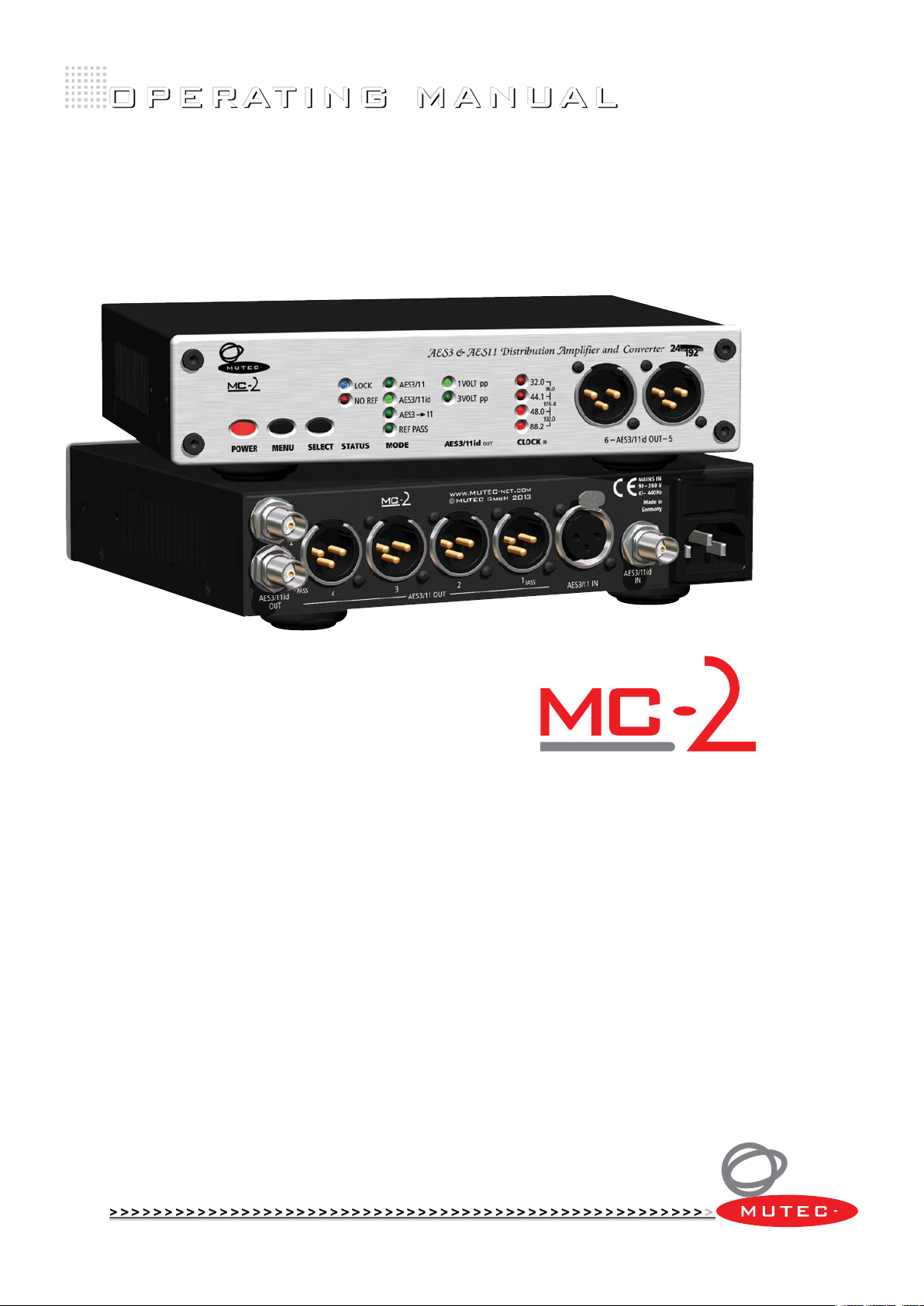
AES3 & AES11 Distribution Amplifier
and Converter
MUTEC part no. 8015-055
Professional A/V Technology
Germany
Page 2

Page 3
SAFETY INSTRUCTIONS
!
!
General instructions
To reduce the risk of fire or electrical shock, do not expose this appliance to rain or moisture, direct
sunlight or excessive heat from sources such as radiators or spotlights. No user serviceable parts are inside. Repair and maintenance must be carried out by qualified personnel authorized by MUTEC GmbH!
The unit has been designed for operation in a standard domestic environment. Do NOT expose the
unit and its accessories to rain, moisture, direct sunlight or excessive heat produced by such heat sources as radiators or spotlights! The free flow of air inside and around the unit must always be ensured.
CAUTION
RISK OF
ELECTRICAL SHOCK!
Initial operation
Prior to the init ial operation of the unit , the ap plianc e, its a ccessorie s and pac kaging m ust be
inspecte d for any si gns of ph ysical damag e that may h ave occurred du ring tra nsit . If the un it has
been da maged mechanicall y or if liquids have been spilled i nside t he encl osure , the app liance m ay
not be co nnec ted to the mains or m ust be disconnec ted fro m the mains imme diatel y! If the unit is
damag ed, please do N OT return it to MUTEC Gmb H, but no tify your deal er and th e shipp ing com pany immediat ely, oth erwise clai ms for damage or replac ement m ay not be granted .
If the device is left in a low-temperature environment for a long time and then is moved to a
room-temperature environment, condensation may occur on the inside and the exterior. To avoid
shortcircuits and flashovers, be sure to wait one or two hours before putting the device into operation.
Power supply
The device contains a self-adapting wide-range power supply supporting the majority of global standard line voltages within a range of 90…250 V, with no need for making adjustments. Make sure that
your line-voltage source provides a supply voltage within the specified range. In addition, make sure
that the device is properly grounded via the local electric installation.
Pleas e use th e enclo sed po wer cord ( see packaging) to connect th e unit to th e mains . Switch the
unit of f before you at tempt t o connect it to the mains . Connect th e power cord to the u nit, then
to a standard 3 -pin mains outlet. To dra w the power cord , never p ull on the c able but on the mains
plug!
The uni t must b e grounded during operation!
For information on the power-inlet wiring, refer to the »Wirin g of connectors« section in the
appendix. Disconnect the device from the mains when not using it for an extended period!
Declaration of Conformity
We herewith confirm that the product complies with the European
Commission’s standards on electromagnetic compatibility.
Interference emission: EN 50081-1, 1992
Resistance to interference: EN 50082-1, 1992
Presupposed as operation condition is that all clock outputs are
connected with high-quality and good shielded BNC 75 ohms cable.
This symbol, a flash of lightning inside a triangle, alerts
you to the presence of uninsulated dangerous voltage
inside the enclosure - voltage that may be sufficient to
constitute a risk of shock.
This symbol, an exclamation mark inside a triangle,
alerts you to important operating or safety instructions
in this manual.
WARRANTY REGULATIONS
§1 Warranty
MUTEC GmbH warrants the flawless performance of this product to the original buyer for a period of two (2) years from the date of purchase. If any failure occurs within
the specified warranty period that is caused by defects in material and/or workmanship, MUTEC GmbH shall either repair or replace the product free of charge within 90
days. The purchaser is not entitled to claim an inspection of the device free of charge during the warranty period. If the warranty claim proves to be justified, the product
will be returned freight prepaid by MUTEC GmbH within Germany. Outside Germany, the product will be returned with the additional international freight charges payable
by the customer. Warranty claims other than those indicated above are expressly excluded.
§2 Warranty transferability
This warranty is extended exclusively to the original buyer who bought the product from a MUTEC GmbH specialized dealer or distributor, and is not transferable to anyone
who may subsequently purchase this product. No other person (retail dealer, distributor, etc.) shall be entitled to give any warranty promise on behalf of MUTEC GmbH.
§3 Waranty regulations
The return of the completed registration card, or online registration on one of the websites specified below, is a condition of warranty. Failing to register the device before
returning it for repair will void the extended warranty.
The serial number on the returned device must match the one stated on the registration card or entered during online registration. Otherwise, the device will be
returned to the sender at the sender’s expense.
Any returned device must be accompanied by a detailed error description and a copy of the original sales receipt issued by a MUTEC dealer or distributor.
The device must be returned free of shipping expenses and in the original package, if possible; otherwise, the sender has to provide comparably protective packaging.
The sender is fully responsible for any damage or loss of the product when shipping it to MUTEC GmbH.
§4 Limitation of warrant y
Damages caused by the follow ing condition s are not covered b y this war ranty:
Damages caused by every kind of norm al wear an d tear (e.g. displays, L EDs, potentiometers , fader s, switche s, buttons, conn ecti ng elem ents , print ed labe ls, co ver
glasses, cover prints, and similar parts).
Functional failure of t he prod uct caused b y improper ins tallation (pleas e observe CM OS comp onent s handling ins truc tions!), negle ct or misuse of
the pro duct , e.g. fa ilure to o perate the unit i n compliance wi th the in stru ctions given in the us er or servic e manual s.
Damage caused by any form of ex ternal m echan ical im pact o r modif icati on.
Damage caused by the user’s f ailure to connect and operate t he unit in compli ance with loca l safet y regu lation s.
Damage caused by forc e majeur e (fire , explo sion, flood , lightning, war, vandalism, etc.).
Consequential damages or d efec ts in produc ts fro m other manufac turers as well as any costs re sulting from a loss of pr oduc tion.
Repair s carr ied out b y pers onnel w hich is n ot authorized f rom MUT EC GmbH w ill void the warranty. Adaptations and modifications to the device made with regard to
national, technical, or safety regulations in a country or of the customer do not constitute a warranty claim and should be set with MUTEC GmbH in advance.
§5 Repairs
To obtain warranty service, the buyer must call or write to MUTEC GmbH before returning the unit. All inquiries must be accompanied by a description of the problem and
the original buyer’s invoice. Devices shipped to MUTEC GmbH for repair without prior notice will be returned to the sender at the sender’s expense. In case of a functional
failure please contact:
MUTEC Gesellschaft fuer Systementwicklung und Komponentenvertrieb mbH
Siekeweg 6/8 • 123 09 Berlin • Germany • Fo n 030 -7468 80- 0 • Fax 030-746 880-9 9 • tecsuppor t@mutec-net.com • www.mutec-net.com
MUTEC GmbH assumes no liability for any incorrect information given in this manual. Please note that
all software/hardware product names are registered trademarks of their respective owners. No part of
this manual may be reproduced, copied or converted to a machine-readable form or electronical media
without a written permission of MUTEC GmbH. We reserve the right to change or improve our products
without notice. © MUTEC GmbH 2005-2014
Page 4

Page 5

CONTENT
INTRODUCTION
About this Manual . . . . . . . . . . . . . . . . . . . . . . . 7
General Function Description . . . . . . . . . . . . . . . . . 7
Features . . . . . . . . . . . . . . . . . . . . . . . . . . . . . 7
Applications . . . . . . . . . . . . . . . . . . . . . . . . . . . 8
Peripheral MUTEC Products . . . . . . . . . . . . . . . . . . 8
CONTROL ELEMENTS
MC-2 Front Panel . . . . . . . . . . . . . . . . . . . . . . . . 9
MC-2 Rear Panel . . . . . . . . . . . . . . . . . . . . . . . . 9
INSTALLATION
Content of the Box . . . . . . . . . . . . . . . . . . . . . . . 11
Placing the device . . . . . . . . . . . . . . . . . . . . . . . 11
Wiring the AES/EBU and AES/EBU ID Interfaces . . . . . . . 11
OPERATION
Selecting Function Areas and setting Functions . . . . . . . 13
Steps of Operation . . . . . . . . . . . . . . . . . . . . . . . 13
MODE Function Area . . . . . . . . . . . . . . . . . . . . . 14
AES/EBU . . . . . . . . . . . . . . . . . . . . . . . . . . . . . 14
AES/EBU + AES 3 → 11 . . . . . . . . . . . . . . . . . . . . . 14
AES/EBU + AES 3 → 11 + REF PASS . . . . . . . . . . . . . . . 14
AES/EBU ID . . . . . . . . . . . . . . . . . . . . . . . . . . . 14
AES/EBU ID + AES 3 → 11 . . . . . . . . . . . . . . . . . . . . 14
AES/EBU ID + AES 3 → 11 + REF PASS . . . . . . . . . . . . . 14
AES/EBU ID
STATUS Status Area . . . . . . . . . . . . . . . . . . . . . . 15
LOCK . . . . . . . . . . . . . . . . . . . . . . . . . . . . . . 15
NO REF . . . . . . . . . . . . . . . . . . . . . . . . . . . . . 15
CLOCK
OUT
Function Area . . . . . . . . . . . . . . . . . 14
IN
Status Area . . . . . . . . . . . . . . . . . . . . . . 15
APPENDIX
Pin Assignment of the Connectors . . . . . . . . . . . . . . 17
Connecting the AES/EBU ID Input to Ground . . . . . . . . . 18
Switching-off the Termination of the AES/EBU ID Input . . . 18
Technical Data . . . . . . . . . . . . . . . . . . . . . . . . . 19
Page 6

Page 7

BEDIENELEMENTE
!
!
BEDIENELEMENTE
BEDIENELEMENTE
\
>>>>>>>>>>>>>>>>>>>>>>>>>>>>>>>>>>>>>>>>>>>>>>>>>>>>>>>>>>>>>>>>>>>>
INTRODUCTION
Thank you very much for purchasing MC-2, AES/EBU Signal Distribution
Amplifier and Format Converter, from MUTEC!
About this Manual
The structure of this manual refers to the normal process of installing
MC-2 in a standard audio studio environment. Thus the chapters are
ergonomically sorted to provide a fast set-up. Before first power-on we
recommend to read the chapters INTRODUCTION and BRIEF INSTRUCTIONS
to get to know the general functionality of MC-2 and to reach a fast system
integration.
The chapter OPERATION describes individual functions which enable the
adaption of MC-2 to every studio environment. The chapters APPLICATION
EXAMPLE and APPENDIX include descriptions of favorable studio set-ups as
well as all technical information.
If there are any uncertainties when operating the units which can not be
cleared up by the content of this manual, please feel free to contact your
local dealer or MUTEC directly. All contact details are included in chapter
WARRANTY REGULATIONS located at the beginning of the manual.
The grey boxes contain supplementary
information for the corresponding sections
in the text columns. The content of the
individual box refers to the description in
the text column beside the box.
Boxes which contain a triangle
with an exclamation mark should
be read carefully! These include
additional information which are of major
importance for the functional descriptions in
the text column.
General Function Description
MC-2 is a high-performance digital audio and reference sync signal distribution amplifier and format converter for AES/EBU and AES/EBU ID signals.
MC-2 comes basically as an AES/EBU distribution amplifier. Additonally
AES/EBU ID interfaces are available as input and outputs. Using latest PLL
and conversion techniques, MC-2 processes reference signals aligned to
AES 3 / AES11 and AES 3 ID including all clock rates between 32 kHz and
192 kHz. Each interface standard offers one input whereas AES/EBU can be
distributed to 6 outputs and AES/EBU ID to 2 outputs.
Various operation modes enable the use of MC-2 in a wide range of applications. An input reference signal will be distributed to all outputs simultaneously. In this process, an electrical conversion between the AES/EBU and
the AES/EBU ID interfaces will be done automatically.
A supplied AES 3 signal can be format converted to AES 11 in realtime
and distributed through all outputs. If the original AES 3 signal is needed
furthermore, the first output of the according interface standard can be
switched to pass the original signal separately.
The voltage of the outputs of the AES/EBU ID interface can be switched
from standard 1 V to 3 V to enable longer cable runs.
All functions can be set convenient from the front panel with help of a
simple user interface. The device is shipped in a rugged aluminium housing
and meets CE, UL and FCC, part 15, specifications.
Features
AES/EBU and AES/EBU ID interfaces in one box.
Supports all audio-related clock rates between 32 kHz and 192 kHz.
Signal improvement by low-jitter PLLs.
Conversion from AES 3 to AES 11.
Detects and monitors all studio sampling rates between
32 kHz and 192 kHz.
Reference pass functionality.
Input lock detection.
All interfaces meet the specifications of the according AES and
AES ID standards.
Simple user interface.
Built-in international power supply.
Register your MUTEC Product
for Warranty and Support!
We ask you to be so kind to register
your MUTEC product through our website
immediately after purchasing. This ensures
full warranty services over a period of two
years after purchasing the product. Moreover, for all registered products we offer to
our customers technical support. We also
will inform you about product updates and
new products which may of interest for you
(on voluntary base, of course).
Please regsiter your product at:
www.MUTEC-net.de
>SERVICES, >MUTEC Product Registration
>>>>>>>>>>>>>>>>>>>>>>>>>>>>>>>>>>>>>>>>>>>>>>>>>>>>>>>>>>>>>>>>>>>>
88
7
Page 8

INTRODUCTION
INTRODUCTION
INTRODUCTION
\\\\\\\\\\\\
>>>>>>>>>>>>>>>>>>>>>>>>>>>>>>>>>>>>>>>>>>>>>>>>>>>>>>>>>>>>>>>>>>>>
Applications
AES/EBU and AES/EBU ID reference signal distribution.
AES/EBU and AES/EBU ID digital audio signal distribution.
Reference signal and digital audio signal refreshing.
Signal conversion between AES/EBU and AES/EBU ID.
AES 3 to AES 11 conversion.
Clock rate indication of AES/EBU and AES/EBU ID signals.
Line extension for e.g. theater or broadcast installations.
Output expansion for e.g. MUTEC’s iCLOCK, iCLOCK dp, iD, iD dp,
MC-3 SMART CLOCK, MC-3.1 SMART CLOCK SD, MC-3.2 SMART CLOCK HD
and other clock generators.
Peripheral MUTEC Products
Reference Clocks and Master Clocks for Synchronization:
iCLOCK + iCLOCKdp
iCLOCK and iCLOCKdp are synchronizable, high-precision clock
generators which are designed to be the reference in digital audio and
video studios as well as broadcast and television stations. For further
details please visit:
www.iCLOCK-NET.de
MC-3
The MC-3 SMART CLOCK is an universal digital audio master clock
generator. The unit provides different high-stable and Ultra low-jitter
clock signals for synchronization of various digital audio devices.
MC-3.1
The MC-3.1 SMART CLOCK SD is an universal digital audio and SD video
sync master clock generator. The unit provides different high-stable
clock signals for simultaneous synchronization of digital audio and SD
video devices.
MC-3.2
The MC-3.2 SMART CLOCK HD is an universal digital audio and SD/HD
video sync master clock generator. The unit provides different highstable clock signals for simultaneous synchronization of digital audio
and SD/HD video devices.
Format and Sampling Rate Converters with internal Master Clock:
MC-4
The MC-4 is a high-performance digital audio multichannel format and
sampling rate converter for ADAT
MC-6
The MC-6 is a high-performance digital audio dual channel format converter for AES3, AES3id and S/P-DIF.
MC-8 + MC-8.1
The MC-8 and MC-8.1 are 8 channel, high-performance digital audio and
sampling rate converters for AES3 and AES3id.
Cables for Digital Audio:
MW-05/19
Set of two rack mounting angles to install one MC product frontally into
one unit of a 19” rack.
MW-03/19
Set of two rack mounting angles to install one MC product on the rear
side of a 19” rack.
MW-02/19
Mounting plate to install two MC products side by side into one unit of
a 19” rack.
TM
, AES3 and S/P-DIF
88
>>>>>>>>>>>>>>>>>>>>>>>>>>>>>>>>>>>>>>>>>>>>>>>>>>>>>>>>>>>>>>>>>>>>
8
Page 9

BEDIENELEMENTE
BEDIENELEMENTE
BEDIENELEMENTE
\
>>>>>>>>>>>>>>>>>>>>>>>>>>>>>>>>>>>>>>>>>>>>>>>>>>>>>>>>>>>>>>>>>>>>
CONTROL ELEMENTS
MC-2 Front Panel
MC-2 Front Panel
5321
6 7
4
1 POWER
This red LED lights up when the unit is switched on with the rear panel
POWER switch.
2 SELECT
The toggle switch selects one of the two functional areas available.
3 DATA
Use this toggle switch to select a function from a specific functional area.
4 STATUS
This area indicates the status of the internal low-jitter PLL.
5 MODE
This area enables the selection of the reference input as well as the needed
conversion mode.
6 AES/EBU ID
This function enables to select two different output voltages for the
AES/EBU ID outputs.
7 CLOCK
This status area indicates the clock rate of the current incoming reference
signal.
8 AES/EBU OUT 5 + 6
These are AES/EBU signal distribution outputs no. 5 + 6.
OUT
IN
8
MC-2 Rear Panel
Refer to the OPERATIONS chapter for more
information.
MC-2 Rear Panel
1 2 3 4 5
1 AES/EBU ID OUT 1 + 2
These outputs transmit digital AES/EBU ID blank frame reference or audio
signals in accordance with the specifications of the standards
AES 3 ID – 1995/2001. The output impedance is 75 Ω (BNC connector,
female).
2 AES/EBU OUT 1 – 4
These outputs transmit balanced digital AES/EBU blank frame reference or
audio signals in accordance with the specifications of the standards
AES 3 – 1992/2003 and AES 11 – 1997/2003. The output impedance is 110 Ω
(XLR connectors, male).
3 AES/EBU IN
This input receives balanced digital AES/EBU blank frame reference or audio
signals in accordance with the specifications of the standards
>>>>>>>>>>>>>>>>>>>>>>>>>>>>>>>>>>>>>>>>>>>>>>>>>>>>>>>>>>>>>>>>>>>>
88
9
Page 10

CONTROL ELEMENTS
CONTROL ELEMENTS
CONTROL ELEMENTS
\\\\\\\\\\\\\
>>>>>>>>>>>>>>>>>>>>>>>>>>>>>>>>>>>>>>>>>>>>>>>>>>>>>>>>>>>>>>>>>>>>
AES 3 – 1992/2003 and AES 11 – 1997/2003. The input impedance is 110 Ω (XLR
connector, female).
4 AES/EBU ID IN
The AES/EBU ID input terminal is standardly
isolated from ground to avoid interference
from the connected clock line. If this does
not comply with the electrical studio purposes, the ground connections can be linked
permanently by setting jumpers on the
mainboard. Refer to the »Connecting the
AES/EBU ID Input to Ground« section in the
appendix for a short instruction.
For detailed specifications on all terminals,
refer to the PIN ASSIGNMENT OF THE
CONNECTORS and TECHNICAL DATA sections
in the appendix.
This input receives balanced digital AES/EBU blank frame reference or audio
signals in accordance with the specifications of the standards
AES 3 ID – 1995/2001. The input impedance is 75 Ω (BNC connector, female)
and can be switched off internally for chaining devices, see the »Switching-off the Termination of the AES/EBU ID Input« section in the appendix.
5 MAINS IN, Power Switch + Power Inlet
This is the main switch for switching the device on and off. Be sure to
make all connections (especially the supplied power cable) properly before
turning on the switch. Heed the SAFETY INSTRUCTIONS at the beginning of
this manual.
Connect the supplied power cable here. Make sure that the power switch
is turned off before connecting the power cable to this inlet and to the
power outlet. Line voltages within the range of 90…260 V with a frequency
of 50 or 60 Hz can be applied. The internal power supply will automatically
make all necessary adjustments.
88
>>>>>>>>>>>>>>>>>>>>>>>>>>>>>>>>>>>>>>>>>>>>>>>>>>>>>>>>>>>>>>>>>>>>
10
Page 11

BEDIENELEMENTE
!
!
!
!
BEDIENELEMENTE
BEDIENELEMENTE
\
>>>>>>>>>>>>>>>>>>>>>>>>>>>>>>>>>>>>>>>>>>>>>>>>>>>>>>>>>>>>>>>>>>>>
INSTALLATION
Content of the Box
The unit was packed carefully. Nevertheless we recommend to check the
content directly after opening the package:
1 x MC-2
1 x Power cable
4 x Rubber feet
1 x Manual
Placing the Device
The unit should be set up as closely as possible to the devices to which it
will be connected, so as to avoid excessive cable lengths. Use the 4 rubber
feets enclosed with the appliance and stick them symmetrically on the
bottom side of the unit to protect the enclosure and supporting surface
from being damaged.
The device can be mounted into a standard 19“ rack and will require 1 unit.
In this case, the rubber feet cannot be attached. Install the device so that
one unit of rack space is left free both above and below the device to allow
for sufficient ventilation! The mounting depth including the terminals is
160 mm/6.7“. Another 60 mm/2.4“ should be added for the required cables.
Additional slide-in rails on the rack inside are recommended for safe installation. This will also avoid long-term mechanical deformation of the housing.
If there are any damages please refer to
SAFETY INSTRUCTIONS, Initial Operation,
and WARRANTY REGULATIONS.
should be read carefully.
produced by radiators, heaters, or spot
lights! Sufficient air circulation in the
environment of the device must be ensured!
The condition of the packaging
material and the device should
be checked carefully additionally.
Before installing the unit the section
SAFETY INSTRUCTIONS located
at the beginning of this manual
Never expose the device and
accessories to rain, moisture,
direct sunlight, or excessive heat
Wiring the AES/EBU and AES/EBU ID interfaces
Connect the AES/EBU interfaces with the help of balanced electrical
cables equipped with XLR connectors on both ends. The specifications
stipulate a specific cable resistance of 110 Ω (ask your retailer for a confir-
mation of this value when purchasing the cables).
Connect the AES/EBU ID interfaces with the help of unbalanced electrical
cables equipped with BNC connectors on both ends. The specifications stipulate a specific cable resistance of 75 Ω (ask your retailer for a confirmation
of this value when purchasing the cables).
Especially when working with high
AES/EBU clock rates well shielded
clock lines are imperative to avoid
increased radiation! Standard cables are normally useable for clock rates up to 50.0kHz.
Special shielded cable material should be
used for transfer of higher clock rates.
Since some manufacturers offer optimized
cables for the transmission of AES/EBU and
AES/EBU ID signals, it will be a good idea to
ask your retailer for specific cables.
>>>>>>>>>>>>>>>>>>>>>>>>>>>>>>>>>>>>>>>>>>>>>>>>>>>>>>>>>>>>>>>>>>>>
88
11
Page 12

12
Page 13

BEDIENELEMENTE
!
!
BEDIENELEMENTE
BEDIENELEMENTE
\
>>>>>>>>>>>>>>>>>>>>>>>>>>>>>>>>>>>>>>>>>>>>>>>>>>>>>>>>>>>>>>>>>>>>
OPERATION
Selecting Function Areas and setting Functions
The device is fully operated using the two toggle switches at the front
panel.
1 Switching the SELECT switch selects between different basic
function areas.
2 Switching the DATA switch selects between the individual
functions within one function area.
powering-up!
We also recommend reading the CONTROLS
AND TERMINALS chapter for information on
how to connect MC-2!
For safety reasons, be sure to read
the SAFETY INSTRUCTIONS and
INSTALLATION chapters before first
1. SELECT
selects individual
function areas.
SELECT + DATA operation
Function Areas + Status Areas
2. DATA
selects individual
functions within
one function
area.
Function
Areas
Status Areas
Functions
Functions
Steps of Operation
1 First press on SELECT or DATA switch enables the last selected function
within the last selected function area. The corresponding LED is
beginning to flash.
2 Every press on DATA switch will select a new function. The LED of every
selected function will flash accordingly and the corresponding function is
available at once.
3 When the needed function is selected, do not press the switches again!
After a period of approx. 4 seconds the LED in front of the selected
function will stop flashing.
The STATUS area is not accessible by using the SELECT and DATA switches,
because it only informs about different conditions of incoming digital
audio signals.
>>>>>>>>>>>>>>>>>>>>>>>>>>>>>>>>>>>>>>>>>>>>>>>>>>>>>>>>>>>>>>>>>>>>
All user-specific function settings
are available furthermore when
power is restored.
88
13
Page 14

OPERATION
OPERATION
OPERATION
\\\\\\\\\\\\
>>>>>>>>>>>>>>>>>>>>>>>>>>>>>>>>>>>>>>>>>>>>>>>>>>>>>>>>>>>>>>>>>>>>
MODE Function Area
The function area MODE includes six different operation modes for signal
distribution which are accessible by repeatedly pressing the DATA switch.
One or more LEDs will light for the corresponding mode, respectively for
combinations of modes. During the signal distribution process, the status
of the internal PLL circuit will be displayed in the status area STATUS.
Furthermore the clock rate of the incoming reference signal will be
analyzed and reported in the status area CLOCK IN. During all distribution
and conversion processes, the status bit settings of the incoming signal will
be not affected.
The factory default setting is AES/EBU.
AES/EBU
This function distributes an incoming AES/EBU reference signal alinged
to AES 3 or AES 11 directly to all AES/EBU and AES/EBU ID outputs
simultaneously. The internal PLL circuit is stabilizing and de-jittering, the
output driver stages are refreshing the incoming signal. The output level of
the AES/EBU ID outputs can be selected in function area AES/EBU ID
AES/EBU + AES 3 → 11
This function combination distributes an incoming AES/EBU reference
signal as described above. Additionally this function converts an digital
audio signal (AES 3) which is supplied at the AES/EBU input into an digital
reference sync signal (aligned to AES 11). A real format conversion is carried
out during this process!
OUT.
Example
In a studio environment the only sync reference is a digital audio signal. This signal
should be available for a DA converter. But
at the same time sync reference signals are
needed for devices which should to be synchronized to e.g. the digital mixing desk.
In this case the »AES/EBU + AES 3 → 11 + REF
PASS« function helps to make the digital
audio signal available for the DA converter,
while having a sync reference based on the
phase relationship of the digital audio signal
available for synchronization of the other
devices to the mixing desk.
AES 3
IN
AES 3
OUT
3 x AES 11
OUT
2 x AES 11 ID
OUT
AES/EBU + AES 3 → 11 + REF PASS
This combination of three functions distributes and converts an incoming
AES/EBU reference signal as described under „AES/EBU“ and „AES/EBU
AES 3 → 11“. Additionally the system outputs the original incoming signal
at AES/EBU output no. 1 (marked as „1/
carrying the converted AES 11 sync signal.
AES/EBU ID
This function distributes an incoming AES/EBU ID reference signal alinged
to AES 3 ID directly to all AES/EBU ID and AES/EBU outputs simultaneously.
The internal PLL circuit is stabilizing and de-jittering, the output driver
stages are refreshing the incoming signal. The output level of the AES/EBU
ID outputs can be selected in function area AES/EBU ID
AES/EBU ID + AES 3 → 11
This function combination distributes an incoming AES/EBU ID reference
signal as described above. Additionally this function converts an digital
audio signal (AES 3) which is supplied at the AES/EBU ID input into an
digital reference sync signal (aligned to AES 11). A real format conversion is
carried out during this process!
AES/EBU ID + AES 3 → 11 + REF PASS
This combination of three functions distributes and converts an incoming
AES/EBU ID reference signal as described under „AES/EBU ID“ and „AES/EBU
ID + AES 3 → 11“. Additionally the system outputs the original incoming
signal at AES/EBU ID output no. 1 (marked as „1/
outputs are carrying the converted AES 11 sync signal.
PASS“) while all other outputs are
OUT.
PASS“) while all other
+
2 x AES 11
AES 3: Digital Audio Signal
AES 11: Sync Reference Signal (converted out of AES 3)
»AES/EBU + AES 3 → 11 + REF PASS« Function
88
>>>>>>>>>>>>>>>>>>>>>>>>>>>>>>>>>>>>>>>>>>>>>>>>>>>>>>>>>>>>>>>>>>>>
14
OUT
Page 15

OPERATION
OPERATION
OPERATION
\\\\\\\\\\\\
>>>>>>>>>>>>>>>>>>>>>>>>>>>>>>>>>>>>>>>>>>>>>>>>>>>>>>>>>>>>>>>>>>>>
AES/EBU ID OUT Function Area
This function area enables to change the output level of the AES/EBU ID
outputs from 1V peak – peak, which is the standard aligned to AES 3 ID, to
3V peak – peak. The level change can be activated in all operation modes of
MC-2.
The factory default setting is 1 VOLT
STATUS Status Area
This area displays the status of the internal low-jitter PLL circuit.
LOCK
When the LOCK LED lights, the PLL circuit is locked to the external digital
audio or sync reference signal. This signal will be processed and transfered
like described previously to all corresponding outputs. The four LEDs of the
CLOCK IN status area will display the clock rate of the reference signal.
NO REF
When the NO REF LED lights, the PLL circuit is not locked to an external
digital audio or sync reference signal. This can be caused by a missing
or absent reference as well as by an extremely unstable or interrupted
reference signal. All outputs are muted, no LED of the CLOCK IN status area
will light.
PP.
Example
This function can be useful if AES 3 ID signals
need to be transfered about very long distances to ensure to have enough signal level
for the input circuits of the receiving devices
available.
CLOCK IN Status Area
This area displays the clock rate of the incoming digital audio or sync
reference signal. The following rates are supported and will be analyzed
32.0 kHz 44.1 kHz 48.0 kHz 88.2 kHz 96.0 kHz
176.4 kHz 192.0 kHz
These indications are only available if the internal PLL circuit is locked stably
to the external reference signal and the corresponding blue LOCK-LED
lights permanently.
88
>>>>>>>>>>>>>>>>>>>>>>>>>>>>>>>>>>>>>>>>>>>>>>>>>>>>>>>>>>>>>>>>>>>>
15
Page 16

16
Page 17

BEDIENELEMENTE
BEDIENELEMENTE
BEDIENELEMENTE
\
>>>>>>>>>>>>>>>>>>>>>>>>>>>>>>>>>>>>>>>>>>>>>>>>>>>>>>>>>>>>>>>>>>>>
APPENDIX
Pin Assignment of the Connectors
Mains
3
2
1
1 Neutral (blue; USA: white)
2 Protective earth (green/yellow; USA: green)
3 Live, phase (brown; USA: black)
AES/EBU XLR Output AES/EBU XLR Input
1
2
3
1 Ground
2 a conductor (hot / +)
3 b conductor (cold / -)
AES/EBU ID BNC Input / Output
1
2
1 Signal
2 Ground
2
1
3
1 Ground
2 a conductor (hot / +)
3 b conductor (cold / -)
>>>>>>>>>>>>>>>>>>>>>>>>>>>>>>>>>>>>>>>>>>>>>>>>>>>>>>>>>>>>>>>>>>>>
88
17
Page 18

APPENDIX
When moving the jumpers of the
sockets JP 3 and JP 4 to switch-off
the AES/EBU ID input termination,
the input hast to be connected to ground
simultaneously!
!
APPENDIX
APPENDIX
\\\\\\\\\\\\
>>>>>>>>>>>>>>>>>>>>>>>>>>>>>>>>>>>>>>>>>>>>>>>>>>>>>>>>>>>>>>>>>>>>
Connecting the AES/EBU ID Input to Ground
AES/EBU ID
INPUT
AES/EBU
INPUT
CAUTION! Disconnect the unit from the mains before opening!
Remount the aluminium cover thoroughly before you attempt to operate
the unit!
When MC-2 is shipped, the BNC-based
AES/EBU ID input is isolated from ground.
JP 2
Jumper:
Status connector JP 3
Ground connector JP 2
Termination connector JP 4
JP 2JP 2
Setting the jumper one pin forward in direction
to the housing’s leftside (viewed from the front
panel) will connect the BNC input connector to
ground.
This setting is also necessary when switching-off
the termination (see below)!
Switching-off the Termination of the AES/EBU ID Input
CAUTION! Disconnect the unit from the mains before opening!
Remount the aluminium cover thoroughly before you attempt to operate
the unit!
When MC-2 is shipped, the BNC-based
AES/EBU ID input is terminated internally with
75 Ω. Therefore, two jumpers are put on two
3-pin sockets, JP 4 for termination and JP 3 for
status.
Moving the jumpers of each socket in the
opposite position will switch of the 75 Ω termi-nation of the AES/EBU ID input.
JP 2
JP 4
JP 4
JP 3
JP 3
wrong right
88
>>>>>>>>>>>>>>>>>>>>>>>>>>>>>>>>>>>>>>>>>>>>>>>>>>>>>>>>>>>>>>>>>>>>
Page 19

APPENDIX
APPENDIX
APPENDIX
\\\\\\\\\\\\
>>>>>>>>>>>>>>>>>>>>>>>>>>>>>>>>>>>>>>>>>>>>>>>>>>>>>>>>>>>>>>>>>>>>
Technical Data
AES/EBU INPUT
Interface 1 x XLR female, transformer balanced, input impedance 110 Ω, 200 mV – 7.0 V
Format AES3 – 1992/2003 and AES11 – 1997/2003
Resolution 16 – 24 bits
Lock range Every digital audio clock rate from 32.0kHz to 192.0kHz
AES/EBUid INPUT
Interface 1 x BNC female, unbalanced, input impedance 75 Ω, 200 mV – 7.0 V
Format AES3id – 1995/2001
Resolution 16 – 24 bits
Lock range Every digital audio clock rate from 32.0 kHz to 192.0 kHz
AES/EBU OUTPUTs 1 – 6
Interface 6 x XLR male, transformer balanced, 3.5 Vpp @ 110 Ω, output impedance 110 Ω, buffered
Format AES3 – 1992/2003 and AES11 – 1997/2003
Resolution 16 – 24 bits
Transmitted audio clock rates Every digital audio clock rate from 32.0kHz to 192.0kHz
AES/EBUid OUTPUTs 1 + 2
Interface 2 x BNC female, unbalanced, 1.0 / 3.0 Vpp @ 75 Ω, output impedance 75 Ω, buffered
Format AES3id – 1995/2001
Resolution 16 – 24 bits
Transmitted audio clock rates Every digital audio clock rate from 32.0kHz to 192.0kHz
SIGNAL PROCESSING
Signal processes
Clock rate analyzing
POWER SUPPLY
Type Internal, switching power supply
Input voltage 90 V – 260 V (automatic adjustment), 47 Hz – 440 Hz
Power consumption max. 10 W
SYSTEM UNIT COVER
Cover size / material / color 196 x 42 x 156mm without connectors (W x H x D), aluminium sheet 1mm, black
Front panel size / material 198 x 44 x 2mm (W x H x D), aluminium
Weight ~ 1210g
AES/EBU to AES/EBUid + AES/EBUid to AES/EBU electrical conversion
Signal stabilization and refreshing by low-jitter PLL
Automatic clock rate detection of the incoming reference signal between
32.0 kHz and 192.0 kHz in all operation modes.
88
>>>>>>>>>>>>>>>>>>>>>>>>>>>>>>>>>>>>>>>>>>>>>>>>>>>>>>>>>>>>>>>>>>>>
19
Page 20

>>>>>>>>>>>>>>>>>>>>>>>>>>>>>>>>>>>>>>>>>>>>>>>>>>>>>>>>>>>>>
ALL SOFTWARE AND HARDWARE PRODUCT NAMES ARE REGISTERED TRADEMARKS OF THEIR RESPECTIVE OWNERS.
WE RESERVE THE RIGHT TO CHANGE TECHNICAL DETAILS WITHOUT PRIOR NOTICE.©MUTEC GmbH 2002•7045-014
FON 0049-(0)30-7468 80-0
FAX 0049-(0)30-74 68 80-99
WWW.MUTEC-NET.DE
Professional A/V Technology
Germany
 Loading...