

Page 1
REDUNDANT MULTIPLE CLOCK SYNTHESIZER
AND VIDEO REFERENCE GENERATOR
VERSION 2.22
Page 2

Page 3
SAFETY INSTRUCTIONS
!
!
General instructions
To reduce the risk of fire or electrical shock, do not expose this appliance to rain or moisture, direct
sunlight or excessive heat from sources such as radiators or spotlights. No user serviceable parts are inside. Repair and maintenance must be carried out by qualified personnel authorized by MUTEC GmbH!
The unit has been designed for operation in a standard domestic environment. Do NOT expose the unit
and its accessories to rain, moisture, direct sunlight or excessive heat produced by such heat sources as
radiators or spotlights! The free flow of air inside and around the unit must always be ensured.
CAUTION
RISK OF
ELECTRICAL SHOCK!
Initial operation
Prior to the initi al operation of the u nit, the applian ce, its a ccess ories and packag ing must be
inspected f or any signs of physical damage that may have occurred dur ing transit. If t he unit ha s
been da maged mechanically or if liquids h ave been s pilled i nside th e enclosure, the applian ce may
not be co nnect ed to the mains or mus t be disconnec ted fro m the mains immedi ately! If the unit is
damag ed, please do NOT r eturn it t o MUTEC GmbH, but n otify your dealer and the s hipping c ompany immediately, otherwise claims fo r damage o r replac ement ma y not be granted.
If the device is left in a low-temperature environment for a long time and then is moved to a roomtemperature environment, condensation may occur on the inside and the exterior. To avoid shortcircuits and flashovers, be sure to wait one or two hours before putting the device into operation.
Power supply
The device contains a self-adapting wide-range power supply supporting the majority of global standard line voltages within a range of 90…250 V, with no need for making adjustments. Make sure that
your line-voltage source provides a supply voltage within the specified range. In addition, make sure
that the device is properly grounded via the local electric installation.
Pleas e use the e nclosed power cord (see p ackaging) to connect the u nit to the mains. Sw itch the
unit of f before you atte mpt to con nect it to the main s. Connect the p ower cor d to the unit, then
to a standard 3-pin mains outle t. To draw the p ower cor d, never p ull on the c able but o n the main s
plug!
The uni t must be g rounde d during operation!
For information on the power-inlet wiring, refer to the »Wirin g of conne ctors« section in the
appendix. Disconnect the device from the mains when not using it for an extended period!
Declaration of Conformity
We herewith confirm that the product complies with the European
Commission’s standards on electromagnetic compatibility.
Interference emission: EN 55103-1:1996
Resistance to interference: EN 55103-2:1996
Presupposed as operation condition is that all clock outputs are connected with high-quality and good shielded BNC 75 ohms cable.
This symbol, a flash of lightning inside a triangle, alerts
you to the presence of uninsulated dangerous voltage
inside the enclosure - voltage that may be sufficient to
constitute a risk of shock.
This symbol, an exclamation mark inside a triangle,
alerts you to important operating or safety instructions
in this manual.
WARRANTY REGULATIONS
§1 Warranty
MUTEC GmbH warrants the flawless performance of this product to the original buyer for a period of two (2) years from the date of purchase. If any failure occurs within
the specified warranty period that is caused by defects in material and/or workmanship, MUTEC GmbH shall either repair or replace the product free of charge within 90
days. The purchaser is not entitled to claim an inspection of the device free of charge during the warranty period. If the warranty claim proves to be justified, the product
will be returned freight prepaid by MUTEC GmbH within Germany. Outside Germany, the product will be returned with the additional international freight charges payable
by the customer. Warranty claims other than those indicated above are expressly excluded.
§2 Warranty transferability
This warranty is extended exclusively to the original buyer who bought the product from a MUTEC GmbH specialized dealer or distributor, and is not transferable to anyone
who may subsequently purchase this product. No other person (retail dealer, distributor, etc.) shall be entitled to give any warranty promise on behalf of MUTEC GmbH.
§3 Waranty regulations
The return of the completed registration card, or online registration on one of the websites specified below, is a condition of warranty. Failing to register the device before
returning it for repair will void the extended warranty.
The serial number on the returned device must match the one stated on the registration card or entered during online registration. Otherwise, the device will be
returned to the sender at the sender’s expense.
Any returned device must be accompanied by a detailed error description and a copy of the original sales receipt issued by a MUTEC dealer or distributor.
The device must be returned free of shipping expenses and in the original package, if possible; otherwise, the sender has to provide comparably protective packaging.
The sender is fully responsible for any damage or loss of the product when shipping it to MUTEC GmbH.
§4 Limitation of warrant y
Damages caus ed by the following c onditions are not covered b y this warranty:
Damages caus ed by ever y kind of normal wea r and tear (e.g. displays, LEDs, po tentio meter s, faders, switches, but tons, connec ting ele ments , printe d label s, cover
glasses, cover prints, and similar parts).
Functional fai lure of the p roduc t caused by improper ins tallation (pl ease ob serve CMOS component s handling instructions!), neg lect or misuse of
the pro duct , e.g. failure to operate the un it in compliance wi th the ins truc tions gi ven in the u ser or servic e manuals.
Damage caused by any form o f exter nal mech anical i mpact o r modifi cation.
Damage caused by the use r’s failure to conn ect and o perate t he unit in complian ce with lo cal safety reg ulation s.
Damage caused by force ma jeure (fi re, explosion , flood , lightni ng, war, vandalism , etc.).
Any consequential damages or de fect s in produ cts from other manufac turers and any arising costs f rom impa irment o r loss of p roduc tions or a ny other forms of ev ents.
Repair s carri ed out by person nel which is not authorized f rom MUTEC GmbH will void the warranty. Adaptations and modifications to the device made with regard to
national, technical, or safety regulations in a country or of the customer do not constitute a warranty claim and must be set with MUTEC GmbH in advance.
§5 Repairs
To obtain warranty service, the buyer must call or write to MUTEC GmbH before returning the unit. All inquiries must be accompanied by a description of the problem and
the original buyer’s invoice. Devices shipped to MUTEC GmbH for repair without prior notice will be returned to the sender at the sender’s expense. In case of a functional
failure please contact:
MUTEC Gesellschaft fuer Systementwicklung und Komponentenvertrieb mbH
Siekeweg 6/8 • 12309 Berlin • Germa ny • Fon 030 -746 880 -0 • Fax 0 30-74 6880-99 • Tecsupport@MUTEC-net.com • www.MUTEC-net.com
MUTEC GmbH assumes no liability for any incorrect information given in this manual. Please note that
all software/hardware product names are registered trademarks of their respective owners. No part of
this manual may be reproduced, copied or converted to a machine-readable form or electronical media
without a written permission of MUTEC GmbH. We reserve the right to change or improve our products
without notice. © MU TEC GmbH 200 4 – 2013
Page 4

Page 5

CONTENT
INTRODUCTION
About this Manual . . . . . . . . . . . . . . . . . . . . . . . 7
General Function Description . . . . . . . . . . . . . . . . . 7
Differences between Software V2.10 and V2.11 . . . . . . . 8
Features . . . . . . . . . . . . . . . . . . . . . . . . . . . . . 8
Applications . . . . . . . . . . . . . . . . . . . . . . . . . . . 8
Optional Products . . . . . . . . . . . . . . . . . . . . . . . 8
CONTROL ELEMENTS
iCLOCK Front Panel . . . . . . . . . . . . . . . . . . . . . . . 9
iCLOCK + iCLOCK dp Rear Panels . . . . . . . . . . . . . . . 9
INSTALLATION
Content of the Box . . . . . . . . . . . . . . . . . . . . . . . 11
Placing the Device . . . . . . . . . . . . . . . . . . . . . . . 11
Wiring the Word Clock and Video Interfaces . . . . . . . . . 11
Wiring the AES/EBU and S/PDIF Interfaces . . . . . . . . . . 12
GENERAL OPERATION
Menu Structure . . . . . . . . . . . . . . . . . . . . . . . . . 13
Selecting Menu Pages and setting Functions . . . . . . . . 14
MENUS AND FUNCTIONS
Main Menu Page . . . . . . . . . . . . . . . . . . . . . . . . 14
Selecting and activating Clock Sources . . . . . . . . . . . 16
Configuring the internal Video Reference Generator . . . . 18
Configuring the Word Clock Outputs . . . . . . . . . . . . . 20
Configuring the AES/EBU Outputs . . . . . . . . . . . . . . 21
Configuring the S/PDIF Outputs . . . . . . . . . . . . . . . . 23
Setting System Functions
Preset Management . . . . . . . . . . . . . . . . . . . . . . 29
(Pull Up/Pull Down, Varispeed, etc.)
. . 25
iCLOCK TECHNOLOGY
Functional Principle . . . . . . . . . . . . . . . . . . . . . . . 33
SoftReLock . . . . . . . . . . . . . . . . . . . . . . . . . . . 33
Sequence Synchronization . . . . . . . . . . . . . . . . . . . 34
Cycle Synchronization . . . . . . . . . . . . . . . . . . . . . 34
iCLOCK EXTENSIONS
iC-ALARM up to V2.10 . . . . . . . . . . . . . . . . . . . . . 35
iC-ALARM/GPI from V2.11 or higher . . . . . . . . . . . . . 36
General Function Description . . . . . . . . . . . . . . . . . 36
Features . . . . . . . . . . . . . . . . . . . . . . . . . . . . . 36
APPENDIX
Synchronizable HD tri-level Standards and Frame Rates . . . 37
Synchronizable and generatable Clock Rates . . . . . . . . . 37
Pin Assignment of the Connectors . . . . . . . . . . . . . . 38
Connecting the universal Clock Inputs to Ground . . . . . . 39
Switching-off the Termination of the universal Clock Inputs 39
Splitting-up the Video Outputs for dual
Video Generator Operation . . . . . . . . . . . . . . . . . . 39
Technical Data . . . . . . . . . . . . . . . . . . . . . . . . . 40
Page 6

Page 7

BEDIENELEMENTE
!
BEDIENELEMENTE
BEDIENELEMENTE
\
>>>>>>>>>>>>>>>>>>>>>>>>>>>>>>>>>>>>>>>>>>>>>>>>>>>>>>>>>>>>>>>>>>>>
INTRODUCTION
Thank you very much for purchasing iCLOCK or iCLOCK dp, Redundant
Multiple Clock Synthesizer & Video Reference Generator, from MUTEC!
About this Manual
The whole manual is related to both versions in general, iCLOCK and
iCLOCK dp. The individual differences are mentioned in the according
sections and chapters.
The structure of this manual refers to the normal process of installing
iCLOCK in a standard audio/video studio environment. Thus the chapters
are ergonomically sorted to provide a fast set-up. Before first power-on we
recommend to read the chapters INTRODUCTION and BRIEF INSTRUCTIONS
to get to know the general functionality of iCLOCK and to reach a fast
system integration.
The following chapters OPERATION and iCLOCK TECHNOLOGY describe
individual functions which enable the adaption of iCLOCK to every studio
environment. The chapters APPLICATION EXAMPLE and APPENDIX include
descriptions of favorable studio set-ups as well as all technical information.
If there are any uncertainties when operating the units which can not be
cleared up by the content of this manual, please feel free to contact your
local dealer or MUTEC directly. All contact details are included in chapter
WARRANTY REGULATIONS located at the beginning of the manual.
The grey boxes contain supplementary
information for the corresponding sections
in the text columns. The content of the
individual box refers to the description in
the text column beside the box.
Boxes which contain a triangle
with an exclamation mark should
be read carefully! These include
additional information which are of major
importance for the functional descriptions in
the text column.
General Function Description
iCLOCK is a synchronizable, high-precision clock generator which is
designed to be the reference in digital audio and video studios as well
as broadcast and television stations. Based on a totally new concept
of frequency generation, developed by MUTEC, the unit offers an
unchallanged flexibility for synchronization of different devices to one
house clock. On this occasion iCLOCK breaks traditional, unflexible forms
of chaining input and output signals and allows for the first time their
completely free combination and scaleability.
iCLOCK‘s philosophy is addressed to provide the highest possible failure
safety for all outgoing clock signals which is needed especially for
broadcast stations or centralized clock distribution systems. With regards
to this functionality up to 3 independent external references can be autodetected and locked in a user-defined sequence without any phase-jumps
or interruptions in the outgoing signals. This applies also to external
clock frequency changes, e.g. from 44.1kHz to 48.0kHz or reference clock
changes, e.g. from video to GPS or AES11. Even if all external references
are lost, iCLOCK synthesizes the outgoing clock signals based on the
last incoming frequency constantly. If the absent reference clock returns
the synthesizer will lock gradually again based on iCLOCK’s SoftReLock
functionality which ensures interruption-free adjustments of all outgoing
clock signals. In this case a continous clock supply for all connected devices
is guaranteed during any operation mode.
For todays audio/video productions a precision synchronisation of the used
audio and video equipment is imperative. To reach the highest value of
accuracy the involved clock signals need to be synchronized and converted
without any phase drift. Therefore iCLOCK offers a unique, automatically
working signal management which observes the phase relationships of all
input and output signals and takes care of adjustments aligned to
AES11-1997/2003 and EBU R83-1996.
Using DDS-coupled frequency generation and latest DSP-based filtering
technologies in combination with an extremely low-jitter clock basis of
< 10ps (RMS), iCLOCK eliminates the jitter of incoming reference signals
completely. This ensures highest possible jitter attenuation for all outgoing
clock signals. As a result the synchronization of connected devices is much
more reliable and the sound quality of every AD/DA converter will be
increased significantly.
Synchronizable references
HD tri-level syncs
SD bi-level syncs
Word Clock + Word Clock x 256 (so called
Super Clock for ProTools
DSD 64, DSD 128 + DXD
AES3 + AES11
AES3 id + AES11 id
S/P-DIF
GPS
Telecom
DCF77
MSF60
Internal SD video reference generator
Further references through option cards
or custom designed-programming
TM
systems)
Generatable references
SD bi-level as Black & Burst or
composite sync
Word Clock + Word Clock x 256 (so called
Super Clock for ProTools
DSD64, DSD128 + DXD
Film and video frame + field rates
AES11
S/P-DIF
GPS
Further clock signals through option cards
TM
systems)
>>>>>>>>>>>>>>>>>>>>>>>>>>>>>>>>>>>>>>>>>>>>>>>>>>>>>>>>>>>>>>>>>>>>
88
7
Page 8

INTRODUCTION
INTRODUCTION
INTRODUCTION
\\\\\\\\\\\\
>>>>>>>>>>>>>>>>>>>>>>>>>>>>>>>>>>>>>>>>>>>>>>>>>>>>>>>>>>>>>>>>>>>>
Differences between Software V2.10 and V2.11
Both versions include the preset management as new functionality, which
was inquired by several professonal MUTEC customers (see page 28).
Using software V2.10 or V2.11 depends on the alarm interface you have
already installed or you plan to install. Software V2.10 supports only the
older interface iC-ALARM (ordering no. 8005- 056), whereas software
V2.11 supports only the new iC-AL ARM/GPI (ordering no. 8005-066).
The iC-ALARM/GPI interface offers same basis functionality like the iCALARM, but the new iC-ALARM/GPI interface allows for switching over the
different presets via its GPIO function (see page 31, 32).
Features
Synchronizable digital audio clock synthesizer with integrated
SD bi-level (PAL / NTSC) + Word Clock + AES11 + S/PDIF sync generators.
Locks nearly 20 different HD tri-level standards and frame rates
Converts HD tri-level syncs into SD bi-level syncs
High-accurate reference generation with an accuracy of < 0.1ppm.
Lowest jitter clock base with < 10ps (RMS).
Redundant (fail-safe) operation.
DDS-based jitter elimination of incoming reference signals.
Synchronizable SD bi-level, AES11 and S/PDIF generators.
Synchronization and generation of 36 Word Clock rates.
Generation of different PAL and NTSC pilot tones.
Synchronization and generation of all AES3/-11 and S/PDIF clock rates
up to 192.0kHz.
DSD64, DSD128 + DXD clock rates standardly supported.
High-accurate GPS or Atomic Clock references, like 10.0MHz and others,
are synchronizable, distributable and generatable.
No limitation of input assignment at the universal inputs.
SoftReLock functionality for recurring reference signals.
CYCLESYNC functionality for automatically re-synchronization.
Drop out compensation of incoming reference signals.
Generation of multiple clock rates at the same time.
Free scalability of all output clock signals.
Automatic signal management aligned to AES11 and EBU R83.
Digital varispeed up to ± 20%.
Supports all pull up/pull down rates for film, audio and video transfers.
Follows external references up to ± 20% (reducible).
Programming of additional clock rates between 1.0Hz – 25.0MHz.
Programming of additional lock ranges between 1.0kHz – 30.0MHz.
Eeasy and convenient operation through large display.
Soft and hardware upgradeability and recalibratability.
Applications
Audio and HD/SD video synchronization
Jitter attenuation in clock signals
Centralized + redundant A/V clock distribution
Conversion between HD tri-level syncs, SD bi-level syncs, Word Clock,
DSD, DXD, AES3/-11, AES3-/11id, S/PDIF, GPS, Telecom, DCF77, MFS60
and optional standards
Synchronization, distribution and generation of high-accurate
GPS or Atomic Clock references
Failure securing in clock distribution systems
Film, video and audio transfers
Synchronization of pilot tone resolvers, timecode generators,
film projectors
Coupling of HD/SD based multi-format video systems
Optional Products
iCLOCK dp iCLOCK basis unit with two redundant power supplies
P/NVSG-02 Second, synchronizable SD bi-level video sync generator
iC-ALARM Relais-coupled alarm signal interface
iC-ALARM/GPI Relais-coupled alarm signal and GPIO interface
iC-WCO-4 4 x Word Clock output expansion
iC-PROG Programming of additional clock rates and lock ranges
iC-CAL0.1 Re-calibration of internal reference oscillator to < 0.1ppm
88
>>>>>>>>>>>>>>>>>>>>>>>>>>>>>>>>>>>>>>>>>>>>>>>>>>>>>>>>>>>>>>>>>>>>
8
Page 9
BEDIENELEMENTE
BEDIENELEMENTE
BEDIENELEMENTE
\
>>>>>>>>>>>>>>>>>>>>>>>>>>>>>>>>>>>>>>>>>>>>>>>>>>>>>>>>>>>>>>>>>>>>
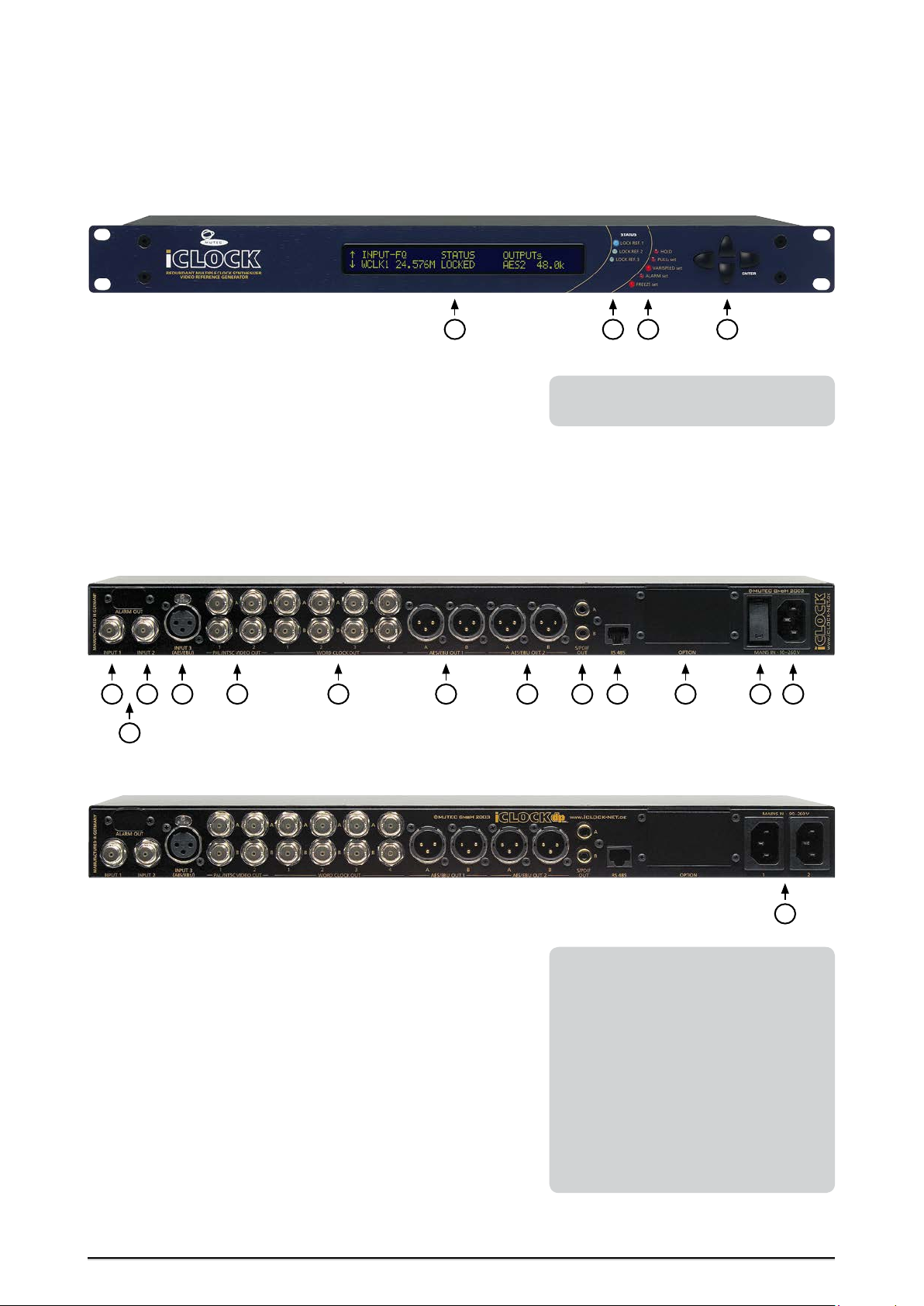
CONTROL ELEMENTS
iCLOCK + iCLOCK dp Front Panel
iCLOCK and iCLOCK dp front panels look equal
4321
1 DISPLAY
All parameter and function settings are controlled using the display and
the four cursor buttons.
2 + 3 STATUS Indicators
The three blue indicators show the lock status of the currently active clock
source. The five red indicators show important system statuses of iCLOCK.
4 CURSOR Buttons
All parameter and function settings are controlled using the four cursor
buttons and the display.
Refer to the OPERATIONS chapter for more
information.
iCLOCK Rear Panel
iCLOCK dp Rear Panel
1 + 2 INPUT1, INPUT2
These universal input terminals allow for applying various external clock
signals for synchronizing the internal clock synthesizer. All clock formats
supported by the system can be received at any of these inputs. These two
inputs and INPUT 3 can be synchronized by the synthesizer in a freely configurable sequence. The impedance of each input is 75 Ω and can be switched
off internally for chaining devices, see the »Switching-off the Termination
of the universal Clock Inputs« section in the appendix.
3 ALARM OUT
The iC-ALARM output is optionally available (item no. 8005-065). Refer to
the EXTENSIONS chapter for a short overview.
4 INPUT3 (AES/EBU)
A balanced digital AES/EBU signal can be applied to this input for synchronizing the internal clock synthesizer. The signal must comply with
AES3 – 1992 (R1997) or AES11 – 1997.
81 234 5 6 7 9 10 11 12 13
14
Both input terminals are isolated from
ground to avoid interference from the
connected clock line. This applies to all clock
references except video! Is a video signal
selected as reference the corresponding
input will be connected to ground automatically.
If this does not comply with the electrical
studio purposes, the ground connections of
both inputs could be linked permanently by
setting jumpers on the mainboard. Refer to
the »Connecting the universal Clock Inputs
to Ground« section in the appendix for a
short instruction.
>>>>>>>>>>>>>>>>>>>>>>>>>>>>>>>>>>>>>>>>>>>>>>>>>>>>>>>>>>>>>>>>>>>>
88
9
Page 10

CONTROL ELEMENTS
CONTROL ELEMENTS
CONTROL ELEMENTS
\\\\\\\\\\\\\
>>>>>>>>>>>>>>>>>>>>>>>>>>>>>>>>>>>>>>>>>>>>>>>>>>>>>>>>>>>>>>>>>>>>
5 PAL/NTSC VIDEO OUT
SD bi-level PAL and NTSC composite video sync signals are sent from these
outputs. After installing the optional P/NVSG-02 video sync generator (item
no. 8010-010), a separate video format can be assigned to each output pair.
Associated output pairs are arranged on top of each other.
If a HD tri-level sync signal is applied to a reference input, the incoming
reference can be distributed through the PAL/NTSC video outputs.
The individual BNC terminals of an output pair are marked as A and B; this
allows, for example, for a simple documentation of the connected devices.
6 WORD CLOCK OUT
Refer to the »Synchronizable and generatable Clock Rates« section in the APPENDIX
for a full list of all Word Clock, AES/EBU and
S/P-DIF clock rates that can be generated.
For detailed specifications on all terminals,
refer to the »Pin assignment of the
Connectors« and »Technical Data« sections
in the APPENDIX.
These outputs send Word Clock, Word Clock x 256 signals and film / video
frame / field clock rates. Each of the output pairs can be assigned with a separate clock rate. Associated output pairs are arranged on top of each other.
The individual BNC terminals of an output pair are marked as A and B; this
allows, for example, for a simple documentation of the connected devices.
7 + 8 AES/EBU OUT1, AES/EBU OUT2
These outputs send a balanced digital AES/EBU audio or blank frame signal
compliant with AES3 – 1992 (R1997) and AES11 – 1997. Each of the output
pairs can be assigned with a separate clock rate, and the channel status bits
can be edited individually. The rear-panel outputs are marked as AES OUT 1
and AES OUT 2, the individual output terminals as »A« and »B«; this allows,
for example, for a simple documentation of the connected devices.
9 S/P-DIF OUT
These outputs send an unbalanced digital S/P-DIF audio or blank frame
signal compliant with IEC 60958. The channel status bits can be edited. The
individual output terminals are marked as A and B; this allows, for example,
for a simple documentation of the connected devices.
10 RS 485
This interface port is provided for programming the iCLOCK and updating
the device firmware. A software for remotely controlling the device over
LANs (Local-Area Networks) will be available in the future.
11 OPTION
This slot is provided for installing optional iCLOCK terminals. Refer to the
iCLOCK EXTENSIONS chapter for a short description of extensions available
currently or in the future.
12 MAINS IN 90 – 260V, Power Switch
This is the main switch for switching the device on and off. Be sure to
make all connections (especially the supplied power cable) properly before
turning on the switch. Heed the SAFETY INSTRUCTIONS at the beginning of
this manual.
13 MAINS IN 90 – 260V, Power Inlet
Connect the supplied power cable here. Make sure that the power switch
is turned off before connecting the power cable to this inlet and to the
power outlet. Line voltages within the range of 90…260 V with a frequency
of 50 or 60 Hz can be applied. The internal power supply will automatically
make all necessary adjustments.
14 iCLOCK dp MAINS IN 90 – 260V, Power Inlets
Connect the supplied power cables here. It does not matter which power
inlet is used when only one power cable will be connected. In general operation two power cables containing mains voltage can be connected simultaneously. Line voltages within the range of 90…260 V with a frequency of
50 or 60 Hz can be applied. The internal power supplies will automatically
make all necessary adjustments.
iCLOCK dp does not consist of a power switch!
88
>>>>>>>>>>>>>>>>>>>>>>>>>>>>>>>>>>>>>>>>>>>>>>>>>>>>>>>>>>>>>>>>>>>>
10
Page 11

BEDIENELEMENTE
!
!
BEDIENELEMENTE
BEDIENELEMENTE
\
>>>>>>>>>>>>>>>>>>>>>>>>>>>>>>>>>>>>>>>>>>>>>>>>>>>>>>>>>>>>>>>>>>>>
INSTALLATION
Content of the Box
The unit was packed carefully. Nevertheless we recommend to check the
content directly after opening the package:
1 x iCLOCK / iCLOCK dp
1 x Power cable, 2 x power cables for iCLOCK dp
4 x Rubber feet
1 x Manual
1 x Registration card
Placing the Device
The unit should be set up as closely as possible to the devices to which it
will be connected, so as to avoid excessive cable lengths. Use the 4 rubber
feets enclosed with the appliance and stick them symmetrically on the
bottom side of the unit to protect the enclosure and supporting surface
from being damaged.
The device can be mounted into a standard 19“ rack and will require 1
unit. In this case, the rubber feet cannot be attached. Install the device so
that one unit of rack space is left free both above and below the device to
allow for sufficient ventilation! The mounting depth including the terminals is 240 mm/9.45“ for iCLOCK and 280mm/11.02 for iCLOCK dp. Another
60 mm/2.4“ should be added for the required cables.
Additional slide-in rails on the rack inside are recommended for safe installation. This will also avoid long-term mechanical deformation of the housing.
be checked carefully additionally. If there
are any damages please refer to SAFETY
INSTRUCTIONS, Initial Operation, and
WARRANTY REGULATIONS.
Before installing the unit the section SAFETY
INSTRUCTIONS located at the beginning of
this manual should be read carefully.
Never expose the device and accessories to
rain, moisture, direct sunlight, or excessive
heat produced by radiators, heaters, or
spot lights! Sufficient air circulation in the
environment of the device must be ensured!
Before Powering Up
The condition of the packaging
material and the device should
Wiring the Word Clock and Video Interfaces
To allow for synchronization of signals, the interfaces of all devices involved
must be properly connected to each other, so as to ensure a logical signal
flow. Always be sure to connect the Word Clock outputs of iCLOCK to the
according inputs of the devices you wish to synchronize! Cable lengths should
be kept as short as possible to minimize signal losses and/or interference!
For the transmission of Word Clock or video signals electrical, asymmetrical
cables with a resistance of 75Ω and BNC connectors on both ends are used.
Typically, such cables are marked »RG-59U, RG59B/U«.
Additionally, you should make sure that the Word Clock or video inputs to
be connected to iCLOCK’s outputs have a 75 Ω terminating resistor! Most
Word Clock or video inputs allow for enabling/disabling the termination
with a so-called »termination-switch«, which may be located on the outside
or inside of the device.
For devices which have no termination of the Word Clock input, e.g. RME
Hammerfall with Word Clock i/o or Alesis BRC, you can use an additional
BNC-T piece to terminate the input. Plug the T piece with its center connector into the input of the receiving device. Then, connect the cable coming
from iCLOCK to one of the lateral connectors, and the other connector of
the BNC-T piece to a 75Ω resistor forming the BNC termination.
Basically, you should avoid »looping through« Word Clock leads by means
of passive BNC-T pieces to preserve the signal quality, as level drops will be
the result. If there is no other way to wire your set-up, please make sure
that all Word Clock inputs (except for the last device in the chain) have
their terminations disabled! In a serial Word Clock chain only the last clock
input should have a termination! Never connect more than three devices in
series to one output!
Clock Cable Lengths
It is imperative that the lengths of
all cables connected are largely the
same, as this is the only way to ensure that
all devices will be synchronized in phase
(exception: cable tolerances).
Please make sure that the cable used has a
resistance of 75 Ω , in compliance with the
specifications! If a cable with a different
resistance is used, a dramatic deterioration
of the signal quality can be the result! In
this case, the perfect synchronization of all
devices involved could be impaired.
We recommend using high-grade cables
with a good shielding for your clock signal
leads, in particular, if you need to transmit
Word Clock x 256 (so-called Super Clock)
signals over greater distances. In any case, a
length of max. 10 meters (approx. 30 feet)
should never be exceeded!
>>>>>>>>>>>>>>>>>>>>>>>>>>>>>>>>>>>>>>>>>>>>>>>>>>>>>>>>>>>>>>>>>>>>
88
11
Page 12

INSTALLATION
!
INSTALLATION
INSTALLATION
\\\\\\\\\\\\
>>>>>>>>>>>>>>>>>>>>>>>>>>>>>>>>>>>>>>>>>>>>>>>>>>>>>>>>>>>>>>>>>>>>
Wiring the AES/EBU and S/P-DIF interfaces
Cables for High Clock Rates
Especially when working with high
AES3/-11 clock rates well shielded
clock lines are imperative to avoid increased
radiation! Standard cables are nor-mally
useable for clock rates up to 50.0kHz. Special
shielded cable material should be used for
transfer of higher clock rates.
Since some manufacturers offer optimized
cables for the transmission of digital S/P-DIF
and AES3/-11 signals, it will be a good idea
to ask your retailer for specific cables.
Connect the AES/EBU interfaces with the help of balanced electrical
cables equipped with XLR connectors on both ends. The specifications
stipulate a specific cable resistance of 110Ω (ask your retailer for a confirmation of this value when purchasing the cables).
Connect the coaxial S/P-DIF interface with the help of unbalanced elec trical cables equipped with cinch connectors on both ends. The specifications
stipulate a specific cable resistance of 75Ω (ask your retailer for a confirmation of this value when purchasing the cables).
88
>>>>>>>>>>>>>>>>>>>>>>>>>>>>>>>>>>>>>>>>>>>>>>>>>>>>>>>>>>>>>>>>>>>>
12
Page 13
BEDIENELEMENTE
|
<
|
|
|
<
|
<
|
<
|
<
|
|
<
<
|
|
<
<
|
<
|
<
|
<
|
<
<
|
<
|
<
|
<
|
<
BEDIENELEMENTE
BEDIENELEMENTE
\
>>>>>>>>>>>>>>>>>>>>>>>>>>>>>>>>>>>>>>>>>>>>>>>>>>>>>>>>>>>>>>>>>>>>
GENERAL OPERATION
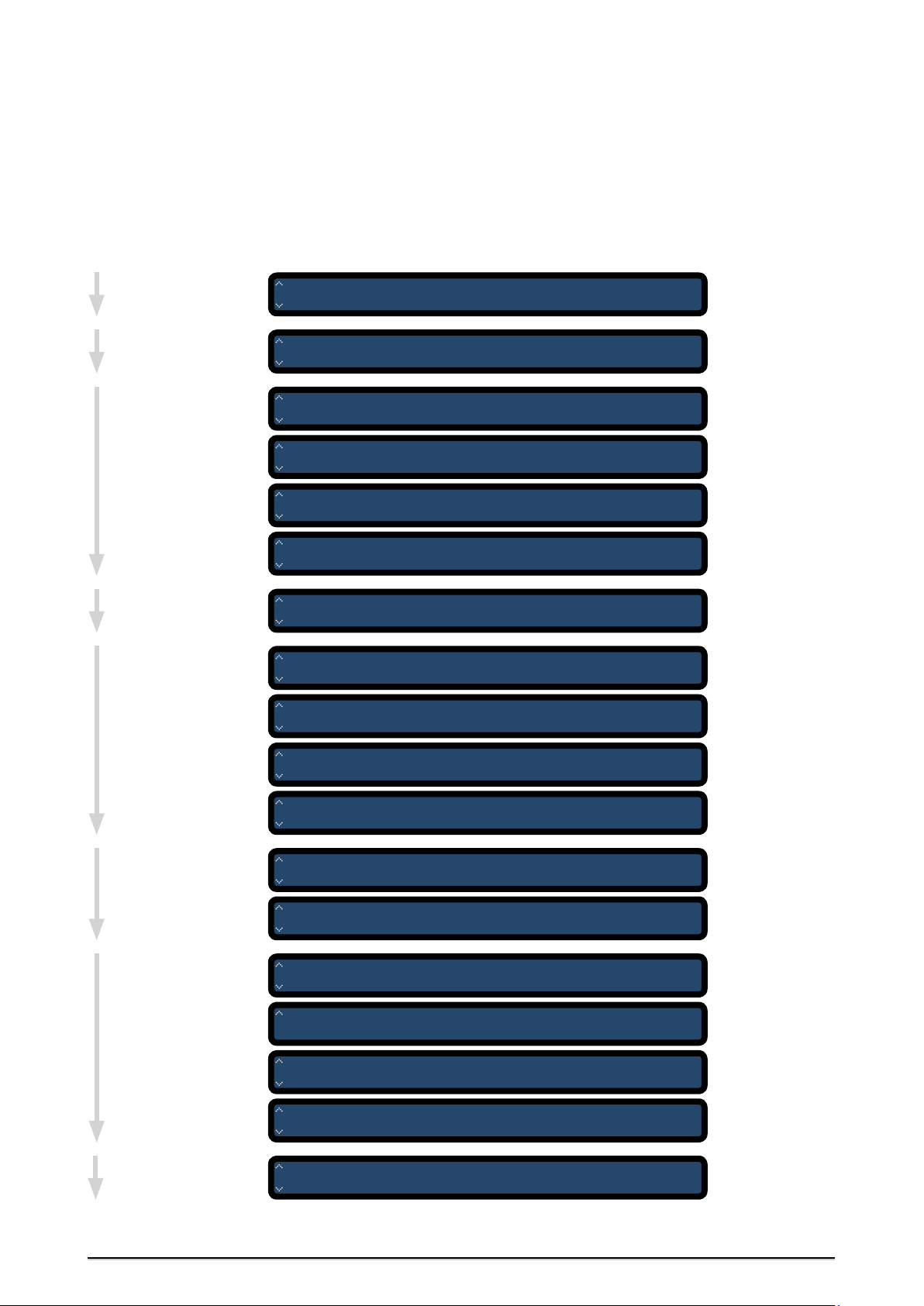
Menu Structure
The entire menu structure is based on the logical flow of events when deploying the iCLOCK in a standard audio/video-studio
environment. Therefore, starting with the menu main page, the menu pages have an ergonomically structured sequence and can
thus be called successively by repeatedly pressing the up button.
Menu main page
REF 1– 3
Setting the clock
sources
WCLK, OUT 1– 4
Setting the wordclock
functions
VIDEO OUT 1+ 2
Setting the videogenerator functions
AES OUT 1+ 2
Setting the AES/EBUgenerator functions
I N P U T R E F 1 S T A T U S O U T P U T s
I N T E R N 2 5 H z L O C K E D W C L K 1 4 4 . 1 k / W
R E F 1 - 3 R E F 1 R E F 2 R E F 3 S Y N C
I N T E R N N O R E F N O R E F R E F 1
W C L K - S F R E Q ( F O R M A T ) L E V E L / T E R M
O U T 1 4 4 . 1 k W O R D C L K 2 . 5 V / 7 5 R
W C L K - S F R E Q ( F O R M A T ) L E V E L / T E R M
O U T 2 4 4 . 1 k W O R D C L K 2 . 5 V / 7 5 R
W C L K - S F R E Q ( F O R M A T ) L E V E L / T E R M
O U T 3 4 4 . 1 k W O R D C L K 2 . 5 V / 7 5 R
W C L K - S F R E Q ( F O R M A T ) L E V E L / T E R M
O U T 4 4 4 . 1 k W O R D C L K 2 . 5 V / 7 5 R
V I D E O R E F F O R M A T V I D E O - T Y P E
O U T 1 + 2 I N T E R N P A L B L A C K + B U R S T
A E S - S F R E Q W O R D L F O R M A T D C S E T
O U T 1 / 1 4 4 . 1 k 2 4 B I T s P R O F O F F
A E S - S A U D I O S T A T R E F S T A T L O C K S T A T
O U T 1 / 2 N O N A U D I O G 1 - R E F L O C K E D
WORD CLOCK OUT 1
page 1
WORD CLOCK OUT 2
page 2
WORD CLOCK OUT 3
page 3
WORD CLOCK OUT 4
page 4
VIDEO OUT 1+ 2
AES/EBU OUT 1
page 1
AES/EBU OUT 1
page 2
S/P-DIF OUT 1
Setting the S/PDIFgenerator functions
GLOBAL 1/ 4
Setting global system
functions
PRESET
Preset management
A E S - S F R E Q W O R D L F O R M A T D C S E T
O U T 2 / 1 4 4 . 1 k 2 4 B I T s P R O F O F F
A E S - S A U D I O S T A T R E F S T A T L O C K S T A T
O U T 2 / 2 N O N A U D I O G 1 - R E F L O C K E D
S / P D I F F R E Q W O R D L F O R M A T D C S E T
O U T / 1 4 4 . 1 k 2 4 B I T s C O N S O F F
S / P D I F A U D I O S T A T R E F S T A T
O U T / 2 N O N A U D I O L E V E L 1
G L O B A L P U L L s V A R I S P E E D P U L L R A N G E
1 / 4 O F F + 0 . 0 0 0 0 % + / - 5 . 0 %
G L O B A L L O N E R E F L O C K T I M E F R E E Z E
G L O B A L L O N E R E F L O C K T I M E F R E E Z E R E S E T
2 / 4 3 0 S E C s 5 S E C s G O
2 / 4 3 0 S E C s 5 S E C s G O G O
G L O B A L A D J W C L K A D J A E S / E B U D I S P L A Y
3 / 4 S I N G L E S I N G L E O N
G L O B A L T E R M I N 1 / I N 2 P O W E R S U P P L Y S O F T
4 / 4 O N O N 1 - O K 2 - N . A . V 2 1 1
P R E S E T O P E R A T I O N N A M E N U M B E R
G O L O A D P R E S E T 0 1 0 1
AES/EBU OUT 2
page 1
AES/EBU OUT 2
page 2
S/P-DIF OUT
page 1
S/P-DIF OUT
page 2
GLOBAL page 1
GLOBAL page 2
GLOBAL page 3
GLOBAL page4
PRESET
>>>>>>>>>>>>>>>>>>>>>>>>>>>>>>>>>>>>>>>>>>>>>>>>>>>>>>>>>>>>>>>>>>>>
88
13
Page 14

OPERATION
FORMATDCSET
PROF OFF
|
AES-S F REQ WORDL FORMATDCSET
OUT1/144.1k 24BITs PROF OFF
|
AES-S F REQ WORDL FORMATDCSET
OUT1/144.1k 24BITs PROF OFF
|
AES-S F REQ WORDL FORMATDCSET
OUT1/1>44.1k24BITsPROFOFF
<
|
<
!
|
OPERATION
OPERATION
\\\\\\\\\\\\
>>>>>>>>>>>>>>>>>>>>>>>>>>>>>>>>>>>>>>>>>>>>>>>>>>>>>>>>>>>>>>>>>>>>
Selecting Menu Pages and setting Functions
The device is fully operated using the display and the four cursor buttons
Safety Instructions
For safety reasons, be sure to
read the SAFETY INSTRUCTIONS
and INSTALLATION chapters before first
powering-up!
We also recommend reading the CONTROL
ELEMENTS chapter for information on how
to connect iCLOCK!
on the front panel. All display screens have an identical operating structure:
1 Arrows on the left display side for simplifying navigation
2 Appropriate page name on the left display side next to the arrows
3 The upper display line shows the function name
4 The lower display line shows the associated adjustable parameter
2 Page Name 3 Function Name
<
AES-S F REQ WORDL
<
OUT1/144.1k 24BITs
<
Selecting different display pages during
operation will not affect the functionality of
iCLOCK. Even changing output function settings will not impede the overall operation!
Display pages not containing a horizontal
arrow are provided for function-status
indication only and cannot be edited.
1 Navigation Arrows
Display operating structure
The arrow orientations refer to the respective cursor buttons.
1 When the two vertical arrows are displayed as normal, pressing the up
and down buttons will move between the individual menu pages.
2 When an arrow pointing to the right is displayed, pressing the right
button (ENTER) will provide access to the adjustable parameter of the
individual functions. With every press of the button, the arrow moves
on to the next parameter of the next function.
1 2
4 Parameter
<
<
<
<
<
<
ENTER
Display arrow orientations
3 During this procedure, the two vertical arrows will be inverted, meaning
that the up and down buttons are now used for changing parameter
values and not for moving between menu pages.
4 When the horizontal arrow has been positioned in front of the parameter to
be changed, pressing the up/down buttons will first change to the setting
mode (the arrow will change its shape). Subsequent pressing the ENTER
button will confirm the changes, the arrow will return to its original shape.
Pressing the ENTER key again will then move the arrow to the next parameter.
If no buttons are operated for approx.
30 seconds, the display will automatically
return to the menu main page.
3 Inverted
Navigation
Arrows
Setting modes and parameters
88
>>>>>>>>>>>>>>>>>>>>>>>>>>>>>>>>>>>>>>>>>>>>>>>>>>>>>>>>>>>>>>>>>>>>
14
4 Enter
setting
mode
Up/down buttons
change operation
modes and values
Page 15

OPERATION
!
|
!
OPERATION
OPERATION
\\\\\\\\\\\\
>>>>>>>>>>>>>>>>>>>>>>>>>>>>>>>>>>>>>>>>>>>>>>>>>>>>>>>>>>>>>>>>>>>>
MENUS AND FUNCTIONS
Main Menu Page
When the device is switched on, a boot period of approximately seven
seconds will occur. During this period, the display will show two pages in
succession. The first of them provides information on the current firmware
version.
i C L O C K - V 2 . 1 1
R E D U N D A N T M U L T I P L E C L O C K S Y N T H E S I Z E R
V I D E O R E F E R E N C E G E N E R A T O R
c M U T E C G m b H 2 0 0 2 - 2 0 0 8
Boot pages
After the boot period, the menu main page will be displayed. This page is
always displayed during standard operation; in combination with the eight
front panel indicators, it provides information on the basic device status.
I N P U T R E F 1 S T A T U S O U T P U T s
I N T E R N 2 5 H z L O C K E D W C L K 1 4 4 . 1 k / W
Menu main page
All user-specific parameter settings
are available furthermore when
power is restored.
INPUT REF1, -2, -3
INPUT REFERENCE, shows an abbreviation of the clock source currently selected incl. its reference slot and its actual rate as a realtime measurement.
As display space is limited, the displayed value is automatically adapted
with regard to the decimal places and the frequency unit as follows:
Hz = hertz
k = kilohertz
M = megahertz
Refer to the »Selecting Clock Sources« section in this chapter for
information on individual sources.
STATUS (function)
Shows the current system status. STATUS provides information on the device
synchronization and possible system errors. Major functionalities are indicated through eight LEDs on the right hand side of the display additionally.
LOCKED (status message)
LOCKED indicates that the system has synchronized to the internal video
reference generator or an externally applied clock signal. At the same time,
the blue LOCK indicator associated with the active clock input (INPUT 1 - 3)
will light.
FQ CHANGE (status message)
FREQUENCY CHANGE indicates that a sync source change is occurring. This
can be a change between two externally applied clock signals or an automatically or manually performed change from an external to an internal
clock source (or vice versa). When the change occurs, the LOCK indicator
of the last clock source used will go dark, and the red HOLD indicator will
light. When the system has locked to the new source, the HOLD indicator
will go dark, and the associated LOCK indicator will light.
HOLD (status message)
HOLD indicates that an externally applied clock signal has either drifted
outside its permitted lock range (see the PULL RANGE parameter on the
GLOBAL 1/4 page) or is completely lost. In this case, the system waits for a
certain period for the signal to return before automatically changing to the
next clock source. This waiting period specified by the LONEREF parameter
on the GLOBAL 2/4 page.
CYCLESYNC (status message)
CYCLE SYNCHRONIZATION indicates that the system is currently performing an automatic resynchronization. This function can be disabled on the
REF1–3 page or be enabled manually for individual clock source inputs.
Status Displays
When iCLOCK is running in INTERN
mode the first blue LED, LOCK REF 1,
will light and confirm the synchronization
of the synthesizer to the internal video
reference generator.
After first switching on, the synthesizer
needs approx. 30 seconds to achieve stable
synchronization. This depends on the time the
video reference generator needs for attuning
all components of its video output signal.
During this process the system re-locks
temporarily (the HOLD LED and the blue
LOCKED REF 1 LED are lightening alternately).
This has no relevance for system security.
The output clocks are constantly available.
88
>>>>>>>>>>>>>>>>>>>>>>>>>>>>>>>>>>>>>>>>>>>>>>>>>>>>>>>>>>>>>>>>>>>>
15
Page 16

ANHANG
|
<
!
!
!
ANHANG
ANHANG
\\\\\\\\\\\\\\\\\\
>>>>>>>>>>>>>>>>>>>>>>>>>>>>>>>>>>>>>>>>>>>>>>>>>>>>>>>>>>>>>>>>>>>>
OSCI FAIL (status message)
OSCILLATOR FAILED, indicates that the internal reference clock oscillator has
failed.
MAIN1LOST (status message)
Error Messages
If one of the messages OSCI FAIL,
MAIN1LOST or MAIN2LOST is
displayed, safe operation is not guaranteed!
Contact the technician in charge
immediately!
MAIN 1 LOST indicates that the primary supply voltage or the primary internal power supply have failed. If this status message is indicated, contact
the technician in charge immediately! The message is displayed only if the
iCLOCK is equipped with a redundant power supply (iCLOCK dp version,
item no. 8015-046).
MAIN2LOST (status message)
MAIN 2 LOST indicates that the secondary supply voltage or the secondary
internal power supply have failed. If this status message is indicated, contact the technician in charge immediately! The message is displayed only if
the iCLOCK is equipped with a redundant power supply (iCLOCK dp version,
item no. 8015-046).
OUTPUTs (function)
Here, the set clock rates of all outputs are displayed alternately as a
»ticker«. This allows for checking the settings directly with no need for
changing to the relevant menu pages.
The following clock signals or rates are factory defaults:
PAL/NTSC VIDEO OUT 1 + 2 = PAL Black + Burst
WORD CLOCK OUT 1 – 4 = 44,1kHz
AES3/-11 OUT 1 + 2 = 44,1kHz
S/P-DIF OUT = 44,1kHz
Activating Clock Sources
After selecting a new clock source
under REF1 – 3, it is imperative to
move the cursor to the SYNC function and
to press ENTER for activating the selected
reference for synchronisation!
Setting REF1 – 3
The most important clock source
in your studio environment should
always be assigned to REF1! This is critical
for proper completion of the CYCLE-SYNC
setting. Afterwards, the other REF slots
should be assigned with sources in a
hierarchical order.
Selecting and activating Clock Sources
The REF1-3 page allows for selecting the clock source of the internal synthesizer. The clock formats supported by iCLOCK are listed in the adjacent table.
The factory defaults are REF1 = INTERN, REF2 = NO REF, REF3 = NO REF.
If one of the synchronizable clock sources is selected, the respective signal
format is marked with an index (1 + 2) referring to the two universal clocksource inputs INPUT 1 and INPUT 2. Thus, the input clock signals can be
routed freely to these two system inputs. The AES format, however, is an
exception as balanced AES/EBU signals can be received by INPUT 3 only.
When selecting clock sources, the system proceeds logically. For example,
if the PAL1 source (PAL video on INPUT 1) has been selected under REF1,
it will not be available anymore for REF2 and REF3. This means that only
sources with an index of »2«, »AES«, »INTERN«, and »NO REF« can be
configured. Likewise, a clock source programmed for REF2 will not be
available for REF3 anymore.
If a clock source is routed to one of the REF slots it has to be activated
for synthesizer synchronization. Therefore the last modified REF slot
is displayed in the SYNC function menu automatically. Moving the
cursor to this position and pressing the ENTER button will activate the
synchronization process to the new clock source immediately.
R E F 1 - 3 R E F 1 R E F 2 R E F 3 S Y N C
I N T E R N N O R E F N O R E F R E F 1
REF1-3 page
REF 1, REF2, REF3 (function)
This function allows for selecting three clock sources supported by the system and for assigning them to a clock source slot. The sources will synchronize the system in their numeric sequence (REF1 → REF2 → REF3).
INTERN (setting)
INTERNAL Selecting the INTERN setting synchronizes the synthesizer to the
internal video reference generator that supplies all audio clock signals in
compliance with AES11 and EBU R83. As internal synchronization is the ultimately selected source, no other sources will be left afterwards. Therefore,
when selecting INTERN for REF1, the REF2 and REF3 functions will automatically be assigned with the »NO REF« setting.
>>>>>>>>>>>>>>>>>>>>>>>>>>>>>>>>>>>>>>>>>>>>>>>>>>>>>>>>>>>>>>>>>>>>
16
88
Page 17

ANHANG
!
ANHANG
ANHANG
\\\\\\\\\\\\\\\\\\
>>>>>>>>>>>>>>>>>>>>>>>>>>>>>>>>>>>>>>>>>>>>>>>>>>>>>>>>>>>>>>>>>>>>
PAL 1, -2 (setting)
PAL1, -2 allows for synchronizing the internal video reference generator to
PAL or SECAM video signals with a frame rate of 25 fps, 625 lines, and a line
frequency of 15.625kHz.
NTSC 1, -2 (setting)
NTSC1, -2 allows for synchronizing the internal video reference generator to
NTSC video signals with a frame rate of 29.97fps, 525 lines, and a line frequency of 15.73425kHz, or 30fps, 525 lines, and a line frequency of 15.750 kHz
(black/white). The two NTSC formats are distinguished automatically.
WCLK 1, -2 (setting)
The WLCK1, -2 setting allows for synchronizing the synthesizer to all audiorelated Word Clock rates within a range of 8.0…24.576MHz. The applied
clock rate is recognized automatically. Refer to the »Synchronizable and
generatable Clock Rates« section in the appendix for a full list of all clock
rates.
AES (setting)
AES allows for synchronizing the synthesizer to all audio-related AES3/-11
rates in a range of 32…192kHz. The applied clock rate is recognized automatically. Both AES 3 or AES 11 compliant signals can be applied. In addition, S/PDIF signals can be applied to this input and be used for synchronization. Refer to the »Synchronizable and Generatable Clock Rates« section in
the appendix for a full list of all clock rates.
AESid 1, -2 (setting)
AESid1, -2 allows for synchronizing the synthesizer to all audio-related
AES3/-11 rates in a range of 32…192kHz. The applied clock rate is recognized automatically. Both AES 3id or AES 11id compliant signals can be
applied. In addition, S/PDIF signals can be applied to this input and be used
for synchronization. Refer to the »Synchronizable and Generatable Clock
Rates« section in the appendix for a full list of all clock rates.
S/P-DIF1, -2 (setting)
S/P-DIF1, -2 allows for synchronizing the synthesizer to all audio-related
S/P-DIF rates in a range of 32…192kHz. The applied clock rate is recognized automatically. Both S/P-DIF audio or S/P-DIF blank frame signals can be
applied. Refer to the »Synchronizable and Generatable Clock Rates« section
in the appendix for a full list of all clock rates.
New References
For special-purpose applications, the range
or number of the sync-clock references can
be extended by means of a software update.
Practically any frequency or frequency
range between 1.0 kHz and 30.0 MHz can be
defined. The only precondition is that the
new clock source can be connected to and
processed by the BNC inputs (INPUT 1 and
INPUT 2) according to their specifications.
For more information or a proposal, send an
e-mail message to
tecsupport@iCLOCK-net.de
You may also call us or send a fax:
Phone 0049-(0)30-746880-0
Fax 0049-(0)30-746880-99
When applying Word Clock, GPS, Telecom,
DCF77 or MFS60 sources, both pulse and sine
signals will be accepted which allows for
processing even heavily slurred signals.
If an option supporting new input clock
formats is installed, these will automatically
be implemented by the system and will be
available for selection on the REF1–3 page.
GPS 1, -2 (setting)
GPS1, -2 allows for synchronizing the synthesizer to all sources with
standard GPS rates (1.0MHz, 2.5MHz, 5.0MHz, and 10.0MHz). The actual
clock rate will be recognized automatically.
TELEC 1, -2 (setting)
TELECOM1, -2 allows for synchronizing the synthesizer to sources providing
the standard Telecom clock rates of 1.024MHz or 2.048MHz. The actual
clock rate will be recognized automatically.
DCF 77 1, -2 (setting)
DCF771, -2 allows for synchronizing the synthesizer to sources providing a
DCF77 clock rate (77.5kHz). This reference is transmitted from Mainflingen /
Germany with a range of approx. 2000kms.
MSF60 1, -2 (setting)
MSF601, -2 allows for synchronizing the synthesizer to sources providing a
MSF60 clock rate (60.0kHz). This reference is transmitted from Rugby / UK
with a range of approx. 1500kms. From April 1st, 2007, it will be transmitted from Anthorn.
HD-P- 1, -2 (setting)
HD-P-1, -2 allows for synchronizing the synthesizer to HD tri-level sync
sources with frame rates of 24Hz, 25Hz, 30Hz, 50Hz, 60Hz.
HD-N- 1, -2 (setting)
HD-N-1, -2 allows for synchronizing the synthesizer to HD tri-level sync
sources with frame rates of 23.98Hz, 29.97Hz, 59.94Hz.
NO REF (setting)
Selecting the NO REF setting disables the respective clock-source slot. If, for
example, only two clock sources are connected to the device and REF1 and
REF2 are configured accordingly, assign the NO REF setting to the REF3 slot
in order to disable this slot for the automatic resynchronization function
(see also CYCLESYNC).
iCLOCKdp to HD tri-level references, their
individual frame rates can not be displayed
correctly under »STATUS«, as it is the case
when locking SD bi-level references. This is
due to system reasons. But your iCLOCK will
be locked as it should be.
Refer to the »Synchronizable HD tri-level
Standards and Frame Rates« section in the
APPENDIX for a full list of all synchronizable
and convertable HD tri-level standards and
frame rates.
Displaying HD tri-level
References
When locking your iCLOCK or
>>>>>>>>>>>>>>>>>>>>>>>>>>>>>>>>>>>>>>>>>>>>>>>>>>>>>>>>>>>>>>>>>>>>
88
17
Page 18

ANHANG
!
!
|
<
ANHANG
ANHANG
\\\\\\\\\\\\\\\\\\
>>>>>>>>>>>>>>>>>>>>>>>>>>>>>>>>>>>>>>>>>>>>>>>>>>>>>>>>>>>>>>>>>>>>
SYNC (function)
As the synthesizer is capable of continuously
supplying the adjusted iCLOCK output
signals, even a manual clock source change
on an input (by replugging the clock lines) is
supported during operation!
It is not important whether the change occurs,
for example, from a PAL SD video signal to a
Word Clock or GPS signal. The set output clock
rates will not be altered; only the base rate
will gradually be updated to match the new
source using iCLOCK‘s SoftReLock functionality
(see chapter iCLOCK TECHNOLOGY).
SYNCHRONIZATION This function allows for manual or automatic synchronization of the synthesizer to selected clock sources assigned to the REF1–3
slots.
SEQSYNC (setting)
SEQUENCE SYNCHRONIZATION This is the default setting when activating
the REF1–3 menu page. It indicates the standard reference synchronization
mode of iCLOCK.
REF 1, REF2, REF3 (setting)
If one of the REF1, REF2, or REF3 parameters is selected and confirmed by
pressing the ENTER button, the synthesizer will immediately synchronize
the clock source assigned to the corresponding REF slot. The output signals
are set or adapted to the new source within the period specified by the
LOCKTIME parameter (see GLOBAL 2/4 page).
CYCLESYNC (setting)
CYCLESYNC is not available when
the LONEREF function is set to HOLD
(see GLOBAL 2/4 menu page).
CYCLE SYNCHRONIZATION With this setting, the input circuit querys the three
inputs for clock source reestablishment by cycling from REF1 to REF2 to REF3
and to the internal video reference generator automatically until a source is
available. The system‘s priority is programmed to the first reference slot (REF1).
Refer to »Sequence Synchronization and Cycle Synchronization« section in the
iCLOCK TECHNOLOGY chapter for details about SEQSYNC and CYCLESYNC.
If the optional second video generator is
installed, it is necessary to split up the video
output pairs between the two generators.
Therefore, two jumpers have to be removed
from their socktes on the mainboard, see the
»Splitting-up the Video Ouputs for dual
Video Generator Operation« section in the
APPENDIX.
Locking the internal Video
Reference Generator – 1
If PAL or NTSC SD video is selected
as external reference, the internal video
reference generator will be automa-tically
gen-locked by the reference source and
switches to the same video format! This guaranties correct phase relationships between
the video source and iCLOCK‘s generated sync
signals. A video format conversion is only
possible using the optional video generator
P/NVSG-02 (Order no. 8010-010) additionally.
With synchronization to PAL or NTSC SD bilevel video it is not possible to change the
clock reference (REF) of the internal video
reference generator!
Configuring the internal Video Reference Generator
The settings of the internal video reference generator and the four video
outputs available with iCLOCK standard version are configured on this
page. Two output pairs comprising one top-row and one bottom-row BNC
output each are available on the rear panel. These are numbered as PAL/
NTSC VIDEO OUT 1 and 2.
V I D E O R E F F O R M A T V I D E O T Y P E
O U T 1 + 2 I N T E R N P A L B L A C K + B U R S T
VIDEO page
VIDEO OUT 1 + 2 (page name)
VIDEO OUT 1 + 2 indicates that the internal video reference generator sends
its signals to both PAL/NTSC VIDEO OUT 1 and 2. This means also that only
one video reference generator is installed.
If the optional second generator is installed, another menu page will automatically be added for it. The page names will change accordingly:
VIDEO OUT 1 = internal video reference generator
VIDEO OUT 2 = optional video generator
REF (function)
REFERENCE This function allows for setting the clock source of the respective video generator and can also enable video signal routing. The factory
default is INTERN.
INTERN (setting)
INTERNAL links the video generator to the internal reference clock oscillator. An extraordinary feature of iCLOCK is that the synthesizer can be synchronized to an external clock source independently of the simultaneously
enabled video generator. Therefore, only the audio-related clock signals
might be subject to any present clock source deviation while the video signals are output with the accuracy of the internal clock: In a way, the video
generator acts as »independent autonomous generator« within iCLOCK.
EXTERN (setting)
EXTERNAL This setting synchronizes the video reference generator to the currently selected external clock source. Any signal or phase relations between
the input clock signals and the selected video format will be recognized automatically and be routed internally in compliance with AES11 and EBU R83.
>>>>>>>>>>>>>>>>>>>>>>>>>>>>>>>>>>>>>>>>>>>>>>>>>>>>>>>>>>>>>>>>>>>>
18
88
Page 19

ANHANG
!
!
ANHANG
ANHANG
\\\\\\\\\\\\\\\\\\
>>>>>>>>>>>>>>>>>>>>>>>>>>>>>>>>>>>>>>>>>>>>>>>>>>>>>>>>>>>>>>>>>>>>
This function also ensures a redundant (failsafe) availability of the video
output signals. If the external source fails temporarily or permanently, the
video generator will continue generating its output signals based on the
last recognized clock rate. If the external source returns to operation, any
differences to the previous rate will gradually be corrected to maintain
flawless on-air operation in e.g. broadcasting environments.
DIST (setting)
DISTRIBUTION This setting allows for forwarding the input video signal
to the video outputs using a hardware bypass. The signal is refreshed by
the video generator output amplifier to ensure a suitable output level; no
other modifications are made to the signal. If the DIST setting has been
selected for REF, the FORMAT and VIDEO TYPE functions cannot be selected
anymore. This is because the video output format is determined by the
input video reference signal.
In this mode, the synthesizer synchronizes to the input video signal to provide the output of phase locked audio clock signals.
FORMAT (function)
FORMAT This function allows for selecting the video format generated and
output by the video generator. The factory default is PAL.
PAL (setting)
PAL With this setting, the video generator produces a PAL-B/G standard definition (SD) video signal compliant with the PAL/CCIR video standard (25 fps,
625 lines, 15,625.0 Hz line frequency). Depending on the REF and VIDEO
TYPE settings, this signal can be output as Black + Burst or composite video
sync. Even when a HD tri-level source is choosed as reference (HD-P-1 / 2), the
PAL setting is possible. Thus the internal video reference generator directly
converts incoming HD references with frame rates of 24Hz, 25Hz, 30Hz, 50Hz
or 60Hz into PAL SD video using its unique cross-locking functionality.
NTSC (setting)
NTSC With this setting, the video generator produces an NTSC standard
definition (SD) video signal (29.97 fps, 525 lines, 15,734.25 Hz line frequency).
Depending on the REF and VIDEO TYPE setting, this signal can be output as
Black + Burst or composite video sync.
Even when a HD tri-level source is choosed as reference (HD-N-1 / 2), the
NTSC setting is possible. Thus the internal video reference generator directly
converts incoming HD references with frame rates of 23.98Hz, 29.97Hz or
59.94Hz into NTSC SD video using its unique cross-locking functionality.
Refer to the »Synchronizable HD tri-level Standards and Frame Rates« section
in the APPENDIX for a list of all convertable HD standards and frame rates.
VIDEO TYPE (function)
VIDEO TYPE This function allows for outputting the previously selected
video format as Black + Burst or composite video sync signal. In addition,
when selecting composite video sync, one of two different output levels
can be set (see below). The factory default is BLACK + BURST.
BLACK + BURST (setting)
BLACK + BURST With this setting, the signal of the previously selected
format will be output as Black + Burst signal. Refer to the »Technical Data«
section in the APPENDIX.
COMPOSITE SYNC 0.3V (setting)
COMPOSITE 0.3V With this setting, the previously selected video format is
output as composite video sync signal with a negative sync signal level of
300 mV (0.3 V).
COMPOSITE SYNC 2.0V (setting)
COMPOSITE 2.0V With this setting, the previously selected video format is output as composite video sync signal with a negative sync signal level of 2.0 V.
Locking the internal Video
Reference Generator – 2
When running the internal video
reference generator in EXTERNAL mode, the
external reference signal may not deviate
more than ±30 ppm from its nominal clock
frequency! Do not try to lock the video
generator to pull up/down clock rates - its
video signal would be destroyed!
DIST does not provide redundancy for the
video outputs. If the external video reference
source fails, the video outputs will fail, too!
Locking the internal Video
Reference Generator – 3
When externally synchronizing the
video reference generator, the lock
and varispeed ranges of the synthesizer will be reduced to ± 30 ppm! Thus,
enabling the pull-up/down and varispeed
factors is not provided in this mode. If,
however, these settings are made, the video
generator will automatically enable internal
synchronization.
When locking the synthesizer to the
internal video reference generator or when
locking the video reference generator to
an external applied reference source, a
synchronization time of approx. 30 seconds
for attuning all components of the video
output signal is required.
During this process the system re-locks
temporarily (the HOLD LED and the blue
LOCKED REF 1 LED are lightening alternately).
This has no relevance for system security.
The output clocks are constantly available.
>>>>>>>>>>>>>>>>>>>>>>>>>>>>>>>>>>>>>>>>>>>>>>>>>>>>>>>>>>>>>>>>>>>>
88
19
Page 20

ANHANG
<
|
ANHANG
ANHANG
\\\\\\\\\\\\\\\\\\
>>>>>>>>>>>>>>>>>>>>>>>>>>>>>>>>>>>>>>>>>>>>>>>>>>>>>>>>>>>>>>>>>>>>
Configuring the Word Clock Outputs
Due to the internal signal phase corrections
the synthesizer can re-lock temporarily when
switching Word Clock clock frequencies.
This does not affect the output signals or
functionality of iCLOCK.
The WCLK OUT 1–4 display pages allow for configuring the eight wordclock
outputs provided by the iCLOCK standard version . Four output pairs
comprising one top-row and one bottom-row output each are available on
the rear panel. These are numbered as WORD CLOCK OUT 1–4. The BNC
terminals making up a pair are marked as »A« and »B«, thus allowing for a
simple documentation of the connected devices.
W C L K - S F R E Q ( F O R M A T ) L E V E L / T E R M
O U T 1 4 4 . 1 k W O R D C L K 2 . 5 V / 7 5 R
WCLK page
WCLK - S, WCLK - L (page name)
Word Clock rates are set independently
of externally applied clocks. Thus, iCLOCK
provides Word Clock conversion from all
supported input rates to all generatable
output rates!
WORD CLOCK – SINGLE, – LINKED, The »S« and »L« letters indicate the Single and Linked modes. Refer to the »ADJ-WCLK« parameter on the GLOBAL
3/4 page explained in the OPERATION chapter, »Setting System Functions«
for more information. The factory default is Single mode (– S).
OUT 1 - 4 (page name)
OUT 1 – 4 is the Word Clock out pair that can be configured on the current page.
FREQ (function)
FREQUENCY sets the clock rate of the selected output pair. The factory
default is 44.1 kHz.
24Hz...60Hz, 8.0kHz...24.576MHz (setting)
Altogether 36 different audio-related clock rates between 8.0 kHz and
GPS / Atomic Clock + Audio Player
References
As so-called GPS or atomic clock references,
the iCLOCK and iCLOCKdp are able to lock
and generate the following frequencies:
1.0Mhz, 2.5MHz, 5.0MHz, 10.0MHz
Furthermore, the iCLOCK and iCLOCKdp are
able to generate the following basic clock
rate used in e.g. CD players:
16.9344MHz
This clock signal can be used to replace a
CD player‘s internal system clock with the
16.9344MHz clock signal generated by the
iCLOCK or iCLOCKdp. Thus, a CD player
can benefit from the iCLOCK‘s lowest-jitter
clock generation which leads to an audible
sound improvement of the CD player‘s DA
converters!
Before replacing your CD player‘s internal
basic clock, check carefully if the frequency
of 16.9344MHz is the right one for your CD
player!
24.576 MHz can be selected individually for each Word Clock output pair.
Also 8 pilot tone clock rates from 24 Hz to 60 Hz are available for synchronizing pilot tone resolvers, timecode generators or film projectors and 5 different high-accurate clock references known from GPS receivers or atomic
clock generators. The individual rates are shortly described under
<
FORMAT>. Refer to the »Synchronizable and Generatable Clock Rates«
section in the appendix for a full list of all clock rates.
‹FORMAT› (message)
FORMAT provides information on the output format of the currently selected Word Clock out pair. This parameter is provided for information purposes only (this is why it is displayed in brackets.) Setting is made against the
setting of the FREQ parameter. The factory default is WORDCLK.
WORDCLK (setting)
WORD CLOCK This setting means that the rate is output as set.
SUPERCLK (setting)
The SUPER CLOCK function is available for Word Clock rates of 44.1 or
48 kHz only. It is used for a rate adaptation required for Digidesign ProTools™ systems (not! ProTools HD™). Accordingly, the 44.1 kHz and 48 kHz
rates are available twice for selection: for both the WORDCLK and the
SUPERCLK, for ProTools™ systems, settings.
FILM FR (setting)
FILM FRAME RATE, 24 Hz
FILM FI (setting)
FILM FIELD RATE, 48 Hz
PAL FR (setting)
PAL VIDEO FRAME RATE, 25 Hz
PAL FI (setting)
PAL VIDEO FIELD RATE, 50 Hz
NTSC FRBW (setting)
NTSC VIDEO FRAME RATE, 30 Hz
NTSC FRC (setting)
NTSC VIDEO FRAME RATE, 29.97 Hz
NTSC FIC (setting)
NTSC VIDEO FIELD RATE, 54.94 Hz
DSD64 (setting)
DSD clock rate, 2.8224 MHz
DSD128 (setting)
DSD double clock rate, 5.6448 MHz
DXD (setting)
DXD clock rate, 352.8 kHz
NTSC FIBW (setting)
NTSC VIDEO FIELD RATE, 60 Hz
>>>>>>>>>>>>>>>>>>>>>>>>>>>>>>>>>>>>>>>>>>>>>>>>>>>>>>>>>>>>>>>>>>>>
20
88
Page 21

ANHANG
|
<
|
<
|
<
|
<
ANHANG
ANHANG
\\\\\\\\\\\\\\\\\\
>>>>>>>>>>>>>>>>>>>>>>>>>>>>>>>>>>>>>>>>>>>>>>>>>>>>>>>>>>>>>>>>>>>>
LEVEL / TERM (function)
LEVEL / TERMINATION This function allows for adjusting the Word Clock
signal level of the selected output pair and for entirely disabling the
output. The page always displays the output level and the corresponding
internal termination of the output pair. The factory default is 2.6 V/75 R.
2.5 V / 75 R (setting)
With this setting, the Word Clock signal is output with a level of 2.6 V and
an internal termination of 75 Ω .
3.5 V / 22 R (setting)
With this setting, the Word Clock signal is output with a level of 3.5 V and
an internal termination of 22 Ω. This setting is recommended for Word
Clock signals to be transmitted over great distances.
SC adapted (setting)
SUPER CLOCK adapted This is no adjustable setting but a status message
used only for clock rates set to Super Clock. Here, the level cannot be modified but only be disabled if required (OFF).
OFF (setting)
OFF disables the selected Word Clock out pair.
More Clock Frequencies
For special-purpose applications, the range
or number of the output clock frequencies
can be extended by means of a software
update. Practically any frequency or frequency range between 1.0 Hz and 25.0 MHz
can be defined and can then be selected for
all Word Clock outputs, providing the same
functionality as the standard frequencies.
For more information or a proposal, send an
e-mail message to
tecsupport@iCLOCK-net.de
You may also call us or send a fax:
Phone 0049-(0)30-746880-0
Fax 0049-(0)30-746880-99
Configuring the AES/EBU Outputs
The four AES/EBU outputs can be set to various clock rates by pairs. In
addition, the channel-status bits can be modified individually.
A E S - S F R E Q W O R D L F O R M A T D C S E T
O U T 1 / 1 4 4 . 1 k 2 4 B I T s P R O F O F F
First AES/EBU output pair, page 1
A E S - S A U D I O S T A T R E F S T A T L O C K S T A T
O U T 1 / 2 N O N A U D I O G 1 - R E F L O C K E D
First AES/EBU output pair, page 2
A E S - S F R E Q W O R D L F O R M A T D C S E T
O U T 2 / 1 4 4 . 1 k 2 4 B I T s P R O F O F F
Second AES/EBU output pair, page 1
A E S - S A U D I O S T A T R E F S T A T L O C K S T A T
O U T 2 / 2 N O N A U D I O G 1 - R E F L O C K E D
Second AES/EBU output pair, page 2
AES - S, AES - L (page name)
AES – SINGLE, – LINKED The »S« and »L« letters shown on each of the two
AES/EBU menu pages indicate the Single and Linked modes. Refer to the
ADJ-AES/EBU parameter on the GLOBAL 3/4 page explained in the SETTING
SYSTEM FUNCTIONS chapter for more information. The factory default is
Single mode (– S).
OUT 1/1, -1/2, -2/1, -2/2 (page name)
The page name contains the selected AES/EBU-output pair (1 or 2) and the
number of the currently displayed menu page. The pages AES OUT 1/1 and
AES OUT 1/2 allow for configuring the first output pair while the pages AES
OUT 2/1 and AES OUT 2/2 are used for the second output pair.
When a certain Word Clock out pair is not
required, disabling it can be reasonable, for
example, to reduce extra device radiation,
thus improving the EMC conditions in the
studio.
(EMC = electromagnetic compatibility)
Due to the internal signal phase corrections
the synthesizer can re-lock temporarily
when switching AES/EBU clock frequencies.
This does not affect the output signals or
functionality of iCLOCK.
Functions and settings on the first page of each AES/EBU output pair:
FREQ (function)
FREQUENCY Sets the clock rate of the selected AES/EBU output pair. A socalled AES11 clear-frame signal (compliant to AES 11-1997/2003) is generated. The factory default is 44.1kHz.
16.0...192.0kHz (setting)
Altogether twelve different clock rates between 16.0...192.0 kHz can be
individually selected for each AES/EBU-out pair. Refer to the »Synchronizable and Generatable Clock Rates« section in the appendix for a full list of all
clock rates.
>>>>>>>>>>>>>>>>>>>>>>>>>>>>>>>>>>>>>>>>>>>>>>>>>>>>>>>>>>>>>>>>>>>>
AES3/-11 clock rates are set independently
of externally applied clocks. Thus, iCLOCK
provides AES3/-11 clock conversion from all
supported input rates to all generatable
output rates!
88
21
Page 22

ANHANG
ANHANG
ANHANG
\\\\\\\\\\\\\\\\\\
>>>>>>>>>>>>>>>>>>>>>>>>>>>>>>>>>>>>>>>>>>>>>>>>>>>>>>>>>>>>>>>>>>>>
DIST (setting)
DIST does not provide redundancy for the
AES/EBU outputs. If the external AES/EBU or
S/P-DIF clock source fails, the associated
AES/EBU-output pair will fail, too!
DISTRIBUTION This setting allows for forwarding an input AES3 or S/P-DIF
signal to the selected AES/EBU output pair using a hardware bypass. As no
adjustments can be made in this mode, the other functions and parameters
will be hidden, and the second menu page of the AES/EBU pair will not
be accessible; the parameters and functions can only be accessed after the
internal AES11 generator has been enabled by selecting a different clock
rate.
In this mode, the synthesizer synchronizes to the input AES3 or S/P-DIF signal; thus, the video and audio clock signals provided at the other outputs
are linked with phase lock to the input signal.
WORDL (function)
If the consumer format is selected, the
physical parameters of the output terminals
(balanced operation, level, and impedance)
will remain unchanged!
The functions and settings displayed on the
AES menu pages are automatically adapted
with regard to the channel-status bits of the
consumer format.
WORD LENGTH This function allows for changing the word length stored in
the channel status bits (byte 2, bits 3, 4 and 5) of the clear-frame signal of
the selected AES/EBU output pair. The factory default is 24BITs.
16BITs, 18BITs, 20BITs, 24BITs (setting)
One of four word lengths between 16 and 24Bits are available for selection.
FORMAT (function)
FORMAT This function allows for altering the AES format stored in the
channel status bits (byte 0, bit 0) of the blank frame signal of the selected
AES/EBU output pair. The factory default is PROF.
PROF, CONS (setting)
PROF, CONS This setting allows for toggling the AES11 blank frame signal
between consumer (CONS) and professional (PROF) formats.
Example
There are AES3/-11 receiver circuits causing
problems when synchronizing to AES11
blank frame signals. This usually results in
increased jitter and signal instabilities. Enabling a DC-offset level in the AES11 blank
frame signal will allow for synchronizing any
AES3/-11 input stage. This level can normally
be processed without problems by the concerning AES3/-11 input stages, thus ensuring
reliable synchronization.
DCSET (function)
DC OFFSET This function allows for applying a DC-offset signal level of
approx. 200 mV to the output AES11 blank frame signal.
ON, OFF (setting)
This will enable (ON) or disable (OFF) the DC-offset signal level in the
AES/EBU blank frame signal.
Functions and settings on the second page of each AES/EBU output pair:
AUDIOSTAT (function)
AUDIOSTATUS This function allows for setting the audio status stored in the
channel status bits (byte 0, bit 1) of the blank frame signal of the selected
AES/EBU output pair. The factory default is NONAUDIO.
NORMAUDIO, NONAUDIO (setting)
These settings allows for selecting the norm-audio or non-audio statuses.
REFSTAT (function)
REFERENCE STATUS, This function allows for changing the reference status
stored in the channel status bits (byte 4, bits 0, 1) of the blank frame signal
of the selected AES/EBU output pair. The factory default is G1-REF.
G1-REF (setting)
GRADE 1 REFERENCE With this setting (grade 1 reference), the AES11 blank
frame signal is output in compliance with AES11, Grade 1.
G2-REF (setting)
GRADE 2 REFERENCE With this setting (grade 2 reference), the AES11 blank
frame signal is output in compliance with AES11, Grade 2.
NO REF (setting)
NO REFERENCE This setting indicates that the AES11 blank frame signal is
not a reference signal compliant to AES11.
>>>>>>>>>>>>>>>>>>>>>>>>>>>>>>>>>>>>>>>>>>>>>>>>>>>>>>>>>>>>>>>>>>>>
22
88
Page 23

ANHANG
|
<
|
<
ANHANG
ANHANG
\\\\\\\\\\\\\\\\\\
>>>>>>>>>>>>>>>>>>>>>>>>>>>>>>>>>>>>>>>>>>>>>>>>>>>>>>>>>>>>>>>>>>>>
LOCKSTAT (function)
LOCK STATUS This function allows for changing the synchronization status
stored in the channel status bits (byte 0, bit 5) of the clear-frame signal of
the selected AES/EBU output pair. The factory default is LOCKED.
If the selected AES/EBU output pair is operated in consumer mode, this
parameter is not available due to the modified structure of the channelstatus bits!
LOCKED, UNLOCKED (Parameter)
LOCKED, UNLOCKED These settings allow for toggling between the locked
and unlocked statuses.
Configuring the S/P-DIF Outputs
A clock rate can be set for both S/P-DIF outputs similarly. The channel-status
bits can be modified, too.
S / P D I F F R E Q W O R D L F O R M A T D C S E T
O U T / 1 4 4 . 1 k 2 4 B I T s C O N S O F F
S/PDIF outputs, page 1
S / P D I F A U D I O S T A T R E F S T A T
O U T / 2 N O N A U D I O L E V E L 3
S/PDIF outputs, page 2
S/PDIF OUT /1, -/2 (page name)
The page names refer to the respective S/P-DIF menu page (see above
figures).
Functions and settings on the first S/P-DIF output page:
FREQ (function)
FREQUENCY Sets the clock rate of the S/P-DIF outputs. A so-called S/P-DIF
clear frame signal (in compliance with AES11) is generated. This signal
does not contain any audio information (data bits). The factory default is
44.1kHz.
16.0...192.0kHz (setting)
Altogether twelve different clock rates between 16.0 kHz and 192.0 kHz
can be selected. Refer to the »Synchronizable and Generatable Clock Rates«
section in the appendix for a full list of all clock rates.
DIST (setting)
DISTRIBUTION This setting allows for forwarding an input S/P-DIF or
AES3/-11 signal to the S/P-DIF output pair using a hardware bypass. As no
adjustments can be made in this mode, the other functions and parameters
will be hidden, and the second menu page of the S/P-DIF pair will not be
accessible; the parameters and functions can only be accessed after the
internal S/P-DIF generator has been enabled by selecting a different clock
rate.
In this mode, the synthesizer synchronizes to the input S/P-DIF or AES3/-11
signal; thus, the video and audio clock signals provided at the other outputs
are linked with phase lock to the input signal.
Due to the internal signal phase corrections
the synthesizer can re-lock temporarily
when switching S/P-DIF clock frequencies.
This does not affect the output signals or
functionality of iCLOCK.
S/P-DIF clock rates are set independently
of externally applied clocks. Thus, iCLOCK
provides S/P-DIF clock conversion from all
supported input rates to all generatable
output rates!
DIST does not provide redundancy for the
S/P-DIF outputs. If the external S/P-DIF or
AES3/-11 signal source fails, the S/P-DIF
output pair will fail, too!
WORDL (function)
WORD LENGTH This function allows for changing the word length stored in
the channel status bits of the S/P-DIF clear-frame signal.
The factory default is 24BITs.
16BITs, 18BITs, 20BITs, 24BITs (setting)
One of four word lengths between 16 and 24Bits are available for selection.
>>>>>>>>>>>>>>>>>>>>>>>>>>>>>>>>>>>>>>>>>>>>>>>>>>>>>>>>>>>>>>>>>>>>
88
23
Page 24

ANHANG
ANHANG
ANHANG
\\\\\\\\\\\\\\\\\\
>>>>>>>>>>>>>>>>>>>>>>>>>>>>>>>>>>>>>>>>>>>>>>>>>>>>>>>>>>>>>>>>>>>>
FORMAT (function)
If the professional format is selected,
the physical parameters of the output
terminals (unbalanced operation, level, and
impedance) will remain unchanged!
The functions and settings displayed on
the S/P-DIF menu pages are automatically
adapted with regard to the channel-status
bits of the professional format.
FORMAT This function allows for altering the S/P-DIF format stored in the
channel status bits (byte 0, bit 0) of the S/P-DIF blank frame signal. The
factory default is CONS.
PROF, CONS (setting)
PROF, CONS This setting allows for toggling the S/P-DIF blank frame signal
between consumer (CONS) and professional (PROF) formats.
DCSET (function)
DC-OFFSET This function allows for applying a DC-offset signal level of approx. 200 mV to the output S/P-DIF blank frame signal. The factory default
is OFF.
ON, OFF (setting)
Example
There are S/P-DIF receiver circuits causing
problems when synchronizing to S/P-DIF blank
frame signals. This usually results in increased
jitter and signal instabilities. Enabling a DCoffset level in the S/P-DIF blank frame signal
will allow for synchronizing any S/P-DIF input
stage. This level can normally be processed without problems by the concerning S/P-DIF input
stages, thus ensuring reliable synchronization.
This will enable (ON) or disable (OFF) the DC-offset signal level in the S/PDIF blank frame signal.
Functions and settings on the second S/P-DIF output page:
AUDIOSTAT (function)
AUDIOSTATUS This function allows for setting the audio status stored in
the channel status bits (byte 0, bit 1) of the S/P-DIF blank frame signal. The
factory default is NONAUDIO.
NORMAUDIO, NONAUDIO (setting)
These settings allows for selecting the norm-audio or non-audio statuses.
REFSTAT (function)
REFERENCE STATUS This function allows for changing the reference status
stored in the channel status bits (byte 3, bits 4, 5) of the clear-frame signal
of the selected S/P-DIF output pair. The factory default is LEVEL 3.
LEVEL 3 (setting)
With the LEVEL 3 (variable) setting, the S/P-DIF blank frame signal is output
with no information on clock accuracy.
LEVEL 2 (setting)
With the LEVEL 2 setting, the S/P-DIF blank frame signal is output with a
clock accuracy of ±1000 ppm.
LEVEL 1 (setting)
With the LEVEL 2 setting, the S/P-DIF blank frame signal is output with a
clock accuracy of ±50 ppm.
>>>>>>>>>>>>>>>>>>>>>>>>>>>>>>>>>>>>>>>>>>>>>>>>>>>>>>>>>>>>>>>>>>>>
24
88
Page 25

ANHANG
|
<
!
ANHANG
ANHANG
\\\\\\\\\\\\\\\\\\
>>>>>>>>>>>>>>>>>>>>>>>>>>>>>>>>>>>>>>>>>>>>>>>>>>>>>>>>>>>>>>>>>>>>
Setting System Functions
System parameters allow for setting functions that affect no specific output
clock formats but all output signals or the global device functionality of
iCLOCK. Four menu pages named GLOBAL 1/4 to GLOBAL 4/4 are provided
by iCLOCK standard version.
Functions and settings on the GLOBAL 1/4 menu page:
G L O B A L P U L L s V A R I S P E E D P U L L R A N G E
1 / 4 O F F + 0 . 0 0 0 0 % + / - 5 . 0 %
GLOBAL 1 / 4
GLOBAL 1/4, 2/4, 3/4, 4/4 (page name)
Specifies the name of the currently selected GLOBAL page.
Setting Pulls and Varispeed
PULLs (function)
With iCLOCK standard version, four different pull-up/down corrective factors
can be set for film–video–audio transfers. These settings only affect audio
clock signals but not video generator signals. The factory default is OFF.
OFF (setting)
OFF With this setting, all audio clock signal rates will be output unchanged.
+
0.1 % (setting)
+
0,1 % This setting will increase all audio clock output rates by 0.1 %. This
factor is required for transferring NTSC video to film.
the device!
Unlike conventional clock generators,
iCLOCK is capable of synthesizing pull-up/
down factors and varispeed in every mode
of operation. This is regardless of whether
the synthesizer is synchronized internally or
by an external source!
PULL and VARISPEED settings will
be not stored when switching-off
- 0.1 % (setting)
-
0,1 % This setting will decrease all audio clock output rates by 0.1 %. This
factor is required for transferring film to NTSC video.
+
4.16 % (setting)
+
4,16 % This setting will increase all audio clock output rates by 4.1666 %.
This factor is required for copying film to PAL video.
- 4.0 % (setting)
- 4,0 % This setting will decrease all audio clock output rates by 4.0 %. This
factor is required for transferring PAL video to film.
VARISPEED (function)
VARISPEED This function allows for detuning the synthesizer in steps of
0.0001 % in relation to the selected nominal rate (e.g. 44.1 kHz, 96.0 kHz, etc.).
The maximum setting range of the varispeed function is ± 20.0 % but may be
limited by settings such as the pull-up/down factors or the pull range as well
as by instabilities of the synthesizer signal caused by clock source deviation.
More Pull-Up/Down Factors
For special-purpose applications, new pull-up/
down factors can be implemented into the system by means of a software update. Practically
any factor or algorithm can be applied. The
synthesizing accuracy is in the µHz range.
For more information or a proposal, send an
e-mail message to
tecsupport@iCLOCK-net.de
You may also call us or send a fax:
Phone 0049-(0)30-746880-0
Fax 0049-(0)30-746880-99
1
Enable the varispeed function by pressing the up/down cursor buttons
one time. (The cursor automatically jumps to the rightmost digit)
x
3
Move the cursor to the desired digit (e.g. 0.1%) using the left cursor button.
Select the desired value with the up/down cursor buttons (e.g. 1 x + 0.1%)
x
1
ENTER
Confirm the setting by pressing the ENTER button.
Entering varispeed values and moving the cursor
>>>>>>>>>>>>>>>>>>>>>>>>>>>>>>>>>>>>>>>>>>>>>>>>>>>>>>>>>>>>>>>>>>>>
1
x
The synthesizer is synchronized to an external
source with a detuning of –5%. In addition,
a varispeed of –16% has been configured.
In this case, the synthesizer would correct its
output rate only to an amount of –15% of
the set varispeed as the total detuning of the
input source and the varispeed are –21%,
which exceeds the permitted range by 1%.
Varispeed values are set using the up/down
cursor buttons. Note that the change will
be applied as the button is pressed. Pressing
ENTER will confirm the selected value.
88
25
x
Example
Page 26

ANHANG
!
<
|
ANHANG
ANHANG
\\\\\\\\\\\\\\\\\\
>>>>>>>>>>>>>>>>>>>>>>>>>>>>>>>>>>>>>>>>>>>>>>>>>>>>>>>>>>>>>>>>>>>>
+
0.0000 % (setting)
The varispeed factor can be set here in miniature steps of 0.0001 %. The
step width can be changed by moving the cursor (see figure at page 25).
The factory default is + 0.0000 %.
PULL RANGE (function)
Example
The synthesizer is synchronized to an external
source with a detuning of +2%. A pull range
setting of ±5.0% is selected, and an extra
varispeed of –10% has been configured. In
this case, the synthesizer would correct its
output rate only to an amount of –7% of its
current setting +2%. The detuning of the
input source and the set pull range are added
to define the maximum rate change. The
factory default is +/-5.0%.
PULL RANGE refers to the limit for the synthesizer to follow the deviation
of its clock source. This is regardless of whether the deviation is caused by
the source itself or by pull-up/down or varispeed settings. The pull range
includes positive and negative differences of up to ±20.0% of the nominal
clock source rate.
+/-
1.0 % ... +/-20.0 % (setting)
The pull range can be set here in steps of 1.0 %.
Functions and settings on the GLOBAL 2/4 menu page:
G L O B A L L O N E R E F L O C K T I M E F R E E Z E R E S E T
2 / 4 3 0 S E C s 5 S E C s G O G O
GLOBAL 2 / 4
LONEREF (function)
Setting LONEREF + LOTIME
The time constants selected for
the LONEREF function are always
greater than the LOTIME values. The system
automatically corrects equal or smaller
LONEREF values to avoid conflicts during
the synchronization flow!
HOLD is not available when the system synchronization function SYNC (see
REF1–3 menu page) is set to CYCLESYNC!
LOCK NEXT REFERENCE The function allows for setting a period of time
that the synthesizer will wait after a clock-source failure before automatically selecting the next source according to the REF1–3 settings. During this
time, all output signals are still available according to their respective setting. If the failed source returns to operation within the time defined here,
the synthesizer will resynchronize to it. The factory default is 1 MIN.
30SECs, 1MIN, 10MINs, 30MINs, 60MINs (setting)
One of five time settings between 30 seconds and 60 minutes can be selected here.
HOLD (setting)
With this setting, the synthesizer will enter a mode of operation where it
waits until the previously lost clock source returns. The output rate is set
based on the last recognized clock rate.
ENTER
1) Press the ENTER button and hold.
2) Press the up button additionally.
Canceling the FREEZE function
LOTIME (function)
LOCK TIME The Lock Time function sets a period required by the synthesizer
to update its clock rate from the previously selected source to a subsequently selected source. The factory default is 5 SECs.
5SECs, 30SECs, 1MIN, 10MINs, 30MINs (setting)
One of five time settings between 5 seconds and 30 minutes for updating
rate differences between the original and a subsequently selected clock
source can be selected here.
FREEZE (function)
FREEZE This function allows for blocking the four cursor buttons. This is
convenient for protecting the iCLOCK from unauthorized access. FREEZE
can be canceled by pressing the ENTER and up buttons simultaneously.
+
GO, SURE ? (setting)
GO enables the FREEZE function. When the ENTER button has been
pressed, a confirmation request (SURE ? ) will be displayed. If this request is
confirmed by pressing the ENTER button again, the display automatically
jumps to the menu main page. From that moment, the four cursor buttons
are out of operation until the FREEZE function is canceled by using the key
combination mentioned on the left.
>>>>>>>>>>>>>>>>>>>>>>>>>>>>>>>>>>>>>>>>>>>>>>>>>>>>>>>>>>>>>>>>>>>>
26
88
Page 27

ANHANG
|
<
ANHANG
ANHANG
\\\\\\\\\\\\\\\\\\
>>>>>>>>>>>>>>>>>>>>>>>>>>>>>>>>>>>>>>>>>>>>>>>>>>>>>>>>>>>>>>>>>>>>
RESET (function)
RESET This function allows for resetting all function and parameter changes
to their respective factory defaults, i.e. to the settings of the iCLOCK when
it is switched on for the first time.
GO, SURE ? (setting)
GO enables the RESET function. When the ENTER button has been pressed,
a confirmation request (SURE?) will be displayed. If this request is confirmed by pressing the ENTER button again, all current settings will irreversibly be reset to their defaults, and the display will change to the menu main
page.
Functions and settings on the GLOBAL 3/4 menu page:
G L O B A L A D J W C L K A D J A E S / E B U D I S P L A Y
3 / 4 S I N G L E S I N G L E O N
GLOBAL 3 / 4
ADJ WCLK (function)
ADJUST WORD CLOCK This function allows for editing the four wordclock
outputs in common. If a function is edited on any wordclock menu page,
any changes will be applied to the same function on all other wordclock
menu pages or outputs. This also applies to the outputs of an installed
wordclock expansion. The factory default is SINGLE.
SINGLE (setting)
SINGLE allows for editing the wordclock outputs individually.
Example
If a studio is to be synchronized with an
equal clock rate, setting the Word Clock and
AES/EBU outputs to LINKED is reasonable
in order to avoid unnecessary editing on
multiple menu pages.
LINKED (setting)
LINKED allows for editing the four Word Clock outputs together by making
settings on any Word Clock menu page.
ADJ AES/EBU (function)
ADJUST AES/EBU This function allows for editing the two AES/EBU outputs
in common. If a function is edited on any AES menu page, any changes will
be applied to the same function on the other AES menu page or output.
The factory default is SINGLE.
SINGLE (setting)
SINGLE allows for editing the AES/EBU outputs individually.
LINKED (setting)
LINKED allows for editing the two AES/EBU outputs together by making
settings on any AES menu page.
DISPLAY (function)
DISPLAY This function allows for choosing whether the backlight LEDs light
permanently or whether they will be switched off automatically after a
defined period of time. The factory default is ON.
ON (setting)
ON lets the backlight LEDs light permanently.
AUTO (setting)
AUTOMATICALLY turns the backlight LEDs after a period of 5 minutes off.
Pressing one of the four buttons on the front panel reactivates the backlight LEDs.
Recommendation
Setting the display to the AUTO mode helps
saving energy and keeps the lifetime of the
backlight LEDs.
Furthermore, it will not disturb a reduced
illuminated studio environment.
>>>>>>>>>>>>>>>>>>>>>>>>>>>>>>>>>>>>>>>>>>>>>>>>>>>>>>>>>>>>>>>>>>>>
88
27
Page 28

ANHANG
!
|
ANHANG
ANHANG
\\\\\\\\\\\\\\\\\\
>>>>>>>>>>>>>>>>>>>>>>>>>>>>>>>>>>>>>>>>>>>>>>>>>>>>>>>>>>>>>>>>>>>>
Functions and settings on the GLOBAL 4/4 menu page:
G L O B A L T E R M I N 1 / I N 2 P O W E R S U P P L Y S O F T
4 / 4 O N O N 1 - O K 2 - N . A . V 2 1 1
GLOBAL 4 / 4
This menu page provides information in internal system statuses and
cannot be edited.
TERM IN1 / IN2
TERMINATION - INPUT1 / INPUT2 This informs on the internal termination
status of the two universal clock-source inputs INPUT1 and INPUT2. The
factory default is ON for both inputs.
ON = internal termination enabled
OFF = internal termination disabled
Refer to the »Configuring the Terminations« section in the appendix.
POWER SUPPLY
POWER SUPPLY This informs on the status of the internal power supplies
Failure Messages
If one of the statuses 1-FAIL or
2-FAIL is indicated (iCLOCK dp only),
safe operation is not guaranteed! Contact
the technician in charge immediately!
and shows how many of them are active. The iCLOCK standard version is
shipped with one power supply while the iCLOCK dp version contains two
power supplies to ensure redundant (failsafe) operation.
The factory defaults are:
iCLOCK standard version:
iCLOCK dp: 1-ON 2-ON (two active power supplies)
OK (setting)
The respective power supply is active.
N.A. (setting)
NOT AVALABLE This message shows that the respective power supply is not
available (only when using the iCLOCK basic version).
LOST (setting)
LOST indicates that a power supply has failed or that the external mains
voltage is not available (iCLOCK dp only).
1-ON 2-N.A. (one active power supply)
SOFT
SOFTWARE VERSION This informs on the currently installed operating system of your iCLOCK or iCLOCKdp.
V220 (setting)
These letters and numbers represent the currently installed software version of iCLOCK or iCLOCKdp:
V = Version
220 = 2.20
>>>>>>>>>>>>>>>>>>>>>>>>>>>>>>>>>>>>>>>>>>>>>>>>>>>>>>>>>>>>>>>>>>>>
28
88
Page 29

ANHANG
|
!
!
ANHANG
ANHANG
\\\\\\\\\\\\\\\\\\
>>>>>>>>>>>>>>>>>>>>>>>>>>>>>>>>>>>>>>>>>>>>>>>>>>>>>>>>>>>>>>>>>>>>
Preset Management
This functionality is available from software versions, V2.10 and V2.11, or
higher. Does your iCLOCK or iCLOCKdp not include one of these software
versions, please contact your local MUTEC dealer or distributor for an update.
Software V2.11 offers in combination with the new optional iC-ALARM/GPI
interface the possibility to switch over different presets externally via GPIO
control. If you are working with software V2.10, you need to switch over
the presets on the PRESET page.
P R E S E T O P E R A T I O N N A M E N U M B E R
G O L O A D P R E S E T 0 1 0 1
PRESET
for one time to reach the PRESET page
immediately.
Entering the Preset Page
Starting from the main page, press
the button pointing downwards
The preset management enables to store eight different set-ups of all function settings which have been set within the whole iCLOCK system menu, as
so-called ‚Presets‘. When switching over the presets, all individual function
settings will be switched at one time. Additionally, the preset management
stores intermediately the whole current system status permanently in a socalled ‚System-Preset‘. This system-preset works fail-safe, which provides an
automatic function-setting-recovery after, e.g., a mains failure!
When switching on your iCLOCK or iCOCKdp for the first time, all presets
contain of the same factory default settings as described in the previous
chapters of this manual. This system condition is equal to this one after a
software-reset.
After normal switching on the unit, the last system status stored in the
system-preset will be loaded. If this is different compared to the settings of
the last active preset, the selected setting under the function OPERATION
will be marked with a (*). If you want to work with the current system status, you have to store it in one of the eight available presets. If you prefer
to work with that preset, which was active before last switching off / on the
unit, you have to load this preset separately.
But if the GPIO preset control is active, your iCLOCK or iCLOCKdp starts
using the preset which was previously active, no matter if the system-preset
consists of different settings, which are due to changes before switching of
the unit.
PRESET (function)
PRESET Within this function menu you can confirm and activate the settings
you have choosed within the function menus OPERATION and NAME.
Only after this step, the choosed setting will be activated.
GO, SURE ? (setting)
GO enables the setting which is choosed within the function menus OPERATION and NAME. When the ENTER button has been pressed, a confirmation
request (SURE?) will be displayed. If this request is confirmed by pressing
the ENTER button again, the choosed setting is active.
Software Reset
If a software-reset has been execut-
ed with help of the RESET function
on GLOBAL 2/4 page, all presets will be
deleted and the factory default settings are
loaded again.
OPERATION (function)
OPERATION Here you can store and load presets as well as reload the
system‘s default preset.
When a setting within this function menu is marked with a (*), the last
preset settings are changed, but have not been stored!
SAVE (setting)
SAVE stores all current system settings under one of the available eight
preset numbers (01 – 08). The previously stored settings of this preset will
be deleted.
LOAD (setting)
LOAD loads and activates the choosed preset (number).
SET DEF (setting)
SET DEFAULT reloads the factory default settings for the active preset.
>>>>>>>>>>>>>>>>>>>>>>>>>>>>>>>>>>>>>>>>>>>>>>>>>>>>>>>>>>>>>>>>>>>>
88
29
Page 30

ANHANG
!
ANHANG
ANHANG
\\\\\\\\\\\\\\\\\\
>>>>>>>>>>>>>>>>>>>>>>>>>>>>>>>>>>>>>>>>>>>>>>>>>>>>>>>>>>>>>>>>>>>>
GPICNTRL (setting)
GPIO CONTROL activates the preset selection via the first three GPIO inputs
of the iC-ALARM/GPI interface (encoded binarily).
NAME (function)
NAME Here you can assign individual names for the presets. One name can
consist of a maximum of eight letters.
PRESET01 – 08 (setting)
These are the factory default names.
NUMBER
NUMBER This informs on the currently active preset number, 01 – 08. This is
a status menu and does not allow any settings by the user.
01 – 08 (setting)
These numbers represent the available preset numbers.
The following is a description of the menu items used for various operations. Two options are available for storing your current settings:
1) To store a preset without naming it:
Select the SAVE item from the OPERATION menu.
Quit the OPERATION function by pressing the ENTER key, then change to
the NAME function.
Select one of the PRESET01-08 memories using the up/down keys (vertical-arrow keys) and confirm by pressing the ENTER key.
Press the ENTER key twice to position the cursor right in front of the GO
parameter of the PRESET function.
Switching Presets
The switching over of presets will
cause a short interruption in all
outgoing clock signals!
Enable the selected preset by pressing the up-arrow key and the ENTER
key in succession. SHURE? will be displayed. Pressing the ENTER key once
more will load the selected preset and reboot the system. The number of
the selected preset (01-08) will be displayed under NUMBER, and the GO
parameter will appear.
If no user input occurs while SHURE? is displayed, the operation will be
canceled after a short time.
2) To store and name a preset:
Select the SAVE item from the OPERATION menu.
Quit the OPERATION function by pressing the ENTER key, then change to
the NAME function.
Select one of the PRESET01-08 memories using the up/down keys and
confirm by pressing the ENTER key.
Pressing one of the up/down keys followed by the ENTER key will enable
the edit mode. The first character on the left will start flashing. If no
user input occurs, the operation will be canceled after a short time.
Letters, numerals, and special characters can be selected using the up/
down keys. Pressing the ENTER key will proceed to the next character. A
maximum of eight characters can be entered for naming a preset.
When the new preset name is complete, press the ENTER key twice to
switch to the PRESET function. Press any up/down key and the ENTER
key in succession. SHURE? will be displayed. Press the ENTER key again to
store and enable the preset you have just edited. If no user input occurs,
the operation will be canceled after a short time. The preset number will
be displayed under NUMBER.
>>>>>>>>>>>>>>>>>>>>>>>>>>>>>>>>>>>>>>>>>>>>>>>>>>>>>>>>>>>>>>>>>>>>
30
88
Page 31

ANHANG
ANHANG
ANHANG
\\\\\\\\\\\\\\\\\\
>>>>>>>>>>>>>>>>>>>>>>>>>>>>>>>>>>>>>>>>>>>>>>>>>>>>>>>>>>>>>>>>>>>>
Loading and restoring the factory default preset
1) To load a preset:
Select the LOAD item from the OPERATION menu.
Quit the OPERATION function by pressing the ENTER key, then change to
the NAME function.
Select one of the PRESET01-08 memories by their preset number or
name using the up/down keys and confirm by pressing the ENTER key.
Press the ENTER key twice to switch to the PRESET function. Press any
up/down key and the ENTER key in succession. SHURE? will be displayed.
Press the ENTER key again to enable the selected preset. If no user input
occurs, the operation will be canceled after a short time.
2) To restore the factory default preset:
Select the SET DEF item from the OPERATION menu.
Quit the OPERATION function by pressing the ENTER key, then change to
the NAME function.
Select one of the PRESET01-08 memories by their preset number or
name using the up/down keys and confirm by pressing the ENTER key.
Press the ENTER key twice to switch to the PRESET function. Press any
up/down key and the ENTER key in succession. SHURE? will be displayed.
Press the ENTER key again to set all settings stored as part of the selected preset to their defaults. If no user input occurs, the operation will be
canceled after a short time.
(Note that changes to the preset name will be retained!)
External Control Using GPIO - to select presets using GPIO:
If the iC-ALARM/GPI option (p/n 8005-066) is installed, a GPICNTRL is available in the OPERATION menu. If this parameter is enabled, the first three
GPI inputs of the interface can be used for selecting the presets. GPI3, 2, 1
= 000 = PRESET01, = 001 = PRESET02, etc.
If preset control using GPIO is enabled, the most recent preset is loaded
when booting the iCLOCK or iCLOCKdp. This will overwrite any changes to
the preset that might have existed from previous use.
>>>>>>>>>>>>>>>>>>>>>>>>>>>>>>>>>>>>>>>>>>>>>>>>>>>>>>>>>>>>>>>>>>>>
88
31
Page 32

ANHANG
ANHANG
ANHANG
\\\\\\\\\\\\\\\\\\
>>>>>>>>>>>>>>>>>>>>>>>>>>>>>>>>>>>>>>>>>>>>>>>>>>>>>>>>>>>>>>>>>>>>
>>>>>>>>>>>>>>>>>>>>>>>>>>>>>>>>>>>>>>>>>>>>>>>>>>>>>>>>>>>>>>>>>>>>
32
88
Page 33

BEDIENELEMENTE
Example
iCLOCK is synchronized by an external Word
Clock reference with 44.1kHz. The outputs
are adjusted to different clock rates (see
adjacent diagramm). If the external reference
changes to 48.0kHz, the predefined outgoing
clock rates will remain unchanged!
The reason is that iCLOCK‘s intelligent synthesis
process synchronizes every reference signal
phase-locked and converts it simultaneously
into the adjusted output clock rates. Thus the
typical signal distribution effect, »a change
of input clock rate changes all output clock
rates«, is prevented in general. The adjusted
output clock rates are permanently available,
not depending on the frequency or format of
the incoming reference!
BEDIENELEMENTE
BEDIENELEMENTE
\
>>>>>>>>>>>>>>>>>>>>>>>>>>>>>>>>>>>>>>>>>>>>>>>>>>>>>>>>>>>>>>>>>>>>
iCLOCK TECHNOLOGY
Functional Principle
iCLOCK‘s principle operation is completely different to conventional
products. The customer, as a matter of priority, defines the clock rates and
formates which are constantly available at the outputs – not depending on
the incoming reference signals! Limitations regarding defined combinations
of input and output clock signals do not exist for iCLOCK. All inputs and
outputs can be routed and combined freely.
Input Reference Change
44.1kHz to 48.0kHz
Output WCLK
192.0kHz
Output WCLK
32.0kHz
Output WCLK
48.0kHz
Functional principle during input reference change
Furthermore, unlike standard clock generators, iCLOCK‘s unique concept
enables to set all system functions during any operation mode. This is
regardless of whether the synthesizer is synchronized internally or by an
external source. Doing this, the powerful synthesis process enables additionally, as an outstanding feature, the use of the pull up/down and varispeed
functions simultaneously! Thus any conceivable adaption of the outgoing
basic clock rates is possible with iCLOCK.
During this process the system detects automatically useful phase relationships between the reference input and generated output signals. Adjustments aligned to AES11-1997/2003 and EBU R83-1996 will be executed in
realtime independently.
Output WCLK
176.4kHz
Output WCLK
44.1kHz
SoftReLock
SoftReLock is a special system routine executed by the synthesizer in every
operation mode of reference change or reference resynchronization.
Especially in cases of the later described SEQSYNC or CYCLESYNC functions,
SoftReLock guarantees a gradual and seamless synchronization update of
the internal signal generators, or all iCLOCK output signals respectively,
to the basic clock rate of a new or reestablished reference source. Also if
complete different reference types of unequal sources are synchronized
in succession, e.g. NTSC video after pulled down 48.0kHz AES11, the
SoftReLock routine ensures interruption-free and gently adjustment of
iCLOCK‘s output signals to the new reference.
SoftReLock represents one of the most important functions to support
the system‘s ability providing continous clock supply under all imaginable
operation modes.
>>>>>>>>>>>>>>>>>>>>>>>>>>>>>>>>>>>>>>>>>>>>>>>>>>>>>>>>>>>>>>>>>>>>
88
33
Page 34

CLOCK TECHNOLOGY
As the clock source selected as REF1 has
always the highest priority for synthesizer
synchronization, the CYCLESYNC function
will always try to synchronize to REF1 first,
then to REF2, to REF3 and finally to the
internal video reference generator.
Example
If the first source (REF1) has failed, the synthesizer tries to synchronize the next source
(REF2) after passing the LONEREF timing
interval (A). When a second source is available
and synchronized finally (after passing the
LOCKTIME timing interval, B), 10 seconds later
the system starts querying REF1 for source
reestablishment again. If the system finds a
utilizable source signal within the defined
LONEREF period, it will resynchronize to the
REF1 signal.
When no reference is available at REF2 the
system waits until the timing interval of the
LONEREF function (A) has elapsed and starts
to check REF3 for a clock source. If REF3 is set
to »NO REF« the system skips this reference
slot and synchronizes the internal video reference generator under consideration of the
LOCKTIME timing interval (B).
Note!
Reference slots marked with »NO REF« will be
not recognized by CYCLESYNC.
Example
If the first source (REF1) has failed, the synthesizer tries automatically to synchronize
the next source (REF2). When no reference
is available the system waits until the timing
interval of the LONEREF function (A) has
elapsed to synchronize the next reference. Is
a clock source present, the synthesizer starts
to synchronize this under consideration of
the LOCKTIME timing interval (B). If this
reference also fails the system checks for the
third source (REF3) in same procedure.
Note!
If a reference slot is set to »NO REF« the system skips this slot and synchronizes the next
activated slot or the internal video reference
generator.
The system will be locked as long as a clock
source is available at the respective reference slot. But after synchronizing the next
further reference it will not try to resynchronize the previous one if this has returned. If
no utilizable signal is present on the three
slots, the synthesizer will synchronize the internal video reference generator as the final
clock source. After this a returned external
source will be not synchronized any more.
CLOCK TECHNOLOGY
\\\\\\\\\\\\\\\\
CLOCK TECHNOLOGY
>>>>>>>>>>>>>>>>>>>>>>>>>>>>>>>>>>>>>>>>>>>>>>>>>>>>>>>>>>>>>>>>>>>>
Sequence Synchronization
Sequence Synchronization (SEQSYNC) represents the default setting when
activating the REF1–3 menu page. It indicates the standard reference
synchronization function of iCLOCK. The timing of this process is aligned
to the parameter adjustments of the LONEREF (Lock Next Reference) and
LOCKTIME (Lock Time) functions (see GLOBAL 2/4 page).
REF 1 REF 3REF 2 INTERN
A
B
A = Timing interval of LONEREF function
B = Timing interval of LOCKTIME function
C = Switchover to next reference
Sequence Synchronization with three external references
A
B
BCCC
Cycle Synchronization
With Cycle Synchronization (CYCLESYNC) iCLOCK supports an outstanding
feature for automated synchronization of different external clock sources.
REF 1 REF 3REF 2 INTERN
A
B
A = Timing interval of LONEREF function
B = Timing interval of LOCKTIME function
C = Timing interval of CYCLESYNC
D = Switchover to next reference
Cycle Synchronization with two external references, REF3 = NO REF
REF 1 REF 3REF 2
A
B
A = Timing interval of LONEREF function
B = Timing interval of LOCKTIME function
C = Timing interval of CYCLESYNC
D = Switchover to next reference
Cycle Synchronization with three external references
A
B
C
A
B
C
DD
NO REF
skiped
A
B
B
INTERN
DDD
B
88
>>>>>>>>>>>>>>>>>>>>>>>>>>>>>>>>>>>>>>>>>>>>>>>>>>>>>>>>>>>>>>>>>>>>
34
Page 35

BEDIENELEMENTE
BEDIENELEMENTE
BEDIENELEMENTE
\
>>>>>>>>>>>>>>>>>>>>>>>>>>>>>>>>>>>>>>>>>>>>>>>>>>>>>>>>>>>>>>>>>>>>
iCLOCK EXTENSIONS
iC-ALARM up to operating system V2.10
The optional iC-ALARM interface (ordering no. 8005-065) is only suitable
for iCLOCK software versions up to V2.10. From V2.11 you must (!) use the
iC-ALARM/GPI interface, see below.
The iC-ALARM interface enables to trans-fer signals depending on three
different critical operating conditions. Each of the potential-free alarm
outputs is directly coupled to a floating change-over relay and is designed
as an individual pin of the 15pins high-density
D-Sub connector. Thus all three alarm signals can be transfered simultaneously. The relays change their states instantly when the following
operating conditions are present:
ALARM OUT 1: Loss of clock reference at the currently active input
ALARM OUT 2: Loss of Main1 or Main2 (or circuit), only iCLOCK dp
ALARM OUT 3: Loss of the internal reference oscillator
Every of the above mentioned operating conditions activate also the red
front panel LED »ALARM set«.
The relays are normalled when the described operating conditions work
faultlessly. If a disturbance occurs, the according relay faills instantly.
The output contacts supply a max. switching power of 30 W with
30 V / 1A DC / AC peak. The type of the used relays is called TQ2-5V from
NAIS / Matsushita (http://www.nais-e.com/relay/index.html).
iC-ALARM
Pin assignment of 15pins high-density D-Sub connector
D-Sub Pin no. Description
1 ALARM OUT 1 relay, COM contact
2 ALARM OUT 1 relay, NO contact
3 ALARM OUT 2 relay, NC contact
4 ALARM OUT 3 relay, COM contact
5 Signal ground
6 ALARM OUT 1 relay, NC contact
7 ALARM OUT 2 relay, COM contact
8 ALARM OUT 2 relay, NO contact
9 ALARM OUT 3 relay, NC contact
19 GND
11 Reserved for future applications
12 GND
13 Reserved for future applications
14 GND
NO = normally open; NC = normally closed; COM = common
5
10
15
Pin numbering of high-density D-Sub connector
1
6
11
>>>>>>>>>>>>>>>>>>>>>>>>>>>>>>>>>>>>>>>>>>>>>>>>>>>>>>>>>>>>>>>>>>>>
88
35
Page 36

EXTENSIONS
EXTENSIONS
EXTENSIONS
\\\\\\\\\\\\\\
>>>>>>>>>>>>>>>>>>>>>>>>>>>>>>>>>>>>>>>>>>>>>>>>>>>>>>>>>>>>>>>>>>>>
iC-ALARM/GPI from operating system V2.11 or higher
The optional iC-ALARM/GPI interface (ordering no. 8005-066) is only
suitable for iCLOCK software version V2.11 or higher.
The iC-ALARM/GPI interface offers same basis functionality like the
previously described iC-ALARM. New to the iC-ALARM/GPI interface is its
GPIO function (see page 31).
General Function Description
The iC-ALARM/GPI interface enables to transfer signals depending on three
different critical operating conditions. Each of the potential-free alarm
outputs can be individually set as closing or opening contact by using
different jumper settings on the interface‘s PCB. Furthermore, every output
is directly coupled to a floating change-over relay and is designed as an
individual pin of the 15pins high-density D-Sub connector. Thus, all three
alarm signals can be transfered simultaneously. The relays change their
states instantly when the following operating conditions are present:
ALARM OUT 1: Loss of clock reference at the currently active input
ALARM OUT 2: Loss of Main1 or Main2 (or circuit), only iCLOCKdp
ALARM OUT 3: Loss of the internal reference oscillator
Every of the above mentioned operating conditions activate also the red
front panel LED »ALARM set«.
The relays are normalled when the described operating conditions work
faultlessly. If a disturbance occurs, the according relay faills instantly.
The output contacts supply a max. switching power of 30 W with
30 V / 1A DC / AC peak. The type of the used relays is called TQ2-5V from
NAIS / Matsushita (http://www.nais-e.com/relay/index.html).
Furthermore, when running system V2.11 or higher in your iCLOCK
or iCLOCKdp, you can take advantage of the interface‘s new GPIO
functionality. This enables to switch over the 8 user presets from remote
work spaces or central control rooms.
5
10
15
Pin numbering of high-density D-Sub connector
11
Features
Three independent potential-free alarm outputs simultaneously
avalable.
All alarm outputs individually coupled to floating change-over relays.
Helps to observe reliably critical operation conditions.
New GPIO functionality enables to switch over user presets
iC-ALARM/GPI
1
6
Pin assignment of 15pins high-density D-Sub connector
D-Sub Pin no. Description
1 ALARM OUT 1 relay, COM contact, potential-free
2 ALARM OUT 2 relay, COM contact, potential-free
3 ALARM OUT 3 relay, COM contact, potential-free
4 switch input contact for GPIO 1
5 Supply voltage for GPIO 1 and GPIO 2
6 ALARM OUT 1 relay, NO
7 ALARM OUT 2 relay, NO
8 ALARM OUT 3 relay, NO
9 switch input contact for GPIO 2
10 Supply voltage for GPIO 3 and GPIO 4
11 GND
12 not connected
13 switch input contact for GPIO 3
14 switch input contact for GPIO 4
NO = normally open; NC = normally closed; COM = common
1
default jumper setting
2
not recommended for longer cable runs
1
or NC contact
1
or NC contact
1
or NC contact
88
>>>>>>>>>>>>>>>>>>>>>>>>>>>>>>>>>>>>>>>>>>>>>>>>>>>>>>>>>>>>>>>>>>>>
36
Page 37

BEDIENELEMENTE
BEDIENELEMENTE
BEDIENELEMENTE
\
>>>>>>>>>>>>>>>>>>>>>>>>>>>>>>>>>>>>>>>>>>>>>>>>>>>>>>>>>>>>>>>>>>>>
APPENDIX
Synchronizable HD tri-level Standards and Frame Rates
HD tri-level 24 / 25 / 30 / 50 / 60Hz – REF: HD-P-1 / 2 HD tri-level 23.98 / 29.97 / 59.94Hz – REF: HD-N-1 / 2
Resolution Frame Rate Resolution Frame Rate
1280 x 720p 50Hz 1280 x 720p 59.94Hz
1280 x 720p 60Hz 1920 x 1080p 23.98Hz
1920 x 1080p 24Hz 1920 x 1080p 29.97Hz
1920 x 1080p 25Hz 1920 x 1080p 59.94Hz
1920 x 1080p 30Hz 1920 x 1080i / PsF 23.98Hz
1920 x 1080p 50Hz 1920 x 1080i / PsF 29.97Hz
1920 x 1080p 60Hz
1920 x 1080i / PsF 24Hz
1920 x 1080i / PsF 25Hz
1920 x 1080i / PsF 30Hz
1920 x 1080i / PsF 50Hz
1920 x 1080i / PsF 60Hz
The above mentioned HD tri-level standards and frame rates
can be converted into PAL standard definition 25Hz when the
internal video reference generator‘s format is set to »PAL«.
1920 x 1080i / PsF 59.94Hz
The above mentioned HD tri-level standards and frame rates
can be converted into NTSC standard definition 29.97Hz when
the internal video reference generator‘s format is set to »NTSC«.
When locking your iCLOCK or iCLOCKdp to HD tri-level
references, their individual frame rates can not be displayed
correctly under »STATUS«, as it is the case when locking SD
bi-level references. This is due to system reasons. But your
iCLOCK will be locked as it should be.
Synchronizable and generatable Clock Rates
WORD CLOCK RATES
Dividers/Factors Basic Clock: 32.0 kHz Basic Clock: 44.1 kHz Basic Clock: 48.0 kHz
/ 4 8.0 11.025 12.0
/ 2 16.0 22.05 24.0
x 1 32.0 44.1 48.0
x 2 64.0 88.2 96.0
x 4 128.0 176.4 192.0
x 8 256.0 352.8 384.0
x 16 512.0 705.6 768.0
x 32 1024.0 1411.2 1536.0
x 64 2048.0 2822.4 3072.0
x 128 4096.0 5644.8 6144.0
x 256 8192.0 11289.6 12288.0
x 512 16384.0 22579.2 24576.0
PILOT TONE CLOCK RATES
Type PAL/SECAM (Hz) NTSC (Hz) Film (Hz)
Color Frame Rate 25 29.97 24
Color Field Rate 50 59.94 48
Black + White Frame Rate – 30 –
Black + White Field Rate – 60 –
All clock rates are generatable only, not synchronizable!
GPS / ATOMIC CLOCK RATES + AUDIO PLAYER BASIC CLOCK
Type (MHz)
GPS / ATOMIC CLOCK 1.0
GPS / ATOMIC CLOCK 2.5
GPS / ATOMIC CLOCK 5.0
GPS / ATOMIC CLOCK 10.0
AUDIO PLAYER BASIC CLOCK * 16.9344
*) This clock rates is generatable only, not synchronizable!
>>>>>>>>>>>>>>>>>>>>>>>>>>>>>>>>>>>>>>>>>>>>>>>>>>>>>>>>>>>>>>>>>>>>
88
37
Page 38

APPENDIX
APPENDIX
APPENDIX
\\\\\\\\\\\\
>>>>>>>>>>>>>>>>>>>>>>>>>>>>>>>>>>>>>>>>>>>>>>>>>>>>>>>>>>>>>>>>>>>>
AES11 CLOCK RATES
Dividers/Factors Basic Clock: 32.0 kHz Basic Clock: 44.1 kHz Basic Clock: 48.0 kHz
/ 2 16.0* 22.05* 24.0*
x 1 32.0 44.1 48.0
x 2 64.0 88.2 96.0
x 4 128.0 176.4 192.0
*) Generatable only, not synchronizable!
S/P-DIF CLOCK RATES
Dividers/Factors Basic Clock: 32.0 kHz Basic Clock: 44.1 kHz Basic Clock: 48.0 kHz
/ 2 16.0* 22.05* 24.0*
x 1 32.0 44.1 48.0
x 2 64.0 88.2 96.0
x 4 128.0 176.4 192.0
*) Generatable only, not synchronizable!
Pin Assignment of the Connectors
Mains
S/P-DIF Cinch Input / Output
Universal Inputs,
WCLK + Video Outputs
3
2
1
1 Neutral (blue; USA: white)
2 Protective earth (green/yellow; USA: green)
3 Live, phase (brown; USA: black)
AES/EBU XLR Output AES/EBU XLR Input
1
2
3
1 Audio ground
2 a conductor (hot / +)
3 b conductor (cold / -)
2
1
3
1 Audio ground
2 a conductor (hot / +)
3 b conductor (cold / -)
1 Audio signal
2 Audio ground
1
2
1 Signal
2 Ground
1
2
88
>>>>>>>>>>>>>>>>>>>>>>>>>>>>>>>>>>>>>>>>>>>>>>>>>>>>>>>>>>>>>>>>>>>>
38
Page 39

APPENDIX
APPENDIX
APPENDIX
\\\\\\\\\\\\
>>>>>>>>>>>>>>>>>>>>>>>>>>>>>>>>>>>>>>>>>>>>>>>>>>>>>>>>>>>>>>>>>>>>
Connecting the universal Clock Inputs to Ground
CAUTION! Disconnect the unit from the mains before opening!
Remount the steel-plate cover thoroughly before you attempt to operate
the unit!
When iCLOCK is shipped, the BNC-based universal inputs are isolated from ground.
J 43, J 44J 43, J 44
Setting the jumper one pin forward in direction
to the housing’s backside will connect the according BNC input connector to ground. Both inputs
can be set independently.
Jumper:
Ground connectors J 43, J 44
INPUT 1 INPUT 2
iCLOCK rear panel
Switching-off the Termination of the universal Clock Inputs
CAUTION! Disconnect the unit from the mains before opening!
Remount the steel-plate cover thoroughly before you attempt to operate
the unit!
When iCLOCK is shipped, the BNC-based universal inputs are terminated internally with 75Ω.
Two Jumpers are put on two 2-pin sockets, J 41
for INPUT 1 and J 42 for INPUT 2.
J 41, J 42
Jumper:
Termination connectors J 41, J 42
Removing the jumpers from the two 2-pin
sockets will switch off the 75Ω termination for
the according universal BNC input connector.
We recommend to keep the jumpers to be able
to reactivate the termination for other applications!
J 41, J 42
Splitting-up the Video Ouputs for dual
Video Generator Operation
CAUTION! Disconnect the unit from the mains before opening!
Remount the steel-plate cover thoroughly before you attempt to operate
the unit!
When iCLOCK is shipped, the two BNC-based
video output pairs are transfering the video
signal of the internal video reference generator
simultaneously. Two Jumpers are put on two
2-pin sockets, J16 and J17.
Removing the jumpers from the 2-pin sockets
will split up the dual video BNC output connectors for two video generators as follows.
VIDEO OUT 1 = internal video reference
generator
VIDEO OUT 2 = optional video generator
We recommend to keep the jumpers to be able
to reactivate the termination for other applications!
J 17
J 16
J 17
J 16
INPUT 1 INPUT 2
iCLOCK rear panel
Video output connectors J 16, J 17
VIDEO OUT 1 VIDEO OUT 2
iCLOCK rear panel
88
>>>>>>>>>>>>>>>>>>>>>>>>>>>>>>>>>>>>>>>>>>>>>>>>>>>>>>>>>>>>>>>>>>>>
39
Page 40

ANHANG
ANHANG
ANHANG
\\\\\\\\\\\\\\\\\\
>>>>>>>>>>>>>>>>>>>>>>>>>>>>>>>>>>>>>>>>>>>>>>>>>>>>>>>>>>>>>>>>>>>>
Technical Data
UNIVERSAL SYNC INPUTS
Interfaces
Synchronizable references
AES/EBU SYNC INPUT
Interface 1 x XLR female, transformer balanced, input impedance 110Ω, 200 mV-7.0 V
Formats AES3-1992/2003 + AES11-1997/2003
Resolution 16 – 24bits
Lock range Every audio clock rate from 32.0kHz to 192.0kHz
VIDEO SYNC OUTPUTS
Interface 4 x BNC female, unbalanced, output impedance 75Ω, individually buffered,
Output levels
Video sync formats PAL or NTSC Black + Burst or composite sync
WORD CLOCK SYNC OUTPUTS
Interface 8 x BNC female, unbalanced, individually buffered, adjustable in pairs
Output levels
Generatable clock rates 36 audio clock rates, 2 DSD clock rates, 6 pilot tone clock rates, 4 GPS / atomic clock rates,
AES/EBU SYNC OUTPUTS
Interface 4 x XLR male, transformer balanced, 4.0V (p-p) @ 110Ω, output impedance 110Ω,
Format AES11-1997/2003 in generator mode; AES3-1992/2003 + AES11-1997/2003 in distribution mode
Format adjustments Professional/consumer, audio status, reference status, lock status, DC offset - 90dBFs
Resolution adjustments 16bits, 18bits, 20bits or 24bits
Generatable clock rates Every audio clock rate from 16.0kHz to 192.0kHz
S/P-DIF SYNC OUTPUTS
Interface 2 x Coaxial (Cinch/RCA female), unbalanced, 0.5V (p-p) @ 75Ω, output impedance 75Ω,
Format IEC 60958 blank frame
Format adjustments Consumer/professional, audio status, reference status, DC offset - 90dBFs
Resolution adjustments 16bits, 18bits, 20bits or 24bits
Generatable clock rates Every audio clock rate from 16.0kHz to 192.0kHz
INTERNAL REFERENCE OSCILLATOR SPECIFICATIONS
Oscillator type TCXO, temprature compensated crystal oscillator, burned-in and pre-aged
Clock accuracy (shipped) < ± 0.1ppm
Clock stability versus
temperature
Clock jitter < 10ps (RMS), measure bandwidth: 20.0Hz – 100.0kHz
Operating temperature - 10°C to + 60°C
2 x BNC female, unbalanced, isolated from earth, 200mV-5.0V,
input impedance 75Ω (switchable)
HD tri-level sync
SD bi-level sync (PAL/SECAM + NTSC)
Word Clock, every audio clock rate from 8.0kHz to 24.576MHz,
incl. Word Clock x 256 for ProTools
DSD64, DSD128 + DXD
AES3, AES11, AES3id, AES11id, every audio clock rate from 32.0kHz to 192.0kHz
S/P-DIF, every audio clock rate from 32.0kHz to 192.0kHz
GPS / atomic clock, 1.0MHz, 2.5MHz, 5.0MHz, 10.0MHz
Telecom, 1.024 MHz, 2.048MHz
DCF77, 77.5kHz
MFS60, 60.0kHz
adjustable in pairs
300 mV (p-p) burst level @ 75 Ω
300 mV (p-p) H/V sync level @ 75Ω
2.0 V (p-p) H/V sync level @ 75Ω, only composite sync
2.5 V (p-p) @ 75Ω, output impedance 75Ω
3.5 V (p-p) @ 75Ω, output impedance 22Ω
1 audio player basic clock rate
individually buffered, adjustable in pairs
individually buffered, adjustable in pairs
< ± 0.5ppm
™
systems
>>>>>>>>>>>>>>>>>>>>>>>>>>>>>>>>>>>>>>>>>>>>>>>>>>>>>>>>>>>>>>>>>>>>
40
88
Page 41

ANHANG
ANHANG
ANHANG
\\\\\\\\\\\\\\\\\\
>>>>>>>>>>>>>>>>>>>>>>>>>>>>>>>>>>>>>>>>>>>>>>>>>>>>>>>>>>>>>>>>>>>>
FREQUENCY SYNTHESIS PROCESSING
Reference frequency
synthesis
Varispeed synthesis ± 20% from nominal clock rate, 0.000% (1ppm) lowest adjustable increment
Pull up / pull down synthesis +0.1%, –0.1%, +4.166%, –4.0%
VIDEO GENERATOR SPECIFICATIONS
Generated video formats
Operation modes Synchronized to every external reference, synchronized to internal reference,
EXTERNAL CONTROL
Interface RJ45 shielded jack, 8pin
Format RS 485
Functions Remote controlling of whole system (none standard), software updating, programming
POWER SUPPLY
Type Internal, switching power supply
Input voltage 90 V – 260V (automatic adjustment), 47Hz – 440Hz
Power consumption max. 20W
SYSTEM UNIT COVER
Cover size / material / color 440 x 44 x 200mm without connectors (W x H x D), steel sheet 1mm, black
Front panel size / material 483 x 44 x 3mm (W x H x D), aluminium
Weight: iCLOCK ~ 3000g
Weight: iCLOCK dp ~ 3100g
OPTIONS
iCLOCK dp iCLOCK with double power supplies and double power inputs for redundant working
P/NVSG-02 Second synchronizable SD bi-level sync ( PAL + NTSC) video generator
iC – ALARM Relay-coupled alarm signal output expansion, only up to software V2.10
iC – ALARM/GPI Relay-coupled alarm signal output expansion and GPIO interface, only software V2.11 an higher
iC – WCO4 4 x Word Clock output expansion
iC – PROG Custom-designed programming of the iCLOCK system software
iC – CAL0.1 Calibration service for internal reference oscillator to < ± 0.1 ppm
Direct Digital Synthesis (DDS), 172.8MHz internal clock rate,
48bits frequency resolution
PAL 25 fps, 625 lines, Black + Burst or composite video sync
NTSC 29,97 fps, 525 lines, Black + Burst or composite video sync
300mV (p-p) ± 7mV H/V sync level @ 75Ω
2.0V (p-p) ± 40mV H/V sync level @ 75Ω, only composite video sync
video signal distribution
>>>>>>>>>>>>>>>>>>>>>>>>>>>>>>>>>>>>>>>>>>>>>>>>>>>>>>>>>>>>>>>>>>>>
88
41
Page 42

>>>>>>>>>>>>>>>>>>>>>>>>>>>>>>>>>>>>>>>>>>>>>>>>>>>>>>>>>>>>>
ALL SOFTWARE AND HARDWARE PRODUCT NAMES ARE REGISTERED TRADEMARKS OF THEIR RESPECTIVE OWNERS.
WE RESERVE THE RIGHT TO CHANGE TECHNICAL DETAILS WITHOUT PRIOR NOTICE.©MUTEC GmbH 2002•7045-014
FON 0049-(0)30-7468 80-0
FAX 0049-(0)30-74 68 80-99
WWW.MUTEC-NET.DE
 Loading...