

Mutant MT2108 Operating And Installation Manual
Operating and Installation Guide
MT2108
COMPACT
DIGITAL AUDI O
PWR
BAND
MD
DISP PTY
TA
AF
1 PAU 2 INT 3 RPT 4 RDM 5 6
SCN A/PS
TUNE/
TRACK
REL
SUB
E-1
COMPACT
DIGITAL AUDIO
BAND
MD
DISP PTY
TA
AF
1 PAU 2 INT 3 RPT 4 RDM 5 6
SCN A/PS
TUNE/
TRACK
REL
SUB
16
17
24
RESET
8 7 6 5 13 1218 19 20 21 22 23
4
(1-6)
COMPACT
DIGITAL AUDIO
BAND
MD
DISP PTY
TA
AF
1 PAU 2 INT 3 RPT 4 RDM 5 6
SCN A/PS
TUNE/
TRACK
REL
SUB
SCN A/PS
TUNE/
TRACK
REL
16
17
4
(1-6)
SCN A/PS
TUNE/
TRACK
REL
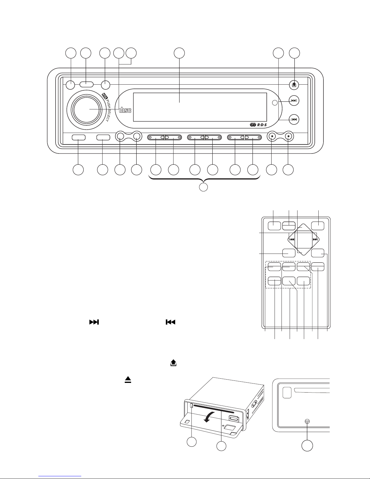
LOCATIONS OF CONTROLS
1. POWER ON/OFF (PWR)
2.
FUNCTION SELECT BUTTON: BASS/TREBLE/BALANCE/
FADER / TA SEEK/MASK DPI/RETUNE L/S /AUDIO DSP/
LOUDNESS/ESP/BEEP/SEEK/STEREO/LOCAL/VOL LAST
3. VOL UP/VOL DOWN FOR BASS/TREBLE/BALANCE/FADER
4. PRESET STATIONS (1,2,3,4,5,6)
5. ‘AF’ function (ALTERNATIVE FREQUENCIES)
6. ‘TA’ function (TRAFFIC ANNOUNCEMENT)
7. ‘PTY’ function (PROGRAM TYPE)
8. DISPLAY BUTTON (DISP)
9. MODE BUTTON (MD)
10. BAND/SUBWOOFER BUTTON (BAND/SUB)
11. AUTOMATIC OR MANUAL TUNING
(FREQ UP OR FREQ DOWN )/
CD TRACK/SEARCH BUTTON
12. AUTO SEEK SEARCH TUNING (A/PS)
13. ‘SCAN’ AUTOMATIC TUNING CONTROL (SCN)
14. LCD DISPLAY
15. OPEN PANEL RELEASE BUTTON ( )
16. CD SLOT
17. CD EJECT BUTTON ( )
18. PAUSE BUTTON
19. INTRO BUTTON (Preview all Tracks)
20. REPEAT BUTTON
21. RANDOM BUTTON
22, 23. + 10 TRACK SEARCH DOWN/UP
24. RESET BUTTON
COMPACT
DIGITAL AUDI O
PWR
BAND
MD
DISP PTY
TA
AF
1 PAU 2 INT 3 RPT 4 RDM 5 6
SCN A/PS
TUNE/
TRACK
REL
SUB
1 10 9 1511142 3
8 7 6 5 13 1218 19 20 21 22 23
4
(1-6)
COMPACT
DIGITAL AUDI O
PWR
BAND
MD
DISP PTY
TA
AF
1 PAU 2 INT 3 RPT 4 RDM 5 6
SCN A/PS
TUNE/
TRACK
REL
SUB
1
11
10
4
2 93
23
2022
21
18 19
12
8
(1-6)
POWER
2
INT3RPT MP3
1
PAUSE
MODE
DISP
5 64
RDM
AS/PS
BAND
SEL
ENTER
VOL
VOL
TUNE/SEEK
E-2
INSTALLATION
PRECAUTIONS
• Choose the mounting location carefully so that the unit will not interfere with the normal
driving functions of the driver.
• Avoid installing the unit where it would be subject to high temperatures, such as from direct
sunlight or hot air from the heater, or where it would be subject to dust, dirt or excessive
vibration.
• Use only the supplied mounting hardware for a safe and secure installation.
• Be sure to remove the front panel before installing the unit.
Mounting angle adjustment
Adjust the mounting angle to less than 20°.
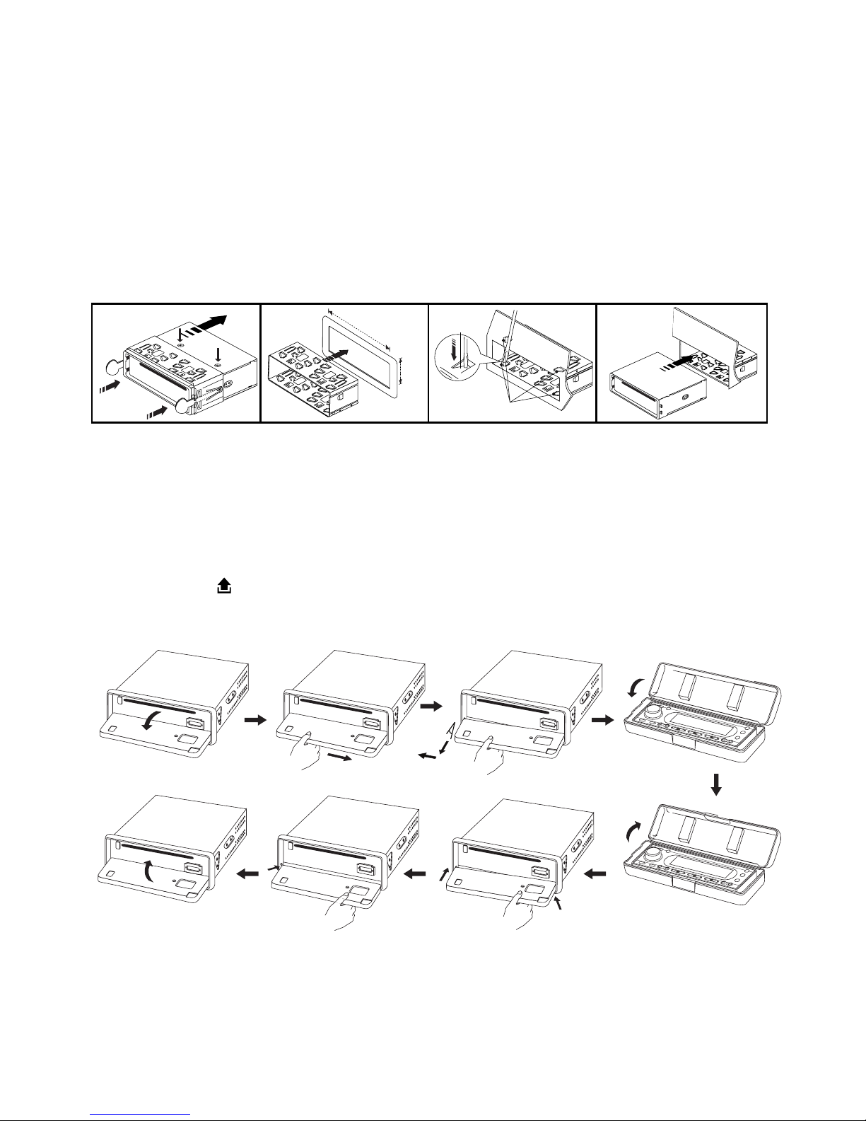
MOUNTING EXAMPLE
Installation in the dashboard
Note: Keep the release key in a safe place as you may need it in the future to remove the
unit from the car.
Detaching and attaching the front panel
The front panel of this unit can be detached in order to prevent the unit from being stolen.
FOLDING DOWN AND DETACHING/ATTACHING THE FRONT PANEL
Before detaching the front panel, be sure to press the PWR button (1) OFF first.
Then press the button (15), let the Front Panel arrive in horizontal position and detach
the panel by pulling it towards you as illustrated.
Notes:
• Do not press the front panel hard against the unit when attaching it. It can be easily attached by pressing it lightly against the unit.
• When you carry the front panel with you, put it in the supplied front panel case.
• Do not press hard or give excessive pressure to the display window of the front panel
when attaching it to the unit.
2
182mm
53mm
3
4
TAP
1
2
1
3
Bend these
claws, if necessary
Release screw and
bracket
1
2
< 10°
E-3
10
7
1
2
3
4
4
4
5
5
6
6
8
9
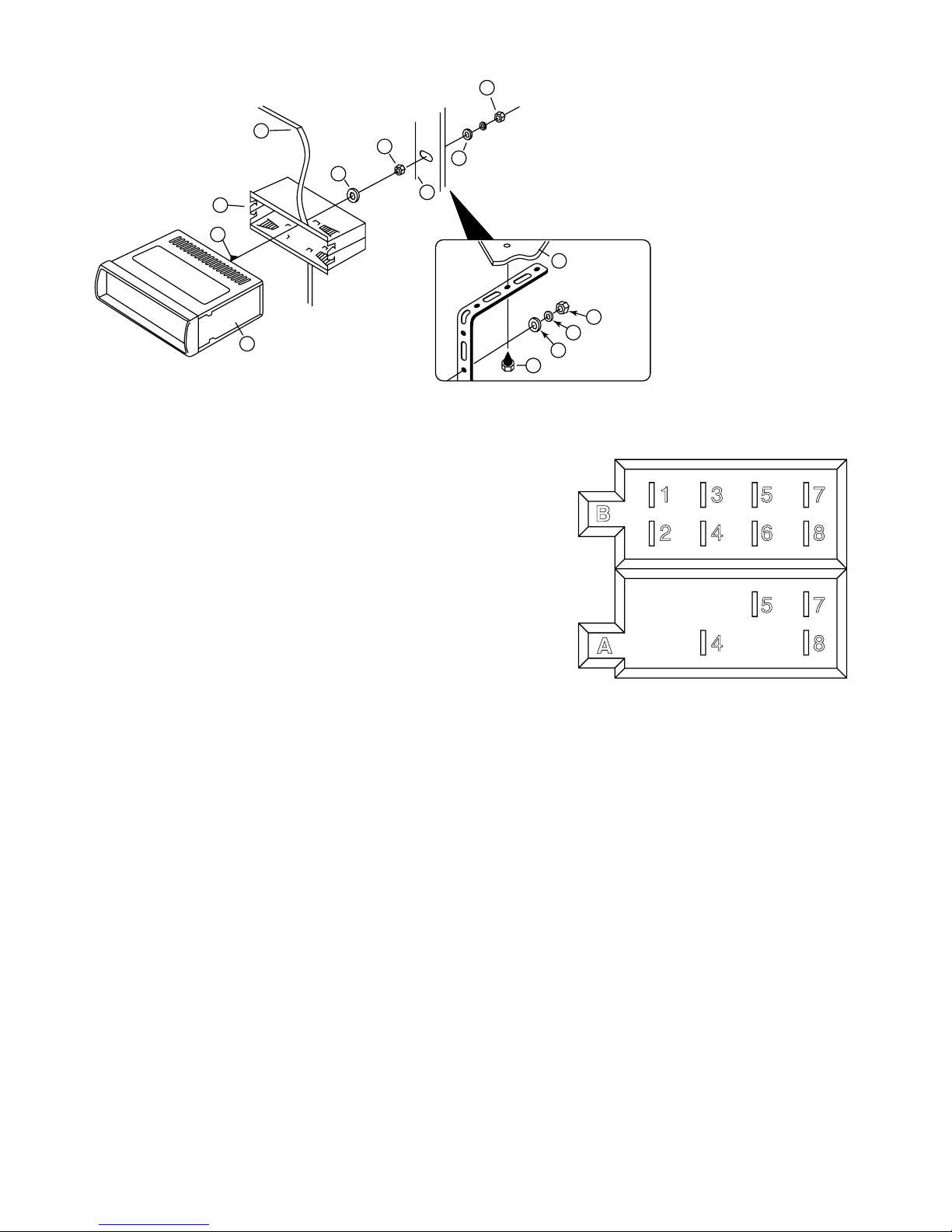
TO SUPPORT THE UNIT
ISO CONNECTOR
RCA Jack Line Out (Front): Red (right) White (left)
RCA Jack Line Out (Rear): Red (right) White (left)
RCA Jack Line In: Red (right) White (left)
Subwoofer: Orange
CONNECTOR A
1.
2.
3.
4. MEMORY +12V
5. AUTO ANTENNA OUTPUT
6.
7. +12V (TO IGNITION KEY)
8. GROUND
Note: (connector A no. 7) must be connected by car ignition key in order to avoid that car
battery being drained when the car will be not used for long period.
CONNECTOR B
1. REAR RIGHT SPEAKER (+)
2. REAR RIGHT SPEAKER (-)
3. FRONT RIGHT SPEAKER (+)
4. FRONT RIGHT SPEAKER (-)
5. FRONT LEFT SPEAKER (+)
6. FRONT LEFT SPEAKER (-)
7. REAR LEFT SPEAKER (+)
8. REAR LEFT SPEAKER (-)
Maintenance
FUSE REPLACEMENT
If the fuse blows, check the power connection and replace the fuse. If the fuse blows again
after the replacement, there may be an internal malfunction. In this case, consult your nearest repair center.
Warning
Use the specified amperage fuse for each lead. Use of a higher amperage fuse may cause
serious damage.
1. UNIT
2. RELEASE CASE
3. DASH BOARD
4. HEX NUT
5. LOCK WASHER
6. PLAIN WASHER
7. CAR BODY
8. REAR SUPPORT STRAP
9. TAPPING SCREW
10. M5 X 15 HEX BOLT
Dashboard
B
1 3 5 7
2 4 6 8
5 7
4 8
A
 Loading...