

Page 1
Mutable Instruments | Warps
Evolved from the oscillator mixing section of Mutable Instruments’ desktop hybrid synths, Warps is
designed to blend and combine two audio signals. A variety of cross-modulation methods - some of them
emulating classic analog circuits, some of them purely digital - are provided by the module. With Warps,
the cross-modulated sound can be sculpted with control voltages along 4 dimensions: by controlling the
amplitude and distorting the input signals, by smoothly scanning through the collection of modulation
algorithms, and by adjusting a timbre parameter controlling the brightness/harshness of the modulated
signal.
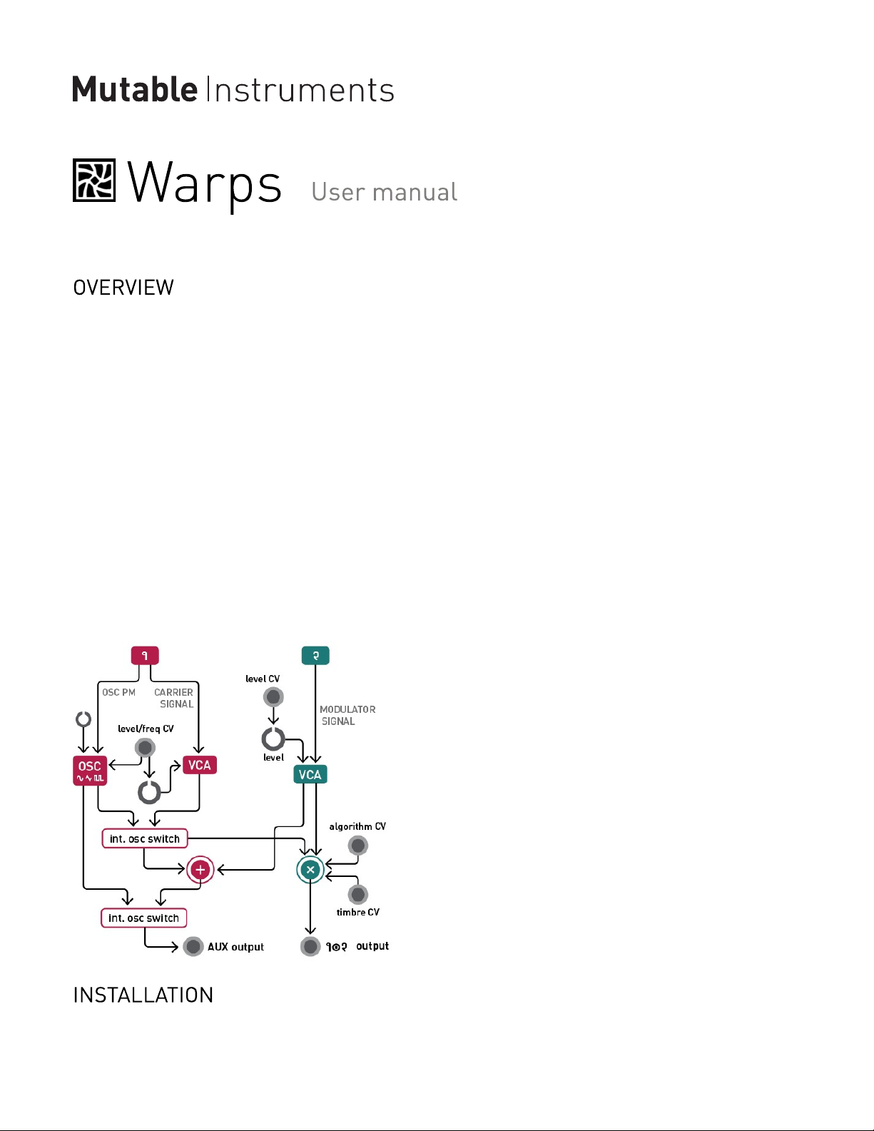
Most cross-modulation algorithms provided in Warps make the distinction between a carrier signal and a
modulator signal: the carrier signal will be filtered or modulated to acquire some of the characteristics of
the modulator signal. However, some other algorithms emulate symmetrical circuits and do not make such
a distinction (the underlying mathematical operation is commutative).
Since many classic cross-modulation effects work best when the carrier is a simple waveform - for
example, a sine wave for ring-modulation or a buzzing waveform simulating glottal pulses for vocoding Warps includes a digital oscillator offering a handful of classic waveforms. This internal oscillator tracks
V/Oct and will replace the carrier audio input - freeing up one oscillator in your system for other duties!
Warps is designed for Eurorack synthesizer systems and occupies 10 HP of space. It requires a -12V /
+12V supply (2x5 connector), consuming 5mA from the -12V rail and 110mA from the +12V rail. The red
1 of 6
Page 2
Mutable Instruments | Warps
stripe of the ribbon cable must be oriented on the same side as the “Red stripe” marking on the printed
circuit board.
This device complies with part 15 of the FCC Rules. Operation is subject to the following
two conditions: (1) This device may not cause harmful interference, and (2) this device must
accept any interference received, including interference that may cause undesired
operation.
This device meets the requirements of the following standards: EN55032, EN55103-2,
EN61000-3-2, EN61000-3-3, EN62311.
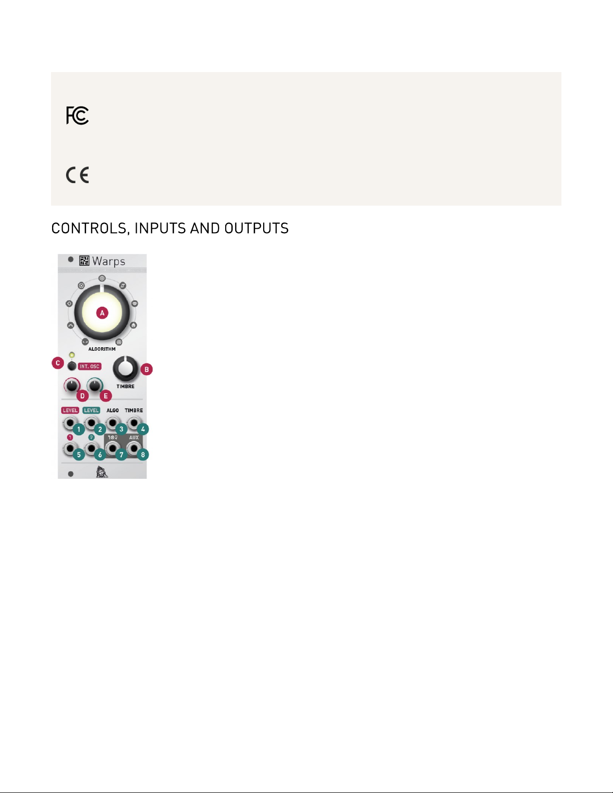
A. Modulation algorithm. This knob selects which signal processing operation is performed on the carrier
and modulator. The algorithms are described in further details in the next section.
B. Modulation timbre. This knob controls the intensity of the high harmonics created by cross-modulation
- or provides another dimension of tone control for some algorithms.
C. Internal oscillator state. This button enables the internal oscillator and selects its waveform. The color
of the LED depends on the oscillator waveform - when the LED is off, the internal oscillator is disabled and
an external signal is used as a carrier.
D. External carrier amplitude or internal oscillator frequency. When an external carrier is used (that is
to say, when the internal oscillator is switched off), this knob controls the amplitude of the carrier, or the
amount of amplitude modulation from the channel 1 LEVEL CV input. When the internal oscillator is
active, this knob controls its frequency.
E. Modulator amplitude. This knob controls the amplitude of the modulator, or the amount of amplitude
modulation from the channel 2 LEVEL CV input. Note that gains above 1.0 can be applied, for a warm
overdrive effect!
1. External carrier amplitude or internal oscillator frequency CV input. When the internal oscillator is
switched off, this CV input controls the gain of the carrier input. When the internal oscillator is enabled, it
2 of 6
Page 3

Mutable Instruments | Warps
acts instead as a V/Oct control for the oscillator frequency.
2. Modulator amplitude CV input. This CV input controls the gain of the modulator input. Just like its
carrier counterpart, it is internally normalized to a constant +5V source when no patch cable is plugged in.
When a signal is patched into this input, the amount of CV modulation is controlled by the Modulator
amplitude knob (E).
3. Algorithm CV input. The CV on this input is added to the position of the Modulation algorithm knob
(A).
4. Timbre CV input. The CV on this input is added to the position of the Modulation timbre knob (B).
5. 6. Carrier (1) and modulator (2) audio inputs. Warps expects modular-level signals (typically 10Vpp,
up to 20Vpp).
7. Modulator output (1x2). This is the main audio output.
8. Auxiliary output. This output carries, when the internal oscillator is disabled, the sum of the carrier and
the modulator, post VCA. Otherwise, it carries the raw waveform from the internal oscillator.
The carrier and modulator are crossfaded into each other, using a constant-power law. TIMBRE controls
the crossfading position - both signals are equally mixed at 12 o’clock.
The carrier and modulator are summed, a tiny bit of cross-modulation product is added to spice things up,
and the resulting signal is sent to a wavefolder the amount of which is controlled by TIMBRE.
The carrier and modulator are crudely multiplied, using a digital model of a diode ring-modulator. TIMBRE
post-processes the resulting signal with a variable amount of gain (and emulated diode clipping).
A gentler version of the previous algorithm which uses a proper multiplication operation in the digital
domain, which will sound more similar to all the AD633-based analog ring-modulators out there! TIMBRE
post-processes the signal with a gain boost and soft-clipping.
Both carrier and modulator are converted to 16-bit integers, and the two resulting numbers are XOR’ed bit
by bit. TIMBRE controls which bits are XOR’ed together.
A handful of signals are synthesized through comparison operations (“replace the negative portion of the
carrier’s signal by the modulator”, “if the absolute value of the carrier is greater than the absolute value of
the modulator, output the modulator else the carrier”…). TIMBRE morphs through these signals (some of
which having an octave pedal flavor).
3 of 6
Page 4

Mutable Instruments | Warps
A classic implementation of an analog vocoder, with a bank of 20 analysis and 20 synthesis third-octave
48dB filters. The modulator sub-band signals are processed by envelope followers from which are derived
the gains of each of the carrier sub-band signals. TIMBRE warps the connections between the
modulator’s envelope followers and the carrier ’s gain elements - effectively shifting up or down the
formants extracted from the modulator signal.
As the ALGORITHM knob is turned clockwise, the release time of the envelope followers is increased.
By turning the knob fully clockwise, the modulator signal is frozen. The carrier is filtered by whichever
formants were present in the modulator signal before the knob reached this position.
Press the INT. OSC button (C) to enable the internal oscillator or select its waveform. Because cross-
modulation algorithms work best with harmonically simple signals, while vocoders work better with
harmonically rich signals, the available waveforms are different: sine, triangle and sawtooth for the former,
and sawtooth, pulse and low-pass filtered noise for the later.
Some of the inputs, outputs or controls operate differently when the internal oscillator is enabled:
The LEVEL knob (D) and CV input (1) control the internal oscillator frequency.
The Carrier audio input (5) phase-modulates the internal oscillator, or feeds an external source of noise into
the low-pass filter.
The AUX output (8) contains the signal generated by the internal oscillator.
The module is factory-calibrated using precision voltage sources. Follow this procedure only if you
want to compensate for inaccuracies in your CV sources, or if your module has lost its calibration
settings following a fault or the installation of alternative firmware.
To calibrate the unit:
Disconnect all CV inputs.1.
Hold the INT. OSC button for five seconds until the ALGORITHM knob blinks in turquoise and the oscillator
2.
state LED blinks in yellow.
Connect a patch cable to the LEVEL 2 CV input. Leave the other end of the cable unplugged.3.
4 of 6
Page 5

Mutable Instruments | Warps
Connect the CV output of a well-calibrated keyboard interface or MIDI-CV converter to the LEVEL 1 CV input.4.
Play a C2 note, or send a 1V voltage from your CV source.5.
Press the INT. OSC button. The ALGORITHM knob blinks in fuchsia.6.
Play a C4 note, or send a 3V voltage from your CV source.7.
Press the INT. OSC button.8.
Calibration is done!9.
Unplug all CV inputs/outputs from the module. Connect the output of your audio interface/sound card to
the Carrier audio input (5) input. Power on your modular system with the INT. OSC (C) push-button
pressed. The INT. OSC LED will blink in orange.
Make sure that no additional sound (such as email notification sounds, background music etc.) from your
computer will be played during the procedure. Make sure that your speakers/monitors are not connected
to your audio interface - the noises emitted during the procedure are aggressive and can harm your
hearing. On non-studio audio equipment (for example the line output from a desktop computer), you might
have to turn up the volume to the maximum.
When you are all set, play the firmware update file into the module. While the module receives data, the
color of the ALGORITHM knob will reflect signal level - green or yellow is fine, red is too high! You can
use the Carrier amplitude (D) knob to adjust the input gain.
In case the signal level is too weak, the LEDs will blink in red. Press the INT. OSC button and retry with a
correct gain. If this does not help, please retry the procedure from another computer/audio interface, and
make sure that no piece of equipment (equalizer, FX processor) is inserted in the signal chain.
This product is covered by Mutable Instruments’ warranty, for one year following the date of manufacture.
This warranty covers any defect in the manufacturing of this product. This warranty does not cover any
damage or malfunction caused by incorrect use - such as, but not limited to, power cables connected
backwards, excessive voltage levels, or exposure to extreme temperature or moisture levels.
The warranty covers replacement or repair, as decided by Mutable Instruments. Please contact our
customer service (support@mutable-instruments.net) for a return authorization before sending the
module. The cost of sending a module back for servicing is paid for by the customer.
Mutable Instruments encourages modding and hacking, but we will not service modified units or provide
any assistance in the realization of mods.
5 of 6
Page 6

Mutable Instruments | Warps
6 of 6
 Loading...