

Page 1

About Veils
VCAs are the cornerstones of modular patches: shaping the amplitude or timbre of a tone with an envelope,
animating a mixture of several oscillators, controlling
the amount of fi lter modulation with a random source
or a touch controller, applying an envelope on the linear
FM signal hitting an oscillator... are all possible uses of
these super versatile building blocks.
Veils provides four VCAs with an adjustable response
curve. Veils’ outputs are daisy-chained, allowing
adjacent groups of 2, 3, or all 4 channels, to be mixed
together.
Veils
Veils requires a -12V / +12V power supply (2x5 pin
connector). The red stripe of the ribbon cable (-12V side)
must be oriented on the same side as the “Red stripe”
marking on the board. The module draws 50mA from the
-12V rail and 50mA from the +12V rail. Current consumption can reach 70mA on either rail depending on
the color and brightness of the LEDs.
Online manual and help
The full manual can be found online at
mutable-instruments.net/modules/veils/manual
For help and discussions, head to
mutable-instruments.net/forum
Please refer to the online manual for detailed information regarding compliance with EMC directives
Quad VCA
Page 2
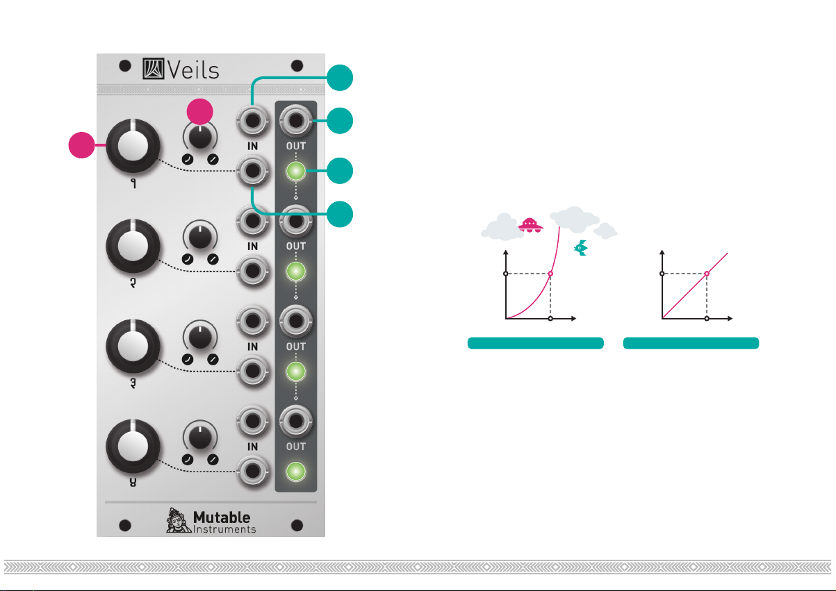
A. Gain CV amount. Amount of gain (amplitude) modu-
1
B
2
A
lation from the CV input (4), or direct gain control when
no cable is patched in the CV input. When this knob is
turned fully clockwise, a CV of +5V yields a gain of 1, and
a CV above +5V might cause distortion.
B. Response curve. Continuously variable between
exponential and linear. Because the exponential function
3
grows rapidly, very high gains can be achieved with an
exponential response curve. Beware of clipping!
4
Gain
1
CV
5V
EXPONENTIAL LINEAR
Gain
1
CV
5V
1. DC-coupled signal input. Accepts audio or CV signals.
2. Signal output. When no patch cable is plugged into an
output, the signal from this channel is routed to the next
channel. For example, when no patch cable is patched
into output 1, output 2 will contain the sum of channel 2
and channel 1. If nothing is patched into outputs 1, 2 and
3, output 4 will contain the sum of all four channels.
3. Indicator LED. Brightness represents signal level, and
color represents signal polarity (green = positive).
4. Gain CV input. Normalized to a constant +8V.
 Loading...