

Page 1
Envelope generator
In this mode, EXCITE behaves like a trigger input, triggering an envelope generator. This envelope is internally
routed to the VCA and the VCF.
SHAPE controls the envelope attack and decay time.
attack
increases
decay
increases
attack and decay
decrease
The envelope curve depends on the amplitude (height)
and duration (width) of the trigger pulse.
MOD controls the range of filter modulation.
Vactrol emulation
In this mode, the VCA gain and VCF frequency are
controlled by a moody Vactrol low-pass gate emulation.
EXCITE is the amplitude/brightness CV input.
SHAPE controls the Vactrol on/off response times, and
MOD the amount of damping - using the same control
scheme as for the envelope mode.
Signal follower
The EXCITE signal is analyzed to extract its amplitude
and cutoff envelopes. The IN signal is then amplified and
filtered with these envelopes.
SHAPE controls the attack and release time of the detector. MOD controls the range of filter modulation.
Compressor
In this mode, the VCF is disabled and the VCA is used to
compress the dynamic range of the IN signal. Optimal
results are obtained when the VCA response curve is set
to exponential. EXCITE is a sidechain input – for normal
operation, leave it unconnected.
SHAPE controls the compression threshold, from -30dB
to 0dB. MOD controls both the compression ratio and
make-up gain:
Tame loud parts
The compressor has a fast detector (0.2ms attack time,
150ms release time) and a hard knee.
Boost quiet parts
Tips and tricks
Heck, no input?
In Vactrol mode, leave IN unconnected, send a CV to
EXCITE and get a smoothed CV on OUT.
In envelope or Vactrol mode, leave IN unconnected, send
a positive CV to LEVEL MOD. Use the linear/exponential
control to waveshape it, and the MOD control to filter it.
To get an envelope CV out of the envelope follower, leave
IN unconnected.
In envelope (or Vactrol) mode, patch a velocity CV to IN
and send a trigger (or gate) to EXCITE, to get a velocity-scaled envelope on OUT. Use MOD to control envelope
smoothness.
Offsets and boosts
In Vactrol mode, leave LEVEL unconnected and use
LEVEL MOD to add a gain offset, pushing the VCA into
saturation.
Leave EXCITE and LEVEL unconnected. Set the VCA
response to exponential. Use LEVEL MOD to drastically
boost the IN signal until saturation is reached. Tame it
back by adjusting cutoff with MOD - that’s why we put
the VCF after the VCA!
Combos
Use channel 1 to shape a CV and channel 2 to apply it to
an audio signal. Use channel 1 to filter/distort/boost an
audio signal and channel 2 to compress it.
Streams
Dual dynamics gate
Page 2
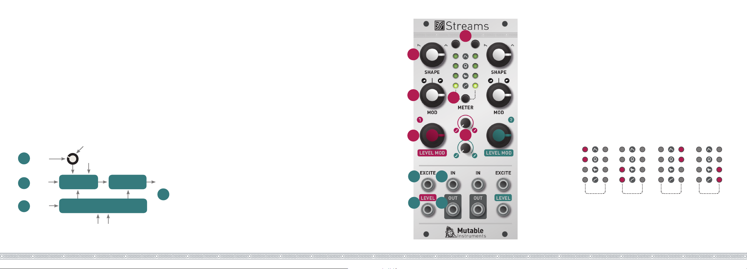
About Streams
Streams is a dual-channel toolbox for shaping the amplitude and brightness of audio signals or CVs.
Each channel consists of a VCA and a VCF. The control
voltages for these two analog circuits are digitally generated, by “reacting to,” “following” or “listening to” a
multi-purpose input called EXCITE. There are 4 different
ways in which the module can adjust its gain and cutoff
frequency in response to the excitation signal: envelope
generation, Vactrol emulation, signal following, and
dynamic compression.
Additionally, the VCA gain can be directly controlled by a
CV - independently of the digital control path.
Level mod attenuator
Level
3
CV in
Signal
2
input
Excite
1
input
Exp/lin control
analog VCA analog VCF
digital CV generator
Shape control and modulation amount
Output
4
Installation
Streams requires a -12V / +12V power supply (2x5 pin
connector). The red stripe of the ribbon cable (-12V side)
must be oriented on the same side as the “Red stripe”
marking on the board. The module draws 30mA from the
-12V rail and 100mA from the +12V rail.
Online manual and help
The full manual can be found online at
mutable-instruments.net/modules/streams/manual
For help and discussions, head to
mutable-instruments.net/forum
Front panel
Inputs and Outputs
1. Multi-purpose excitation input.
2. DC-coupled signal input, normalized to a constant
+5V offset.
3. Unipolar VCA CV input, normalized to a constant +8V
offset. Unity gain is achieved with a voltage equal to +5V.
4. DC-coupled signal output.
Controls
D
A
B
C
1
3
F
E
2
4
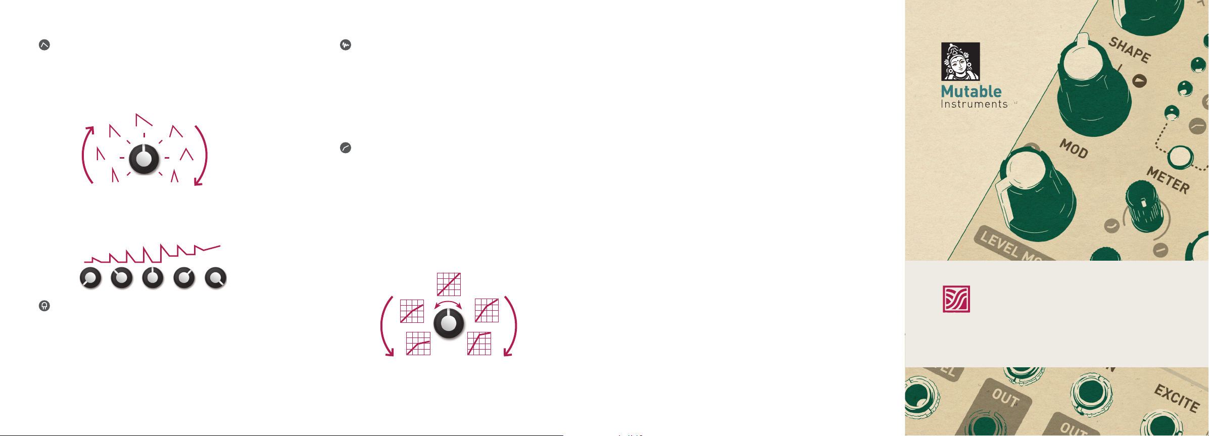
A. B. Digital CV generator parameters.
SHAPE controls how fast the module adjusts amplitude
and brightness in reaction to the excitation signal. MOD
controls the amount and range of VCF modulation.
These knobs also control compression threshold and
ratio when the dynamic compressor mode is used. More
details are provided in the next pages.
C. Level CV input attenuator.
D. Function selector. Cycles through the four functions.
E. VCA response curve, from exponential to linear.
F. Metering button. Press to display the bargraph. Press
again to select which signal is to be monitored.
EXCITE
METER
Audio signals are metered with a dB scale of 6dB/LED.
Slow CVs are displayed with a linear scale of 2V/LED the LED color indicates signal polarity.
LEVEL
METER
IN
METER
VCA OUT
METER
 Loading...