

Page 1
Mutable Instruments | Stages
Stages requires a -12V/+12V power supply (2x5 pin connector). The red stripe of the ribbon cable (-12V
side) must be oriented on the same side as the “Red stripe” marking on the module and on your power
distribution board. The module draws 80mA from the +12V rail, and 20mA from the -12V rail.
This device complies with part 15 of the FCC Rules. Operation is subject to the following
two conditions: (1) This device may not cause harmful interference, and (2) this device must
accept any interference received, including interference that may cause undesired
operation.
This device meets the requirements of the following standards: EN55032, EN55103-2,
EN61000-3-2, EN61000-3-3, EN62311.
Use the 3-pin cables provided with the modules to daisy-chain up to six modules together. Make sure your
Eurorack system is powered off whenever you connect or disconnect units from the chain. Once several
adjacent modules are linked, they behave collectively like a single Stages module which would have a
larger number of segments.
Whether Stages behaves like six independent decay envelopes, or a single 6-segment envelope
generator, or something in-between, depends on which of its GATE inputs are patched.
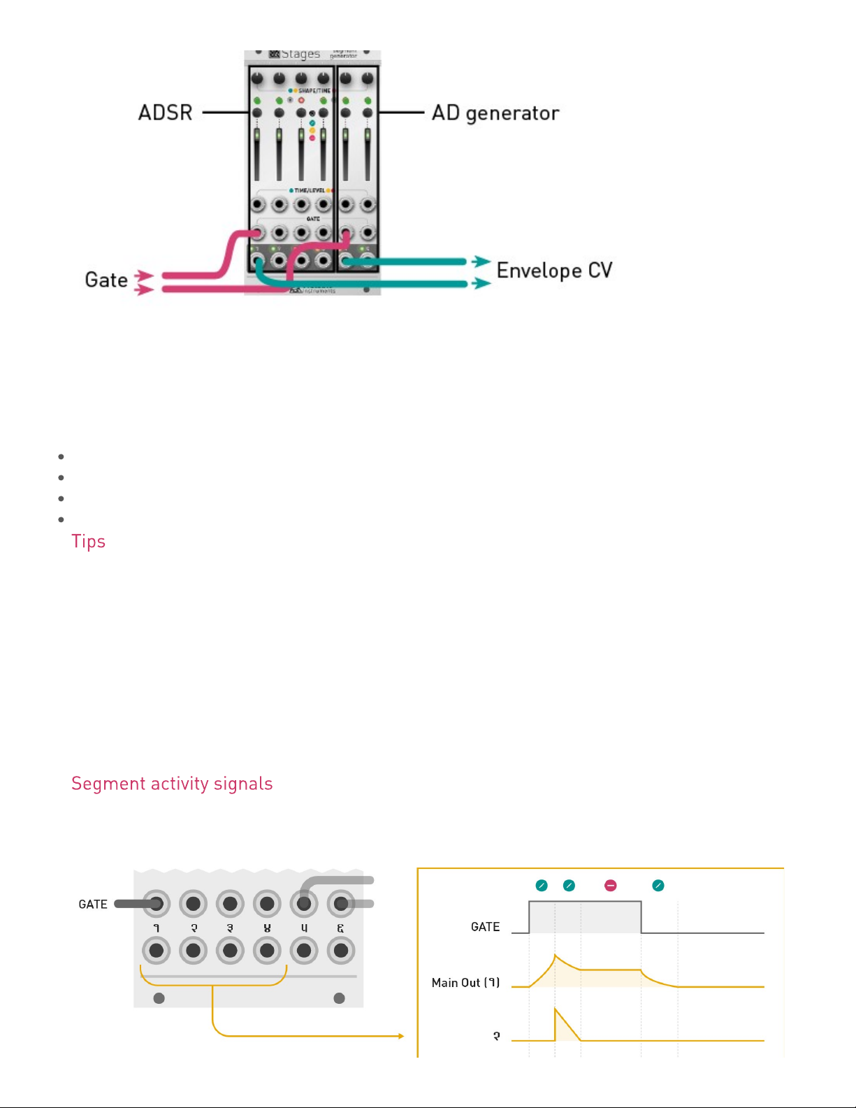
Inserting a jack in a GATE input marks the beginning of a group of segments. All unpatched segments at
its right become part of this group. The first output of a group generates the envelope signal itself. The
following outputs generate segment activity signals – ramps going from 8V to 0V whenever the
corresponding segment is active.
In the illustration below, GATE inputs 1 and 5 are patched. The module behaves as:
A 4-segment envelope generator, configured by segments 1 to 4, generating its envelope signal on output
1, and segment activity signals on outputs 2, 3, and 4.
An independent 2-segment envelope generator, configured by segments 5 and 6, generating the envelope
signal on output 5, and an end-of-attack signal on output 6.
1 of 8
Page 2
Mutable Instruments | Stages
What happens if only GATE input 5 is patched? Segments 5 and 6 act as a 2-segment envelope
generator; and segments 1, 2, 3 and 4 are four independent free-running generators. Even if these four
independent generators do not receive gates or triggers, looping can be enabled for them, turning them,
for example, into four LFOs.
A few more examples:
No GATE input is patched: Segments 1 to 6 are all independent, free running segments.
GATE inputs 1, 3 and 5 are patched: Three independent 2-segment envelopes.
GATE inputs 1, 5 and 6 are patched: One 4-segment envelope and two single-segment envelopes.
All GATE inputs are patched: Six independent single-segment envelopes.
When building a patch, patch from right to left. For example, starting from a blank page, if you need an AD
envelope, patch your gate signal into the GATE input of segment 5 – leaving you segments 1 to 4 for
LFOs, utility functions… or other envelopes.
Self-patching is rewarding with Stages! For example, configure segment 1 as an independent, free
running LFO to modulate other segments.
It is sometimes handy to use “dummy” patch cables (or just a jack with no cable attached to it). For
example, if you have created a 6-segment envelope spanning segments 1 to 6, and if you want to change
its shape to a classic 4-segment ADSR, patch a dummy cable into input 5 to “detach” segments 5 and 6
from the chain starting at segment 1.
The illustration below shows the signals produced on outputs 1 to 4, assuming the module is used as a
4-segment ADSR (segments 5 and 6 are used for other duties).
2 of 8
Page 3
Mutable Instruments | Stages
Press the button [B] to modify the action performed by a segment.
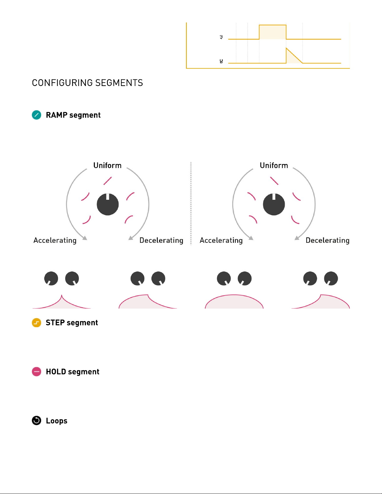
The output smoothly ramps from one voltage to another, then the next segment is activated. The
ramping time is controlled by the slider [C] and the CV input [1]. The shape of the curve is controlled by
the potentiometer [A], from accelerating, through uniform, to decelerating.
The following illustration shows how these shapes can be combined for an AD envelope:
The output glides to the target voltage, stays at this voltage until a trigger is received, and then the next
segment is activated. Just like a step in a sequence! The voltage (from 0V to 8V) is controlled by the slider
[C] and the CV input [1]. The glide amount is set by the potentiometer [A].
The output stays at the same voltage for an adjustable duration, then the next segment is activated.
The voltage (from 0V to 8V) is controlled by the slider [C] and the CV input [1]. The duration of the
segment is set by the potentiometer [A].
To make a segment loop on itself, hold the button [B] for one second. The LED now blinks to indicate the
loop.
To create a loop spanning several segments within the same group, simultaneously press the button [B] of
3 of 8
Page 4

Mutable Instruments | Stages
the first and last segments in the loop. The corresponding LEDs will blink with a “ping pong” pattern.
To disable a loop, hold the button [B] of either the start or end segment of the loop.
Important: a loop can only span segments belonging to the same group. And what defines groups? The
presence of jacks in the GATE input! For example, if you want to use Stages as 3 self-looping AD
envelopes, you’ll need to insert “dummy” patch cables into the inputs #1, #3, #5 to explicitly tell the
module that segments 1 and 2, 3 and 4, 5 and 6 are grouped together.
The first RAMP segment ramps up to 8V, starting from whatever level the output currently stays at.1.
The last RAMP segment ramps down to 0V.2.
The level of a HOLD or STEP segment defines the start (end) level of the RAMP segment that follows
3.
(precedes) it. For example, in the preceding illustration, the end level of segment 3, and the start level of
segment 5 are both set by the level of the HOLD segment 4.
If the end level of a RAMP segment cannot be determined by rules 1, 2 or 3, this level is explicitly set by the
4.
potentiometer [A]. For example, in the preceding illustration, the end level of segments 2 and 5 are set by
their potentiometer.
If a LOOP is defined, the loop is played while the GATE signal is high. Once the GATE goes low, the
5.
envelope proceeds with the segment(s) that follow the loop end point. If the loop end is the last segment,
there’s no escape from the loop, and the loop keeps going on forever.
If the envelope contains a STEP segment, it follows its course normally until it gets trapped at the first STEP
6.
segment. It will stay at this segment until the next trigger is received. When this trigger is received, it will then
proceed to the next segment… until the last segment or another STEP segment is reached. If an envelope
contains a STEP segment inside a loop, there is no way of escaping this loop!
As a direct consequence of the segment rules (with a few tweaks!), an independent, isolated segment can
perform a variety of interesting functions.
A non-looping single RAMP segment is a Decay envelope generator, with its decay time adjusted by the
4 of 8
Page 5

Mutable Instruments | Stages
slider [C] and CV input [1], and its curve adjusted by the potentiometer [A].
A looping single RAMP segment behaves like an LFO, the waveform of which is controlled by the
potentiometer [A]. Instead of the simple logarithmic/linear/exponential curves, a more sensible selection of
waveforms is provided: variable slope saw/triangle, sine, variable slope trapezoid. If the GATE input is not
patched, the LFO frequency is set by the slider [C] and CV input [1]. If the GATE input is patched, the
LFO follows the tempo set by the GATE signal, with a clock division/multiplication factor from 1⁄4 to 4 set
by the slider.
A single STEP segment works as a sample and hold: at every rising edge of the GATE, it records and
holds the voltage set by the slider [C] and CV input [1]. Use the potentiometer [A] to change the glide
rate.
If nothing is patched in the GATE input, the slider and CV input will be continuously tracked, but will still be
subject to the glide effect.
If the GATE input is patched, an independent HOLD segment behaves as a pulse generator. The slider
[C] and CV input [1] set the pulse voltage, while the potentiometer [A] controls the pulse duration. If
looping is enabled, the pulse lasts for as long as the gate signal is high.
If the GATE input is not patched, the segment behaves as a CV delay. The voltage set by the slider [C]
and CV input [1] is sent to the output with a delay set by the potentiometer [A]. Even without an external
CV patched into the input, you can use this as a slider-controlled CV source with delayed action.
Many envelope shapes can be programmed with Stages. The arrows denote the loop region.
5 of 8
Page 6

Mutable Instruments | Stages
Classic ADSR envelope.
Classic ADSR envelope with an adjustable pre-delay and initial level.
ADSR envelope with a non-zero rest level, adjusted by the last HOLD segment. The CV output for the last
segment can be used as an end-of-release trigger.
AHDSR envelope – the hold level and time are controlled by the second segment.
AD1D2SR envelope with a break point between the apex and sustain. The potentiometer [A] of the
second segment controls the voltage at this break point.
An even more complex AD1D2SR1R2 envelope, with break points at both the decay and the release
stages.
AD envelope.
AR envelope. The sustain level is set by the HOLD segment.
A trapezoid LFO, with the minimum and maximum level and plateau durations set by the segment 2 and 4;
and the time and curve of the ramp set by the segment 1 and 3.
A 5-note sequence. Modify the loop points to loop on a subset of this sequence. Patch external voltages
6 of 8
Page 7

Mutable Instruments | Stages
into the CV inputs of each stage, to turn this into a 5-stage sequential switch.
A 3-note sequence, with adjustable linear glide between each step.
This product is covered by Mutable Instruments’ warranty, for one year following the date of manufacture.
This warranty covers any defect in the manufacturing of this product. This warranty does not cover any
damage or malfunction caused by incorrect use - such as, but not limited to, power cables connected
backwards, excessive voltage levels, or exposure to extreme temperature or moisture levels.
The warranty covers replacement or repair, as decided by Mutable Instruments. Please contact our
customer service (support@mutable-instruments.net) for a return authorization before sending the
module. The cost of sending a module back for servicing is paid for by the customer.
Mutable Instruments encourages modding and hacking, but we will not service modified units or provide
any assistance in the realization of mods.
7 of 8
Page 8

Mutable Instruments | Stages
8 of 8
 Loading...