

Page 1
Mutable Instruments | Peaks
Peaks is a two-channel, general-purpose, trigger processor: it translates incoming triggers or gates into
envelopes, synchronized periodic modulations (LFO and tap-LFO), or drum signals. Peaks can also be
directly “played” thanks to its two trigger buttons. Our goal with this module is to give you many different
ways of modulating your patches in as little space as possible!
Peaks is designed for Eurorack synthesizer systems and occupies 8 HP of space. It requires a -12V /
+12V supply (2x5 connector), consuming 2mA from the -12V rail and 60mA from the +12V rail. The red
stripe of the ribbon cable must be oriented on the same side as the “Red stripe” marking on the printed
circuit board.
This device complies with part 15 of the FCC Rules. Operation is subject to the following
two conditions: (1) This device may not cause harmful interference, and (2) this device must
accept any interference received, including interference that may cause undesired
operation.
This device meets the requirements of the following standards: EN55032, EN55103-2,
EN61000-3-2, EN61000-3-3, EN62311.
Peaks is a multi-function module, but the general rule is that cool things happen whenever a trigger is
received. Its four main functions are:
Envelope generator - the gate/trigger input starts and holds the envelope.
LFO - the gate/trigger input resets the waveform cycle.
LFO with tap-tempo synchronization - the gate/trigger input sets the period of the LFO oscillations. Note
that Peaks can “learn” irregular trigger sequences and lock onto them.
Drum generator - the gate/trigger input triggers the drum sound.
Peaks provides two channels of processing - each of them has a gate/trigger input jack, a gate/trigger
button with an output indication LED, and an audio/CV output. Both channels provide the same function the exception being channel 1’s drum generator being a bass drum generator, and channel 2’s drum
generator being a snare drum/hi-hat generator.
Both channels can be “synchronized” (aka twin mode), in that they both share the same front panel
1 of 6
Page 2
Mutable Instruments | Peaks
controls - for example in ADSR envelope mode, the first knob will control both channel 1 and channel 2’s
attack time. This can be used not only to create duophonic patches (for which you actually want both
channels to behave similarly), but also to obtain two synchronized outputs of the same LFO waveform with
different phase shifts…
Another way of controlling the module is the split mode in which the potentiometers 1 and 2 control
channel 1’s settings; and the potentiometers 3 and 4 control channel 2’s settings. This mode only gives
access to the 2 most essential parameters of each function (for example attack and decay time for an
envelope) - the other parameters being set to default “neutral” settings.
Finally, if breaking the one knob per function rule is not a taboo for you, an expert mode allows individual
control of channel 1 and 2.
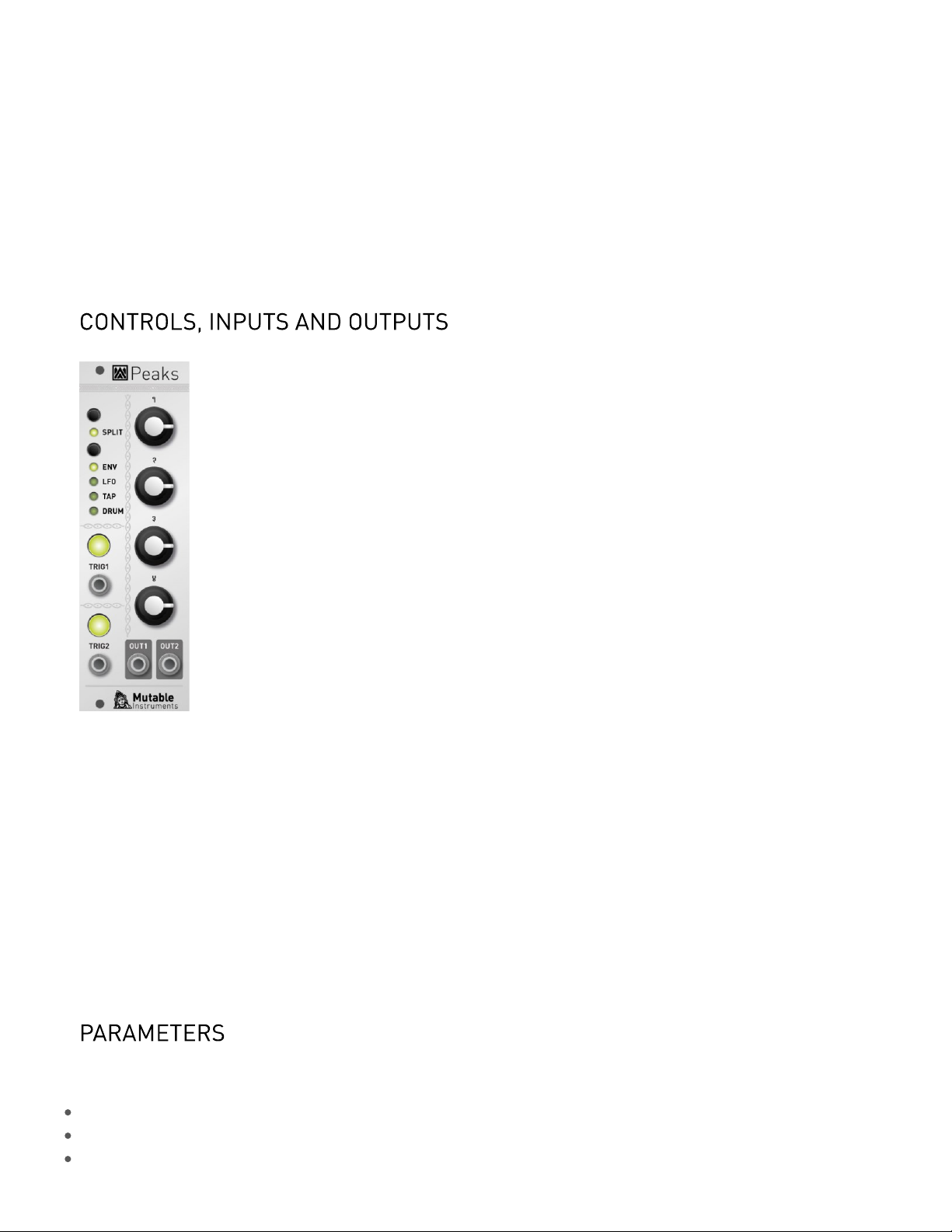
The split button toggles between the twin (LED off) and split (LED on) modes. Hold it for a second to
enter the expert mode. In this mode, the button toggles between channel 1 and 2. Hold it for a second to
get back to normal operation.
The FUNCTION button cycles through the 4 main functions.
The 4 potentiometers modify the settings for the selected function. Please refer to the tables in the next
section.
TRIG 1&2 are channel 1 and 2’s trigger inputs. The trigger threshold is 0.7V. Above each of these inputs is
a switch that can be pressed to generate a trigger signal. The LED built into the switch shows the
variations of the output signal.
Finally, OUT 1&2 are channel 1 and 2’s outputs.
ENV function, twin & expert:
Ch. 1&2 Attack
Ch. 1&2 Decay
Ch. 1&2 Sustain
2 of 6
Page 3

Mutable Instruments | Peaks
Ch. 1&2 Release
ENV function, split: Dual A/D envelope generator
Ch. 1 Attack
Ch. 1 Decay
Ch. 2 Attack
Ch. 2 Decay
LFO function, twin & expert:
Ch. 1&2 Frequency
Ch. 1&2 Waveform (sine, linear slope, square, steps, random)
Ch. 1&2 Waveform variation (wavefolder for sine; ascending/triangle/descending balance for slope, pulse-
width for square, number of steps, and interpolation method)
Ch. 1&2 Phase on restart
LFO function, split:
Ch. 1 Frequency
Ch. 1 Waveform
Ch. 2 Frequency
Ch. 2 Waveform
TAP function, twin & expert:
Ch. 1&2 Amplitude
Ch. 1&2 Waveform
Ch. 1&2 Waveform variation
Ch. 1&2 Phase on restart
TAP function, split:
Ch. 1 Waveform
Ch. 1 Waveform variation
Ch. 2 Waveform
Ch. 2 Waveform variation
DRUM function, twin & expert:
Ch. 1&2 Base frequency
Ch. 1&2 Frequency modulation (“Punch” for BD, “Tone” for SD)
Ch. 1&2 High-frequency content (“Tone” for BD, “Snappy” for SD)
Ch. 1&2 Decay
DRUM function, split: The original 808 sweet spot!
Ch. 1 BD Tone
Ch. 1 BD Decay
Ch. 2 SD Tone
Ch. 2 SD Snappy
3 of 6
Page 4

Mutable Instruments | Peaks
Hold the FUNCTION button for one second (it starts blinking). Peaks now provides four alternative
functions instead of envelope/LFO/tap LFO/drum generation. These functions are:
Mini step-sequencer (4-step in twin mode, 2-step in split mode)
Trigger delay/shaper
Trigger stream randomizer
Digital drum synth
Alternative ADSR function, twin & expert: 4-step minisequencer. Each knob controls a step. Channel 1 is
clocked by TRIG 1 and reset by TRIG 2. Channel 2 is clocked by TRIG 2:
Ch. 1&2 Step 1
Ch. 1&2 Step 2
Ch. 1&2 Step 3
Ch. 1&2 Step 4
Alternative ADSR function, split: Dual 2-step minisequencer. Knobs 1&2 control channel 1’s steps, knobs
3&4 channel 2’s steps. There is no reset, and each channel has its clock.
Ch. 1 Step 1
Ch. 1 Step 2
Ch. 2 Step 1
Ch. 2 Step 2
Alternative LFO function, twin & expert:
Ch. 1&2 Pre-delay
Ch. 1&2 Gate duration
Ch. 1&2 Delay
Ch. 1&2 Number of repeats
Alternative LFO function, split:
Ch. 1 Delay
Ch. 1 Number of repeats
Ch. 2 Delay
Ch. 2 Number of repeats
Alternative TAP function, twin & expert:
Ch. 1&2 Probability that an incoming trigger is processed
Ch. 1&2 Probability that the trigger is regenerated after the delay
Ch. 1&2 Delay time
Ch. 1&2 Jitter
Alternative TAP function, split:
Ch. 1 Acceptance/regeneration probability
Ch. 1 Delay
Ch. 2 Acceptance/regeneration probability
Ch. 2 Delay
4 of 6
Page 5

Mutable Instruments | Peaks
Alternative DRUM function, twin & expert:
Ch. 1&2 frequency
Ch. 1&2 FM intensity
Ch. 1&2 FM and AM envelope decay time (the FM envelope has a shorter decay than the AM envelope, but
the two values are tied to this parameter)
Ch. 1&2 Color. At 12 o’clock, no modification is brought to the oscillator signal. Turn right to increase the
amount of noise (for snares). Turn left to increase the amount of distortion (for 909 style kicks).
Alternative DRUM function, split:
Ch. 1 BD presets morphing
Ch. 1 BD presets variations
Ch. 2 SD presets morphing
Ch. 2 SD presets variations
Connect the output of your audio interface/sound card to the TRIG1 input. Power on your modular system
with Peaks’ TRIG1 button pressed. The split, TRIG1, and TRIG2 LEDs will blink.
Make sure that no additional sound (such as email notification sounds, background music etc.) from your
computer will be played during the procedure. Make sure that your speakers/monitors are not connected
to your audio interface - the noises emitted during the procedure are aggressive and can harm your
hearing. On non-studio audio equipment (for example the line output from a Desktop computer), you might
have to turn up the volume to the maximum.
When you are all set, play the firmware update file into the module. The LEDs show a cyclic pattern and
periodically flash upon receiving a valid block of data. The unit reboots after the last packet has been
received.
In case the signal level is too weak or too high, the procedure will stop and the LEDs will blink
alternatively. Press the TRIG1 button and retry from the start of the update file.
This product is covered by Mutable Instruments’ warranty, for one year following the date of manufacture.
This warranty covers any defect in the manufacturing of this product. This warranty does not cover any
damage or malfunction caused by incorrect use - such as, but not limited to, power cables connected
backwards, excessive voltage levels, or exposure to extreme temperature or moisture levels.
The warranty covers replacement or repair, as decided by Mutable Instruments. Please contact our
customer service (support@mutable-instruments.net) for a return authorization before sending the
module. The cost of sending a module back for servicing is paid for by the customer.
Mutable Instruments encourages modding and hacking, but we will not service modified units or provide
any assistance in the realization of mods.
5 of 6
Page 6

Mutable Instruments | Peaks
6 of 6
 Loading...