

Page 1
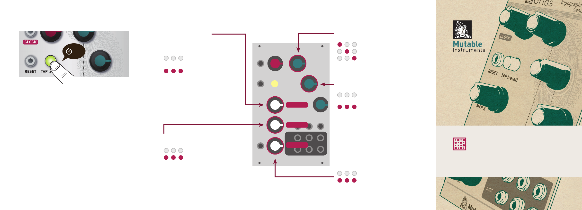
Advanced settings
Advanced settings diagram
1s
Unplug all CV inputs and hold the TAP (reset) button for
a second to adjust Grids' settings. Refer to the diagram
on the next pages for a list of all available settings. The
3 LEDs indicate the value of the setting being modified.
Hold the TAP (reset) button again for a second when you
are done.
Online manual and help
The full manual can be found online at
mutable-instruments.net/modules/grids/manual
For help and discussions, head to
mutable-instruments.net/forum/
Sequencer mode
Grids can also work as a plain
euclidean sequencer.
Grids is yet another
euclidean sequencer
Grids is back to
drumming duties
When euclidean sequencer mode is
enabled, the MAP X / Y / CHAOS knobs
have alternate functions, (STEPS 1-3) as
shown in red on the panel – they control
the duration (number of steps) of the
sequence; while the FILL knobs control
the fill rate.
Trig / Gate output
Outputs are 1 ms triggers
Outputs are gates
STEPS 1
STEPS 2
STEPS 3
Clock resolution
4ppqn
8ppqn
24ppqn
Tap button function
Tap to restart at the beginning
of the sequence
Tap to set the tempo
Outputs configuration
Grids can output either: three individual accent tracks (one per instrument);
or a global accent track, a clock signal
(received on the clock input or internal,
whichever is used), and a reset trigger
sent at the beginning of the pattern.
ACC 1 / ACC 2 / ACC 3
ACC / CLK / RST
Grids
Topographic drum sequencer
Page 2
Installation
Synthesizing
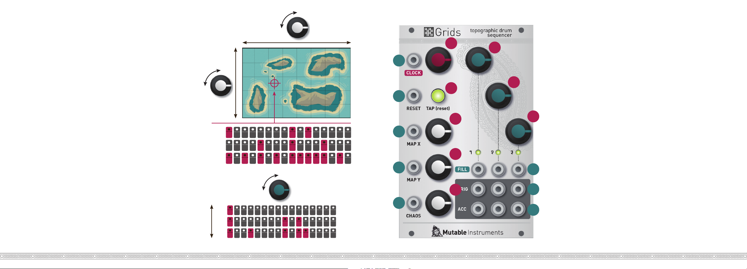
Map X
Front panel
Grids requires a -12V / +12V / +5V power supply (2x8 pin
connector). The ribbon cable connector must be aligned
so that the red stripe of the ribbon cable (-12V) is on the
same side of the module’s power header as the “Red
stripe” marking on the board.
The power consumption is as follows:
-12V: 1mA; +5V: 25mA.
Concept
Grids is a 3-channel, algorithmic, rhythmic pattern generator based on data and models extracted from actual
drum loops. Two steps are involved in the generation of
the drum patterns:
Step 1: Synthesizing a pattern from the drum map...
A collection of drum loops has been spatially organized
and compressed into a 2-dimensional map. Using interpolation techniques, any pair of X/Y coordinates can be
translated into a rhythm, with smooth morphing from
one rhythm into the other.
Step 2: ... and sculpting it
Once a rhythmic skeleton is read from the map, variations can be generated by controlling the note density
of each of the three channels - gradually morphing the
pattern from a sparse backbone to a frantic pattern.
Map Y
BD
SD
HH
Sculpting
BD 6%
BD
BD 31%
Fill
19%
A
E1
1
E2
B
2
C1
E3
3
C2
4
D
6
7
5
8
Controls
A. Tempo, from 40 to 240 BPM. When turned fully
counter-clockwise, the internal clock stops and the
tempo is controlled by clock pulses received on the
CLOCK input (1).
B. Tap to set the tempo. Tap just once to revert to the
tempo set by A.
C1, C2. Map X and Y coordinates.
D. Pattern randomness amount.
E1, E2, E3. Note density/fill rate for each of the 3 chan-
nels.
Inputs and Outputs
1. External clock input.
2. Pattern reset input.
3. 4. 5. CV inputs controlling respectively the map X/Y
and randomness parameters.
6. CV inputs controlling the density/fill rate parameters.
7. 8. Three trigger outputs and three accent outputs.
 Loading...