

Page 1
Mutable Instruments | Edges
Edges is a bank of four voltage-controlled digital oscillators - 3x square wave channels and 1x LFSR noise
or triangle channel - an architecture inspired by the music synthesis circuitry of classic 8-bit consoles and
home computers. For a more faithful reproduction of these classic sounds, the square waves are
generated using digital logic (timers / counters) rather than DSP techniques, and are thus free of aliasing
artifacts. Each voice is equipped with a gate input, allowing it to be toggled on/off without the need for an
external VCA. The 4 channels have individual outputs and are sent to a built-in mixer. Finally, a simple
polyphonic sequencer allows each channel to play arpeggios or trills.
Edges is designed for Eurorack synthesizer systems and occupies 20 HP of space. It requires a -12V /
+12V / +5V supply (2x8 connector), consuming 25mA from the -12V / +12V rails and 45mA from the +5V
rail. The red stripe of the ribbon cable must be oriented on the same side as the “Red stripe” marking on
the printed circuit board.
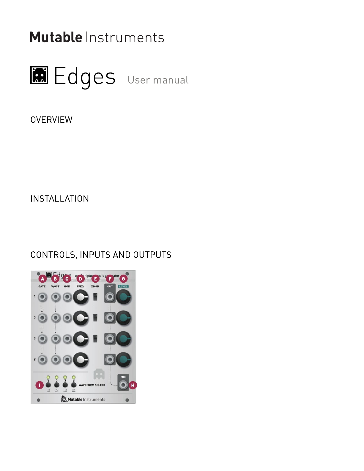
A1 .. A4. GATE: Channel gate input. When the sequencer is off, this input acts as a binary VCA - the
channel is off when the signal is 0V; on when the signal exceeds a 0.7V threshold. When the sequencer is
active, the channel is always on, and this input acts as a clock input, to step through the sequence. The
gate inputs are normalled. For example, if you connect a jack on channel 2’s gate, it will be used for
1 of 5
Page 2
Mutable Instruments | Edges
channels 3 and 4 unless a jack is connected in one of their gate inputs.
B1 .. B4. V/OCT: Channel frequency input. Just like the GATE inputs, these are also normalled across all
channels. This can be used, for example, to transpose a chord or polyphonic sequence from a single note
CV.
C1 .. C4. MOD: Channel frequency modulation input. This input serves the same purpose as the V/OCT
input (and is summed to it); but is not normalled from one channel to the other.
D1 .. D4. FREQ: Channel frequency control, spanning 6 octaves.
E1 .. E3. XMOD: This switch enables a special digital cross-modulation effect. From top to bottom:
Channel 1 to Channel 2 hard sync.1.
Channel 1 x Channel 2 ring modulation.2.
Channel 1 x Channel 3 ring modulation.3.
F1 .. F4. OUT: Channel individual output. When a jack is plugged in this output, the corresponding
channel is removed from the global mix.
G1 .. G4: Channel volume control, for the mixer. Not that this potentiometer does not affect the individual
outputs’ levels (they are always at full level).
H. MIX: Mixer output.
I. WAVEFORM SELECT: Press these switches to cycle through the various waveshapes available on
each channel. Hold a switch to modify the quantization/sequencing/calibration options of the
corresponding channel (see the “Channel options” section).
LED 1..4: They indicate the status of each channel’s gate input.
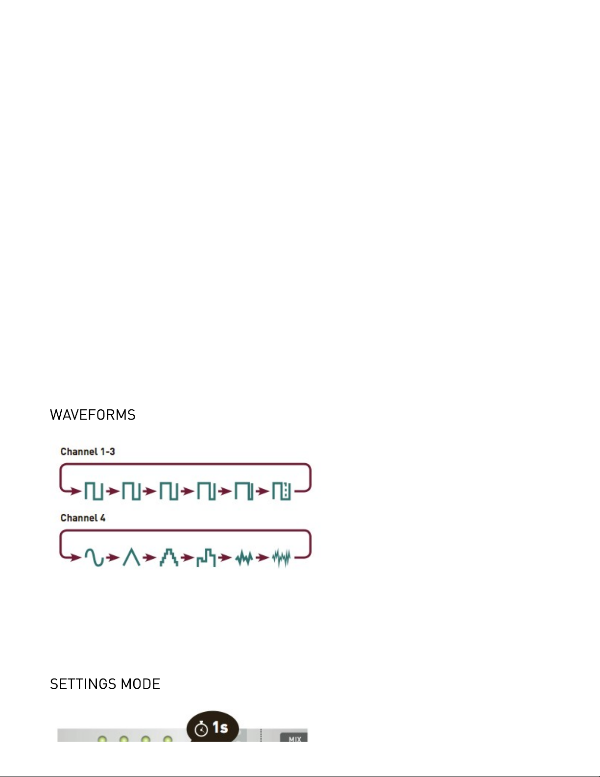
For channel 1, 2, and 3, the waveshapes are all square waves with 50%, 66%, 75%, 87%, 95% pulse or
CV controlled pulse width. With this last option, channel 4’s frequency input doubles as a PWM control.
For channel 4, the waveshapes are sine, triangle, NES triangle (with 16 loudness levels), sample-and-hold
noise, NES LSFR 1 (long cycle) and NES LSFR 2 (short cycle). LSFRs are linear feedback shift registers a digital technique for creating cyclic noise patterns.
2 of 5
Page 3

Mutable Instruments | Edges
Hold one of the 4 WAVEFORM SELECT switches to modify this channel’s options. Leds 3 and 4 will blink.
Press 1 to enable/disable semitone quantization on this channel. Led 1 indicates whether the quantizer is
enabled.
Press 2 to enable/disable the sequencer. Led 2 indicates whether the sequencer is enabled. Hold any one
of the 4 WAVEFORM SELECT switches to exit the settings mode.
Hold one of the 4 WAVEFORM SELECT switches to select the channel in which you want to record a
sequence. Leds 3 and 4 will blink.
Press 3 to start recording. Led 1 lights on to indicate the active step (step 1). Set the FREQ control on the
selected channel to the desired note; or enter a note from your CV keyboard or through your MIDI-CV
interface. Press the second switch to continue to the next step. Set the FREQ control on the selected
channel to the desired note for the second step. Press the third switch to continue, etc. To stop recording,
press the currently active step. For example, to record a 6 step sequence:
Press 3 to start recording. The sequencer starts at step 1.1.
Set CV2.
Press 23.
Set CV4.
Press 35.
Set CV6.
Press 47.
Set CV8.
3 of 5
Page 4

Mutable Instruments | Edges
Press 19.
Set CV
Press 2
Set CV
Press 2 again (to indicate that you don’t want to add a new step). You are done with recording. If you wanted
to continue the sequence, you would have pressed 3, set a CV, press 4, set a CV, and press 4 (the sequence
length is limited to 8 steps).
Edges’ is digitally calibrated. Please follow this procedure to calibrate all channels:
Unplug all jacks connected to the GATE, V/OCT and FM inputs.1.
Set all the FREQ potentiometers to their central position.2.
Connect the note CV output of a well-calibrated keyboard interface or MIDI->CV converter to the first
3.
channel’s V/OCT input. Because all V/OCT inputs are normalled, this signal will also be available for
calibrating the other channels.
Hold the channel 1 WAVEFORM SELECT switch until LEDs 3 and 4 blink. Press switch 4 (calibration).4.
The LEDs show this pattern: **oo, to indicate that you need to play a C2 note (CV equal to 1V). Once the note
5.
has been played, press switch 4 to continue.
The LEDs show this pattern: ****, to indicate that you need to play a C4 note (CV equal to 3V). Once the note
6.
has been played, press switch 4 continue. The channel is now calibrated.
Repeat the steps 4/ 5/ 6/ 7/ by holding the channels 2, 3 and 4 WAVEFORM SELECT switches.7.
This product is covered by Mutable Instruments’ warranty, for one year following the date of manufacture.
This warranty covers any defect in the manufacturing of this product. This warranty does not cover any
damage or malfunction caused by incorrect use - such as, but not limited to, power cables connected
backwards, excessive voltage levels, or exposure to extreme temperature or moisture levels.
The warranty covers replacement or repair, as decided by Mutable Instruments. Please contact our
customer service (support@mutable-instruments.net) for a return authorization before sending the
module. The cost of sending a module back for servicing is paid for by the customer.
Mutable Instruments encourages modding and hacking, but we will not service modified units or provide
any assistance in the realization of mods.
4 of 5
Page 5

Mutable Instruments | Edges
5 of 5
 Loading...