

Page 1
About Ears
Our take on Tom Whitwell’s
Mikrophonie
a perfect match for physical
synthesis modules like Rings or
Elements, but it can also be the
gateway between external audio
sources and your modular system.
module, Ears is
Installation
Ears requires a -12V / +12V power
supply (2x5 pin connector).
The ribbon cable connector must
be aligned so that the red stripe
of the ribbon cable (-12V) is on
the same side of the module’s
power header as the “Red stripe”
marking on the board. The module
draws 5mA from both the +12V
and the -12V supply rails.
The full manual can be found
online at
mutable-instruments.net/modules/ears/manual
For help and discussions, head to
mutable-instruments.net/forum
Ears
Contact microphone
Please refer to the online manual
for detailed information regarding
compliance with EMC directives
Page 2
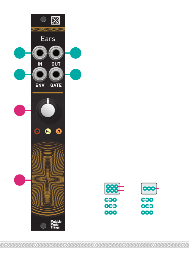
1 2
med.
Envelope
Follower
Gate
4V
Threshold
3 4
A
A. Gain control, 0 to 40dB
(loud! may cause clipping).
B. Contact microphone.
1. Hi-Z Audio input. Amplifies
an external source. Patching
a cable here disconnects the
contact microphone.
2. Audio output. The red LED
indicates clipping.
3. Envelope CV output. The
white LED indicates the envelope CV level.
4. Gate output. Emits +8V
when the envelope exceeds a
threshold. Indicator: orange
LED.
The jumpers at the back of the
module adjust the response of
the envelope follower and gate
detector.
B
Detector
Attack
Release
fast
slow
The last setting is obtained by
removing the jumper.
1V
2V
 Loading...