

Page 1
Algorithms overview
Classic analog waveforms
Wave Description Timbre Color
CSAW
/\/|-_-_
/|/|-_-_
SYNC
FOLD
CS-80 imperfect
saw
Variable
waveshape
Classic sawtooth/square
2 square VCOs
with hardsync
Sine/triangle into
wavefolder
Digital synthesis
_|_|_|_
/|/| x3
-_ x3
RING
/|/|/|/|
/|/|_|_|
TOY*
2 detuned
harmonic combs
Triple saw and
triple square
3 ring-modulated sine waves
Swarm of 7
sawtooth waves
Comb filtered
sawtooth
Low-fi, circuitbent sounds
Notch width Notch
polarity
Waveshape Distortion/
filter
Pulse width Saw <->
square
VCO frequency ratio
Wavefolder
amount
Smoothness Detune
Osc. 2
detune
2/1 frequency ratio
Detune High-pass
Delay time Neg./pos.
Sample
reduction
VCO
balance
Sine <->
triangle
Osc. 3
detune
3/1 frequency ratio
filter
feedback
Bit toggling
ZLPF
ZPKF, ZBPF, ZHPF are variants of ZLPF with peaking,
band-pass, and high-pass filters
Direct synthesis
of low-pass filtered waveform
Cutoff
frequency
Waveshape
Vocal synthesis and formants
VOSM
VOWL
VFOF
FM
FBFM
WTFM
Sawtooth with
2-formants
Speaking-toy
vowel synthesis
Vowel synthesis a, e, i, o, u Gender
2-operator FM Modulation
2-operator FM
with feedback
Chaotic
2-operator FM
Formant 1
frequency
a, e, i, o, u Gender
index
Modulation
index
Modulation
index
Formant 2
frequency
Frequency
ratio
Frequency
ratio
Frequency
ratio
Physical simulations
BELL,
DRUM
PLUK
BOWD
Bell and
metallic drum
simulations
Plucked string Decay Plucking
Bowed string Friction Bowing
Decay Inharmo-
nicity
position
position
BLOW
FLUT
Reed and flute
simulations
Wavetables
WTBL
WMAP
WLIN
WTx4
21 wavetables Smooth
16x16 waves X position Y position
Linear wavetable
scanning
Quad wavetable
synthesis
Noise
NOIS
TWNQ
CLKN
CLOU
PRTC
QPSK
Tuned noise
(2-pole filter)
Noise sent to 2
resonators
Clocked digital
noise
Sinusoidal granular synthesis
Droplets granular synthesis
Modem noises Bit-rate Modulated
Air pressure Instrument
geometry
Quantized
wavetable
position
Wavetable
position
Wavetable
position
Filter
resonance
Resonance Resonators
Cycle length Quantization
Grain
density
Grain
density
wavetable
selection
Interpola-
tion quality
Chord type
Response,
LP to HP
frequency
ratio
Frequency
dispersion
Frequency
dispersion
data
Braids
Macro oscillator
Page 2
Installation
Front panel
Settings
Braids requires a -12V / +12V / +5V power supply (2x8
pin connector). The ribbon cable connector must be
aligned so that the red stripe of the ribbon cable (-12V)
is on the same side of the module’s power header as the
“Red stripe” marking on the board.
The power consumption is as follows:
-12V: 15mA; +12V: 15mA; +5V: 85mA.
Online manual and help
The full manual can be found online at
mutable-instruments.net/modules/braids/manual
For help and discussions, head to
mutable-instruments.net/forum/
Calibration
Calibrating Braids is as easy as playing a C2 and a C4
note from an accurate MIDI>CV interface or CV source.
Read more about this in the online manual!
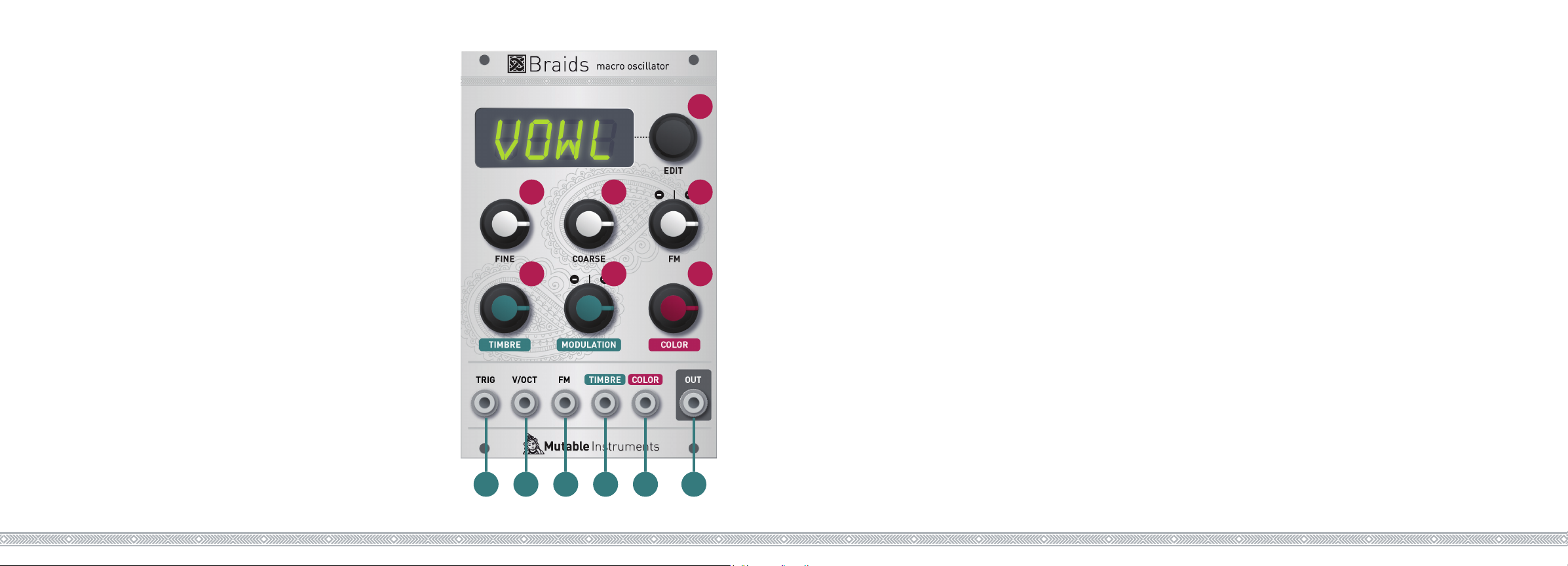
Controls
A
B
E
C
F
D
G
A. Display and encoder - when the module starts, they
show and modify the oscillator model.
B. C. Fine and coarse frequency controls.
D. FM attenuverter. Adjusts the amount and polarity of
frequency modulation from the FM input.
E. F. Timbre control, and timbre modulation attenu-
verter. Principal dimension of sound motion and wave-
shaping.
G. Color. Secondary dimension of waveshaping. The
function of Timbre and Color depends on the oscillator
type. Refer to the table on the other side!
Inputs and Outputs
1. Trigger input. Resets the oscillator phase. For the
physical modeling algorithms this input needs to be
triggered to “excite” the oscillator (or it won’t produce
any sound).
2. V/Oct. Main frequency control input, with V/Oct scale.
3. 4. 5. Frequency, timbre, and color modulation CV
inputs.
1
2 3
4
5
6
6. Audio output.
Click the encoder to display a list of settings. Scroll
through the settings and click to modify one of them.
Once the value has been modified, click to confirm and
get back to the menu. Selecting the first option (WAVE)
saves all the current settings in memory and brings
you back to the module’s initial state (oscillator model
selection).
An overview of the available settings:
BITS / RATE is the bit-depth and sample rate of the
audio output, for digital grit and crunchiness!
QNTZ applies a semitone or quartertone quantization to
the V/Oct input.
FLAT/DRFT/SIGN create various VCO-like instabilities.
TRIG allows a simple AD envelope (6 preset shapes) to
shape the sound whenever a trigger is received on the
TRIG input.
 Loading...