

Musway P2 operation manual

VERSION 1.0
P2
2-CHANNEL CLASS D AMPLIFIER

ENGLISH
SAFETY INSTRUCTIONS
THE PURCHASED DEVICE IS ONLY SUITABLE FOR AN OPERATION WITH A 12V ON-BOARD ELECTRICAL SYSTEM OF A VEHICLE. Otherwise re hazard, risk of injury and electric shock consists.
PLEASE DO NOT MAKE ANY OPERATION OF THE SOUND SYSTEM, WHICH DISTRACT YOU FROM A
SAFE DRIVING. Do not make any procedures, which demand a longer attention. Perform these operations not
until you have stopped the vehicle on a safe place. Otherwise the risk of accident consists.
ADJUST THE SOUND VOLUME TO AN APPROPRIATE LEVEL, THAT YOU ARE STILL ABLE TO HEAR
EXTERIOR NOISES WHILE DRIVING. High performance sound systems in vehicles may generate the acous-
tic pressure of a live concert. The permanent listening to extreme loud music may cause the loss of your hearing abilities. The hearing of extreme loud music while driving may derogate your cognition of warning signals in
the trafc. In the interests of the common safeness, we suggest to drive with a lower sound volume. Otherwise
the risk of accident consists.
DO NOT COVER COOLING VENTS AND HEAT SINKS. Otherwise this may cause heat accumulation in the
device and re hazard consists.
DO NOT OPEN THE DEVICE. Otherwise re hazard, risk of injury and electric shock consists. Also this may
cause a loss of the warranty.
REPLACE FUSES ONLY WITH FUSE WITH THE SAME RATING. Otherwise re hazard and risk of electric
shock consists.
DO NOT USE THE DEVICE ANY LONGER, IF A MALFUNCTION OCCURS, WHICH REMAINS NOT REMEDIED. Refer in this case to the chapter TROUBLE SHOOTING. Otherwise risk of injury and the damage of
the device consists. Commit the device to an authorized retailer.
INTERCONNECTION AND INSTALLATION SHOULD BE ACCOMPLISHED BY SKILLED STAFF ONLY. The
interconnection and installation of this device demands technical aptitude and experience. For your own safeness, commit the interconnection and installation to your car audio retailer, where you have purchased the
device.
DISCONNECT THE GROUND CONNECTION FROM THE VEHICLE’S BATTERY BEFORE INSTALLATION.
Before you start with the installation of the sound system, disconnect by any means the ground supply wire
from the battery, to avoid any risk of electric shock and short circuits.
CHOOSE AN APPROPRIATE LOCATION FOR THE INSTALLATION OF THE DEVICE. Look for an appropriate location for the device, which ensures a sufcient air circulation. The best places are spare wheel cavities,
and open spaces in the trunk area. Less suitable are storage spaces behind the side coverings or under the
car seats.
DO NOT INSTALL THE DEVICE AT LOCATIONS, WHERE IT WILL BE EXPOSED TO HIGH HUMIDITY AND
DUST. Install the device at a location, where it will be protected from high humidity and dust. If humidity and
dust attain inside the device, malfunctions may be caused.
MOUNT THE DEVICE AND OTHER COMPONENTS OF THE SOUND SYSTEM SUFFICIENTLY. Otherwise
the device and components may get loose and act as dangerous objects, which could cause serious harm and
damages in the passenger room.
ENSURE CORRECT CONNECTION OF ALL TERMINALS. Faulty connections may could cause re hazard
and lead to damages of the device.
2

ENGLISH
SAFETY INSTRUCTIONS
MOUNT THE DEVICE AND OTHER COMPONENTS OF THE SOUND SYSTEM SUFFICIENTLY. Otherwise
the device and components may get loose and act as dangerous objects, which could cause serious harm and
damages in the passenger room.
ENSURE NOT TO DAMAGE COMPONENTS, WIRES AND CABLES OF THE VEHICLE WHEN YOU DRILL
THE MOUNTING HOLES. If you drill the mounting holes for the installation into the vehicle’s chassis, ensure
by any means, not to damage, block or tangent the fuel pipe, the gas tank, other wires or electrical cables.
DO NOT INSTALL AUDIO CABLES AND POWER SUPPLY WIRES TOGETHER. Ensure while installation
not to lead the audio cables between the head unit and the processor together with the power supply wires
on the same side of the vehicle. The best is a areal separated installation in the left and right cable channel of
the vehicle. Therewith a overlap of interferences on the audio signal will be avoided. This stands also for the
equipped bass-remote wire, which should be installed not together with the power supply wires, but rather with
the audio signal cables.
ENSURE THAT CABLES MAY NOT CAUGHT UP IN CLOSE-BY OBJECTS. Install all the wires and cables
like described on the following pages, therewith these may not hinder the driver. Cables and wires which are
installed close-by the steering wheel, gear lever or the brake pedal, may caught up and cause highly dangerous situations.
DO NOT SPLICE ELECTRICAL WIRES. The electrical wires should not be bared, to provide power supply to
other devices. Otherwise the load capacity of the wire may get overloaded. Use therefor a appropriate distribution block. Otherwise re hazard and risk of electric shock consists.
DO NOT USE BOLTS AND SCREW NUTS OF THE BRAKE SYSTEM AS GROUND POINT. Never use for
the installation or the ground point bolts and screw-nuts of the brake system, steering system or other securityrelevant components. Otherwise re hazard consists or the driving safety will be derogated.
ENSURE NOT TO BEND OR SQUEEZE CABLES AND WIRES BY SHARP OBJECTS. Do not install cables
and wires not close-by movable objects like the seat rail or may be bent or harmed by sharp and barbed edges.
If you lead a wire or cable through the hole in a metal sheet, protect the insulation with a rubber grommet.
KEEP AWAY SMALL PARTS AND JACKS FROM CHILDREN. If objects like these will be swallowed, the risk
of serious injuries consists. Consult promptly a medical doctor, if a child swallowed a small object.
3

ENGLISH
TECHNICAL SPECIFICATIONS
Output Power RMS
Output Power Max.
Loudspeaker impedance (stereo)
Frequency Response
Total Harmonic Distortion
Signal-to-Noise Ratio
Input Sensitivity
Input Impedance
Operating Voltage
Fuse Rating
Dimensions (L x H x W)
All Specications are subject to change
SCOPE OF DELIVERY
1 x P2 Amplier
4 x Mounting Bracket incl. screws
1 x Detachable Plug for power connection
1 x Detachable Plug for the speaker output
1 x Owner’s Manual (English/German)
2 x 70 W @ 4 Ohms
2 x 10⁵ W @ 2 Ohms
1 x 210 W @ 4 Ohms bridged
2 x 140 W @ 4 Ohms
2 x 210 W @ 2 Ohms
1 x 420 W @ 4 Ohms bridged
2 – 8 Ohms
5 – 60 000 Hz (-3 dB)
< 0,05 % (1 kHz)
> 97 dB
0,6 – 16 V
100 kOhms
+12 V (7 – 16 V), negative ground
1 x 20 A
124 x 36 x 75 mm
4
ENGLISH
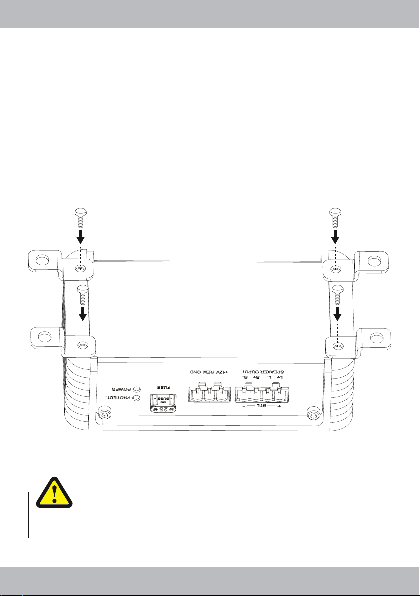
MECHANICAL INSTALLATION
• Avoid any damages on the components of the vehicle like air bags, cables, board computer, seat belts, gas
tank or the like.
• Ensure that the chosen location provides a sufcient air circulation for the amplier. Do not mount the device
into small or sealed spaces without air circulation near by heat dispersing parts or electrical parts of the
vehicle.
• Do not mount the amplier on top of a subwoofer box or any other vibrating parts, whereby parts could
loosen inside.
• The wires and cables of power supply and the audio signal must be as short as possible to avoid any losses
and interferences.
WARNING
Before you start with the installation, disconnect necessarily the GROUND connection wire
from the battery to avoid any risk of electric shocks and short circuits.
5
ENGLISH
ELECTRICAL INTERCONNECTION
BEFORE CONNECTING
For the professional installation of a sound system, car audio retail stores offers appropriate wiring kits. Ensure
a sufcient prole section (at least Ø 5 mm), a suitable fuse rating and the conductivity of the cables when you
purchase your wiring kit. Clean and remove rust-streaked and oxidized areas on the contact points of the battery and the ground connection. Make sure that all screws are xed tight after the installation, because loose
connections cause malfunctions, insufcient power supply or interferences.
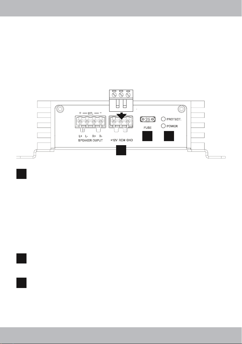
2 3
1
+12V REM GND
1
Connect the terminal +12V with the +12V pole of the vehicle’s battery. Use a suitable cable with a
sufcient cross section (at least Ø 5 mm) and install an additional in-line fuse. For safety reasons the
distance between the fuse block and the battery should be shorter than 30 cm. Do not set in the fuse
into the fuse block until the installation is accomplished.
Connect the remote turn-on-wire from the head unit or the additional amplier with the REM terminal
of the P2 amplier. A cable with a cross-section of 0.5 mm
Connect the terminal GND (ground) with a suitable contact ground point on the vehicle’s chassis.
The ground wire must be as short as possible and must be connected to a blank metallic point at
the vehicle’s chassis. Ensure that this ground point has a stable and safe electric connection to the
negative “–”pole of the battery. Check this ground wire from the battery to the ground point if possible
and enforce it, if required. Use a ground wire with a sufcient cross section (at least Ø 5 mm) and the
same size like the positive + power supply wire. This helps reduce most of the interference than can
occur in audio reproduction.
2
is adequate.
FUSE
2
The inserted fuse (25 A blade) protects the amplier from shorts and capacity overload. If you need to
replace the fuse, make sure to use the same type of fuse with the same rating.
PROTECTION/POWER LED
3
The POWER LED lights up green, if the amplier is in operation.
The PROTECTION LED lights up red, when the amplier is overheated, or a short circuit occurs
respective a too low impedance load is connected to the speaker outputs. If this events, the internal
built-in protection circuit shuts down the amplier automatically. The amplier should work again properly after you have solved the problems. Please refer to the section TROUBLE SHOOTING”.
6
 Loading...