

Page 1

MG
COMPONENT SPEAKERS
Page 2

EINBAUHINWEISE
Der erste Schritt bei der Installation der Lautsprecher sollte die sorgfältige
Planung sein. Folgen Sie einfach diesen Vorschlägen um das bestmögliche
Resultat zu erreichen.
1. Wählen Sie eine Position für die einzelnen Komponenten, bei der das
Signal am besten ohne Hindernisse im Fahrgastraum verteilt wird. Beachten Sie dabei auch die Position der Sitze, Nackenstützen und anderer
Aufbauten im Innenraum.
2. Montieren Sie die Lautsprecher rechts und links in der selben Anordnung,
d.h. sie sollten auf der gleichen Höhe und direkt gegenüber zueinander
eingebaut werden. Vermeiden Sie wenn möglich, dass ein Lautsprecher
höher, tiefer, weiter weg oder näher wie der gegenüberliegende Lautsprecher montiert wird.
3. Achten Sie beim Einbau darauf, dass der Abstand zwischen dem Hochtöner und dem Mitteltöner möglichst gering ist.
4. Überprüfen Sie vor dem Bohren von Montagelöchern immer, was sich
hinter der gewählten Montageäche bendet. Bitte beschädigen Sie auf
keinen Fall Fensterhebevorrichtungen, Kabelbäume, den Tank oder andere Fahrzeugteile.
5. Sie erreichen das beste Klangresultat, wenn die Lautsprecher fachgerecht in einem Türpanel oder einer Heckablage fest montiert werden.
Lücken oder lose Stellen zwischen Lautsprecherkorb und Montageober-
äche sollten abgedämmt bzw. geschlossen werden.
6. Bitte behandeln Sie die Komponenten mit Sorgfalt während des Einbaus,
andernfalls könnten diese ernsthaft beschädigt werden.
7. Bitte achten Sie beim Anschließen der einzelnen Komponenten stets auf
die korrekte Polarität (+ / –) der Anschlüsse.
8. Schließen Sie die Lautsprecher niemals an den Masseanschluss oder an
die Karosserie des Fahrzeugs an.
Page 3

TECHNISCHE DATEN
MG6.2W
16,5 cm (6.5“) Tiefmitteltöner
Belastbarkeit RMS 125 Watt
Belastbarkeit max. 250 Watt
Impedanz 4 Ohm
Frequenzgang 39 - 5000 Hz
Aluminium-Papier-Verbund-Membran
Einbautiefe 67 mm
Einbauöffnung Ø 143 mm
Außendurchmesser Ø 166 mm
MG6.2T
26 mm (1.1“) Hochtöner
Belastbarkeit RMS 125 Watt
Belastbarkeit max. 250 Watt
Impedanz 4 Ohm
Frequenzgang 2200 - 30000 Hz
Gewebe-Membran
Einbautiefe 19,5 mm
Einbauöffnung Ø 44 mm
Außendurchmesser Ø 49 mm
MG3M
7,5 cm (3“) Mitteltöner
Belastbarkeit RMS 60 Watt
Belastbarkeit max. 120 Watt
Impedanz 4 Ohm
Frequenzgang 200 - 18000 Hz
Aluminium-Membran
Einbautiefe 40 mm
Einbauöffnung Ø 73 mm
Außendurchmesser Ø 90 mm
MG2X
2-Wege Frequenzweiche
Belastbarkeit RMS 125 Watt
Belastbarkeit max. 250 Watt
Trennfrequenz 2800 Hz
5-fach Hochtonpegelanpassung
Breite 85 mm
Höhe 40 mm
Länge 145 mm
Page 4
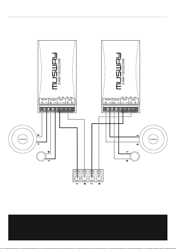
ANSCHLUSSDIAGRAMM MG6.2C
LINKS RECHTS
MG2X MG2X
MG6.2W
MG6.2T
L R
LAUTSPRECHER-
AUSGÄNGE
VERSTÄRKER
WICHTIG:
Bitte achten Sie unbedingt auf die korrekte Polarität (+ oder –)
aller Anschlüsse und Verbindungen.
MG6.2W
MG6.2T
Page 5
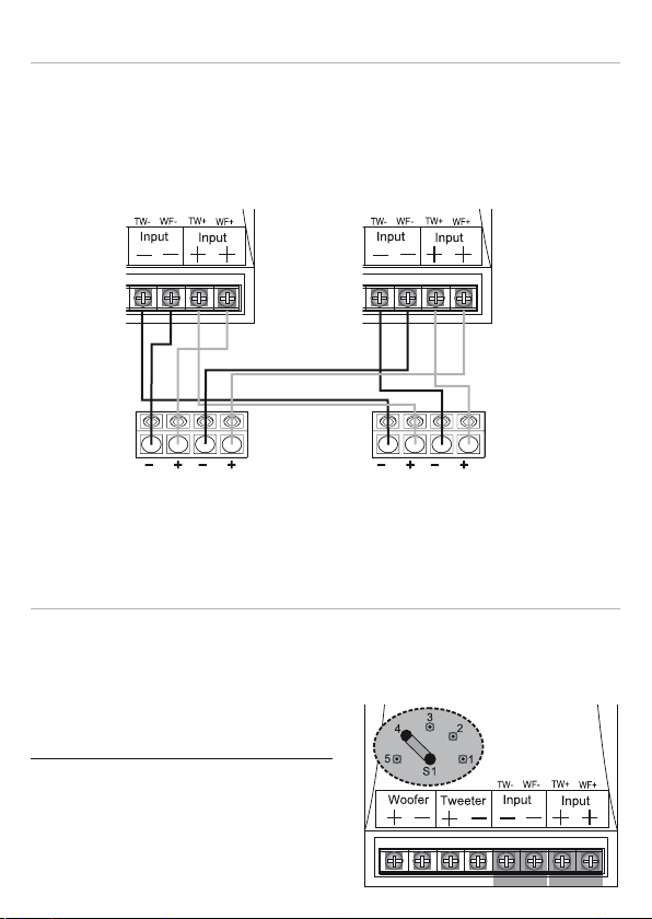
Bi-AMPING MG2X
Durch Entfernen der Kontaktbrücken an INPUT – und INPUT +, kann die
Frequenzweiche auch im Bi-Amping Betrieb betrieben werden. Damit können Sie den Tiefmitteltöner und den Hochtöner jeweils getrennt mit einem
Verstärker bzw. Kanalpaar betrieben.
LINKS RECHTS
L LR R
VERSTÄRKER 1
ODER KANALPAAR 1/2
FÜR TIEFMITTELTÖNER
VERSTÄRKER 2
ODER KANALPAAR 3/4
FÜR HOCHTÖNER
HOCHTONPEGELANPASSUNG MG2X
Zum Anpassen des Hochtonpegels müssen Sie den Gehäusedeckel der Frequenzweiche entfernen und an der Steckbrücke unten links, die gewünschte
Kombination wählen. Ziehen Sie die Steckbrücke vorsichtig ab und stecken
Sie sie an der gewünschten Position ein.
Folgende Kombinationen sind möglich:
S1 – Position 1 = 0 dB
S1 – Position 2 = - 2 dB
S1 – Position 3 = - 4 dB
S1 – Position 4 = - 6 dB
S1 – Position 5 = - 8 dB
Page 6
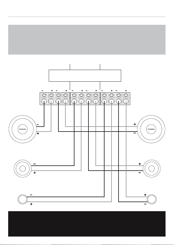
ANSCHLUSSDIAGRAMM MG6.3A
Im aktiven Betrieb ohne Frequenzweiche müssen Sie
ACHTUNG:
unbedingt die angegebenen Frequenzbereiche beachten.
Zu tiefe Frequenzen beschädigen die Lautsprecher.
LAUTSPRECHERAUSGÄNGE VERSTÄRKER
Empfohlene Übergangsfrequenzen:
CH1 CH2 CH3 CH4 CH5 CH6
4400 Hz @ 12dB400 Hz @ 12dB
LINKS RECHTS
MG6.2W
MG3M MG3M
MG6.2T MG6.2T
MG6.2W
Bitte achten Sie unbedingt auf die korrekte Polarität (+ oder –)
WICHTIG:
aller Anschlüsse und Verbindungen.
Page 7
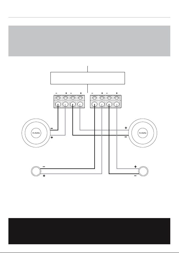
ANSCHLUSSDIAGRAMM MG6.2A
Im aktiven Betrieb ohne Frequenzweiche müssen Sie
ACHTUNG:
unbedingt die angegebenen Frequenzbereiche beachten.
Zu tiefe Frequenzen beschädigen die Lautsprecher.
LAUTSPRECHERAUSGÄNGE VERSTÄRKER
Empfohlene Übergangsfrequenz:
3300 Hz @ 12dB
CH1 CH2 CH3 CH4
LINKS RECHTS
MG6.2W MG6.2W
MG6.2T MG6.2T
Bitte achten Sie unbedingt auf die korrekte Polarität (+ oder –)
WICHTIG:
aller Anschlüsse und Verbindungen.
Page 8

INSTALLATION NOTES
The rst step of installing a speaker system is thorough planning. Choose a
suitable location for your speaker components carefully. Follow these sug-
gestions to ensure proper imaging and maximum performance:
1. Choose a location that offers the least amount of obstruction between
the components and your ears. Pay also attention to the position of the
seats, headrests and other constructional systems in the interior space
of the car.
2. Try to mount the speakers on the same arrangement. They should be
installed at the same height and directly across from each other. Do not
mount one speaker higher, lower, further forward or further backward from
the opposite speaker.
3. The tweeter should always be installed as close as possible to the speak-
ers.
4. Always take a look behind the chosen mounting locations to ensure that
there is proper clearance for the rear of the speakers and avoid obstructions such as window tracks, wire harnesses, gas tank etc.
5. Maximum performance is achieved when the speaker is securely mounted to a door panel or rear speaker deck. There should be no gaps between the speaker basket and the mounting surface
6. Please handle the components with care, otherwise they will get damaged.
7. Please pay attention to the correct polarity (+ or -) for all terminals and
connections.
8. Never connect the speakers to the electrical ground or with the body of
the vehicle.
Page 9

SPECIFICATIONS
MG6.2W
16,5 cm (6.5“) Midbass Woofer
Power Rating RMS 125 Watts
Power Rating max. 250 Watts
Impedance 4 Ohms
Frequency Range 39 - 5000 Hz
Aluminum-paper Composite Cone
Mounting Depth 67 mm
Mounting Diameter Ø 143 mm
Outer Diameter Ø 166 mm
MG6.2T
26 mm (1.1“) Tweeter
Power Rating RMS 125 Watts
Power Rating max. 250 Watts
Impedance 4 Ohms
Frequency Range 2200 - 30000 Hz
Silk Diaphragm Dome
Mounting Depth 19,5 mm
Mounting Diameter Ø 44 mm
Outer Diameter Ø 49 mm
MG3M
7,5 cm (3“) Midrange Speaker
Power Rating RMS 60 Watts
Power Rating max. 120 Watts
Impedance 4 Ohms
Frequency Range 200 - 18000 Hz
Aluminum Cone
Mounting Depth 40 mm
Mounting Diameter Ø 73 mm
Outer Diameter Ø 90 mm
MG2X
2-Way Crossover
Power Rating RMS 125 Watts
Power Rating max. 250 Watts
Crossover Frequency 2800 Hz
5-fold Tweeter Level Adjustment
Width 85 mm
Height 40 mm
Length 145 mm
Page 10
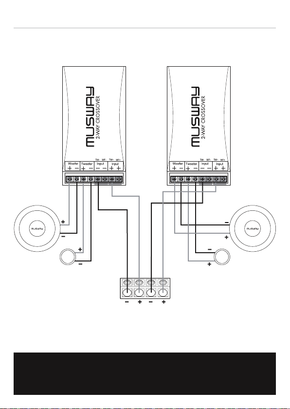
CONNECTION DIAGRAM MG6.2C
LEFT RIGHT
MG2X MG2X
MG6.2W
MG6.2T
L R
SPEAKER
OUTPUTS
AMPLIFIER
IMPORTANT:
Please pay attention to the correct polarity (+ or -)
for all terminals and connections.
MG6.2W
MG6.2T
Page 11
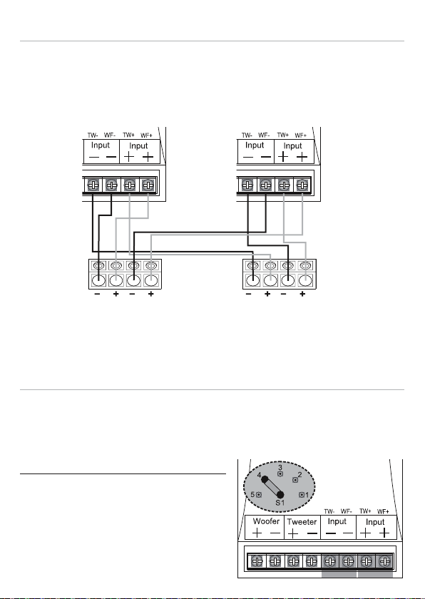
Bi-AMPING MG2X
By removing the contact bridges at INPUT - and INPUT +, the crossover can
also be operated in bi-amping mode. This allows you to operate the midbass
speaker and the tweeter separately with an amplier or channel pair.
LEFT RIGHT
L LR R
AMPLIFIER 1
OR CHANNELPAIR 1/2
FOR MIDBASS SPEAKER
AMPLIFIER 2
OR CHANNELPAIR 3/4
FOR MIDBASS SPEAKER
TWEETER LEVEL ADJUSTMENT MG2X
To adjust the tweeter level, you have to remove the cover of the crossover
and select the desired combination on the jumper at the bottom left. Carefully
pull out the jumper and insert it in the desired position.
The following combinations are possible:
S1 – Position 1 = 0 dB
S1 – Position 2 = - 2 dB
S1 – Position 3 = - 4 dB
S1 – Position 4 = - 6 dB
S1 – Position 5 = - 8 dB
Page 12
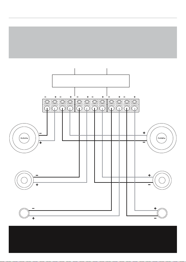
CONNECTION DIAGRAM MG6.3A
In active operation without a crossover, it is essential
ATTENTION:
to observe the specied frequency ranges.
Too low frequencies damage the speakers.
SPEAKER OUTPUTS AMPLIFIER
Recommended Crossover Frequencies:
CH1 CH2 CH3 CH4 CH5 CH6
4400 Hz @ 12dB400 Hz @ 12dB
LEFT RIGHT
MG6.2W
MG3M MG3M
MG6.2T MG6.2T
MG6.2W
Please pay attention to the correct polarity (+ or -)
IMPORTANT:
for all terminals and connections.
Page 13
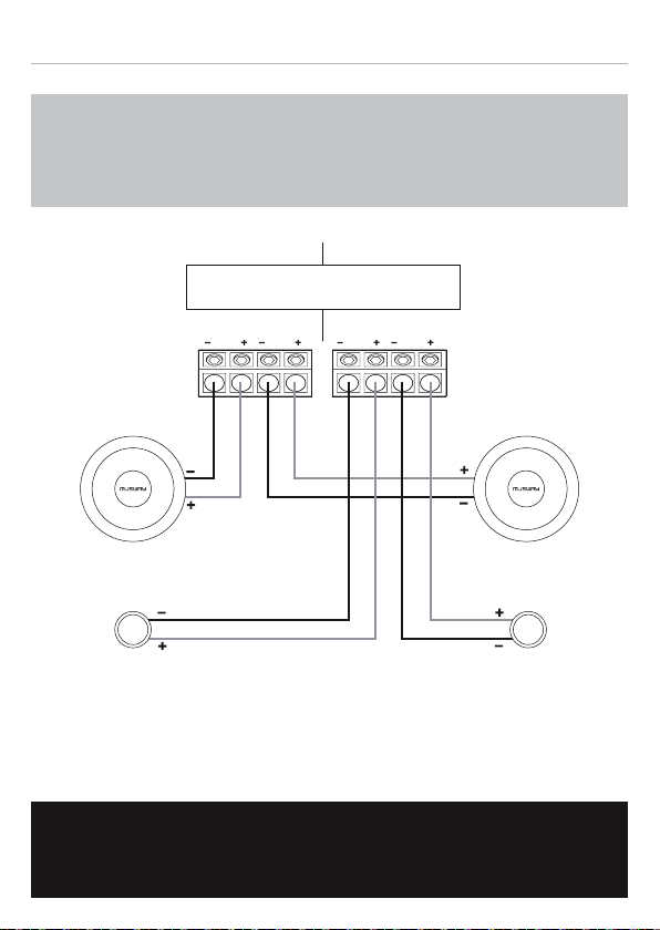
CONNECTION DIAGRAM MG6.2A
In active operation without a crossover, it is essential
ATTENTION:
to observe the specied frequency ranges.
Too low frequencies damage the speakers.
SPEAKER OUTPUTS AMPLIFIER
Recommended Crossover Frequency:
3300 Hz @ 12dB
CH1 CH2 CH3 CH4
LEFT RIGHT
MG6.2W MG6.2W
MG6.2T MG6.2T
Please pay attention to the correct polarity (+ or -)
IMPORTANT:
for all terminals and connections.
Page 14

NOTES
Page 15

NOTES
Page 16

MUSWAY is a brand of Audio Design GmbH
Am Breilingsweg 3 · D-76709 Kronau
Tel. +49 7253 - 9465-0 · Fax +49 7253 - 946510
© Audio Design GmbH, All Rights Reserved
www.musway.de
 Loading...