

Page 1

VERSION 1.1
M12
12-CHANNEL CLASS D AMPLIFIER
WITH 16-CHANNEL DSP
Page 2

ENGLISH
TECHNICAL SPECIFICATIONS
POWER SUPPLY
Voltage: 8 - 15 VDC
Idle current: 3.2 A
Switched off: <0.1 mA
Remote IN: 7,5 - 15 VDC (1 mA)
Remote OUT: 11 - 15 VDC (200 mA)
Fuse: 40 A x 2
AMPLIFIER STAGE
Distortion - THD (1 kHz @ 4 Ω, 90% Power): 0.05 %
Bandwidth (-3 dB, 2 V RMS, 4Ω): 15 Hz - 22 kHz
S/N ratio @ A weighted, 1 V, Max. Power: 95 dB A
Damping factor @ 1 kHz, 2 V RMS, 4 Ω: > 70
Input sensitivity: 8 - 24 V RMS (High-level); 2 - 6 V RMS (Low-level); 1 - 8 V RMS (AUX)
Input impedance: 13 Ω (High-level); 47 kΩ (Low-level)
LOAD IMPEDANCE (MIN):
@ 12CH: 2 Ω
@ Bridged: 4 Ω
OUTPUT POWER (RMS) @ 14.4 VDC, 1% THD*:
@ 4 Ω: 85 W
@ 2 Ω: 120 W
Bridged @ 4 Ω: 240 W
SIGNAL OUTPUTS
RCA OUT CH13/14 & CH15/16: 5 V RMS Max.
* In typical multi-channel applications (2- / 3-way systems + rear speakers + subwoofer)
Declaration of Conformity
Audio Design GmbH hereby declares that the MUSWAY M12 device complies with
Directive 2014/53/EU. The full declaration of conformity can be viewed at www.musway.de/CE
2
Page 3

ENGLISH
TECHNICAL SPECIFICATIONS
DIGITAL SIGNAL PROCESSOR (64 bit Clock speed: 295 MHz)
Crossover: Full / Hi Pass / Lo Pass / Band Pass
Crossover type and slope: Bessel / Butterworth / Linkwitz @ 6/12/18/24/30/36/42/48 dB
Crossover Frequency: 1 Hz step @ 20 Hz - 20 kHz
Phase inversion: 0° / 180°
Output Equalizer: 31-Band Parametrical Equalizer: ±12 dB
Time Alignment Distance: 0 - 692 cm
Time Alignment Delay: 0 - 17 ms
Time Alignment Step: 0,08 ms; 2,8 cm
Time Alignment Fine Set: 0,02 ms; 0,7 cm
Presets (Local Stored): 6 Presets
GENERAL REQUIREMENTS
PC connections Micro USB (1.1 / 2.0 / 3.0)
Software/PC requirements: Microsoft Windows (32/64 bit):
XP, Vista, Windows 7, Windows 8, Windows 10
Graphic card min. resolution: 1024 x 768
Ambient operating temperature range: 0 - 55 °C
SIZE / WEIGHT
Size without brackets (mm): 340 x 48 x 171,5
Net Weight (kg): 3,2
SCOPE OF DELIVERY
1 x M12 DSP Amplier
1 x 1,5 m USB Cable
1 x 24-pole Cable Adapter (High Level Inputs)
1 x 24-pole Cable Adapter (Speaker Outputs)
1 x 4-pole Cable Adapter (REM IN/OUT)
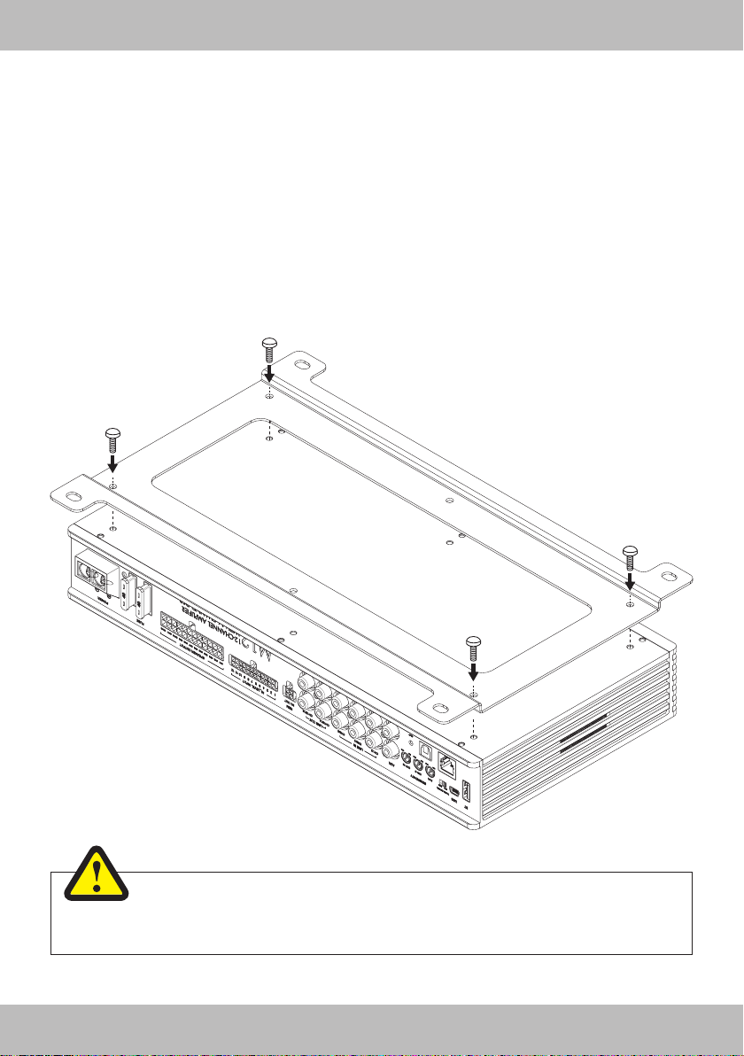
1 x Mounting Plate incl. Screws
1 x Owner’s Manual (English/German)
2 x 40 A replacement fuse
1 x 3 mm hex key
3
Page 4

ENGLISH
SAFETY INSTRUCTIONS
THE PURCHASED DEVICE IS ONLY SUITABLE FOR AN OPERATION WITH A 12V ON-BOARD ELECTRICAL SYSTEM OF A VEHICLE. Otherwise re hazard, risk of injury and electric shock consists.
PLEASE DO NOT MAKE ANY OPERATION OF THE SOUND SYSTEM, WHICH DISTRACT YOU FROM A
SAFE DRIVING. Do not make any procedures, which demand a longer attention. Perform these operations not
until you have stopped the vehicle on a safe place. Otherwise the risk of accident consists.
ADJUST THE SOUND VOLUME TO AN APPROPRIATE LEVEL, THAT YOU ARE STILL ABLE TO HEAR
EXTERIOR NOISES WHILE DRIVING. High performance sound systems in vehicles may generate the acous-
tic pressure of a live concert. The permanent listening to extreme loud music may cause the loss of your hear-
ing abilities. The hearing of extreme loud music while driving may derogate your cognition of warning signals in
the trafc. In the interests of the common safeness, we suggest to drive with a lower sound volume. Otherwise
the risk of accident consists.
DO NOT COVER COOLING VENTS AND HEAT SINKS. Otherwise this may cause heat accumulation in the
device and re hazard consists.
DO NOT OPEN THE DEVICE. Otherwise re hazard, risk of injury and electric shock consists. Also this may
cause a loss of the warranty.
REPLACE FUSES ONLY WITH FUSE WITH THE SAME RATING. Otherwise re hazard and risk of electric
shock consists.
DO NOT USE THE DEVICE ANY LONGER, IF A MALFUNCTION OCCURS, WHICH REMAINS NOT REMEDIED. Refer in this case to the chapter TROUBLE SHOOTING. Otherwise risk of injury and the damage of
the device consists. Commit the device to an authorized retailer.
INTERCONNECTION AND INSTALLATION SHOULD BE ACCOMPLISHED BY SKILLED STAFF ONLY. The
interconnection and installation of this device demands technical aptitude and experience. For your own safeness, commit the interconnection and installation to your car audio retailer, where you have purchased the
device.
DISCONNECT THE GROUND CONNECTION FROM THE VEHICLE’S BATTERY BEFORE INSTALLATION.
Before you start with the installation of the sound system, disconnect by any means the ground supply wire
from the battery, to avoid any risk of electric shock and short circuits.
CHOOSE AN APPROPRIATE LOCATION FOR THE INSTALLATION OF THE DEVICE. Look for an appropri-
ate location for the device, which ensures a sufcient air circulation. The best places are spare wheel cavities,
and open spaces in the trunk area. Less suitable are storage spaces behind the side coverings or under the
car seats.
DO NOT INSTALL THE DEVICE AT LOCATIONS, WHERE IT WILL BE EXPOSED TO HIGH HUMIDITY AND
DUST. Install the device at a location, where it will be protected from high humidity and dust. If humidity and
dust attain inside the device, malfunctions may be caused.
MOUNT THE DEVICE AND OTHER COMPONENTS OF THE SOUND SYSTEM SUFFICIENTLY. Otherwise
the device and components may get loose and act as dangerous objects, which could cause serious harm and
damages in the passenger room.
ENSURE CORRECT CONNECTION OF ALL TERMINALS. Faulty connections may could cause re hazard
and lead to damages of the device.
4
Page 5

ENGLISH
SAFETY INSTRUCTIONS
MOUNT THE DEVICE AND OTHER COMPONENTS OF THE SOUND SYSTEM SUFFICIENTLY. Otherwise
the device and components may get loose and act as dangerous objects, which could cause serious harm and
damages in the passenger room.
ENSURE NOT TO DAMAGE COMPONENTS, WIRES AND CABLES OF THE VEHICLE WHEN YOU DRILL
THE MOUNTING HOLES. If you drill the mounting holes for the installation into the vehicle’s chassis, ensure
by any means, not to damage, block or tangent the fuel pipe, the gas tank, other wires or electrical cables.
DO NOT INSTALL AUDIO CABLES AND POWER SUPPLY WIRES TOGETHER. Ensure while installation
not to lead the audio cables between the head unit and the processor together with the power supply wires
on the same side of the vehicle. The best is a areal separated installation in the left and right cable channel of
the vehicle. Therewith a overlap of interferences on the audio signal will be avoided. This stands also for the
equipped bass-remote wire, which should be installed not together with the power supply wires, but rather with
the audio signal cables.
ENSURE THAT CABLES MAY NOT CAUGHT UP IN CLOSE-BY OBJECTS. Install all the wires and cables
like described on the following pages, therewith these may not hinder the driver. Cables and wires which are
installed close-by the steering wheel, gear lever or the brake pedal, may caught up and cause highly danger-
ous situations.
DO NOT SPLICE ELECTRICAL WIRES. The electrical wires should not be bared, to provide power supply to
other devices. Otherwise the load capacity of the wire may get overloaded. Use therefor a appropriate distribution block. Otherwise re hazard and risk of electric shock consists.
DO NOT USE BOLTS AND SCREW NUTS OF THE BRAKE SYSTEM AS GROUND POINT. Never use for
the installation or the ground point bolts and screw-nuts of the brake system, steering system or other securityrelevant components. Otherwise re hazard consists or the driving safety will be derogated.
ENSURE NOT TO BEND OR SQUEEZE CABLES AND WIRES BY SHARP OBJECTS. Do not install cables
and wires not close-by movable objects like the seat rail or may be bent or harmed by sharp and barbed edges.
If you lead a wire or cable through the hole in a metal sheet, protect the insulation with a rubber grommet.
KEEP AWAY SMALL PARTS AND JACKS FROM CHILDREN. If objects like these will be swallowed, the risk
of serious injuries consists. Consult promptly a medical doctor, if a child swallowed a small object.
10 ~ 90% 5 ~ 50°C
5
Page 6
ENGLISH
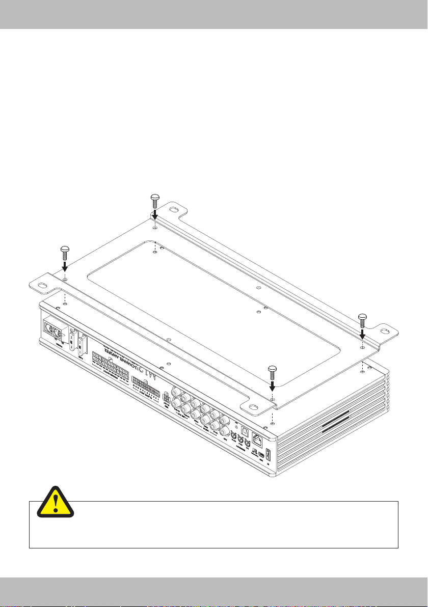
MECHANICAL INSTALLATION
• Avoid any damages on the components of the vehicle like air bags, cables, board computer, seat belts, gas
tank or the like.
• Ensure that the chosen location provides a sufcient air circulation for the amplier. Do not mount the device
into small or sealed spaces without air circulation near by heat dispersing parts or electrical parts of the
vehicle.
• Do not mount the amplier on top of a subwoofer box or any other vibrating parts, whereby parts could
loosen inside.
• The wires and cables of power supply and the audio signal must be as short as possible to avoid any losses
and interferences.
WARNING
Before you start with the installation, disconnect necessarily the GROUND connection wire
from the battery to avoid any risk of electric shocks and short circuits.
6
Page 7
INTERCONNECTION
BEFORE CONNECTING
For the professional installation of a sound system, car audio
retail stores offers appropriate wiring kits. Ensure a sufcient
prole section (refer to the table below) and a suitable fuse rating and the conductivity of the cables when you purchase your
wiring kit. Clean and remove rust-streaked and oxidized areas
on the contact points of the battery and the ground connection.
Make sure that all screws are xed tight after the installation,
because loose connections cause malfunctions, insufcient
power supply or interferences.
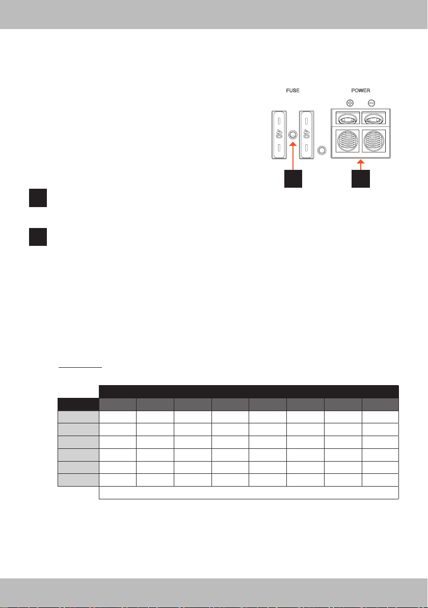
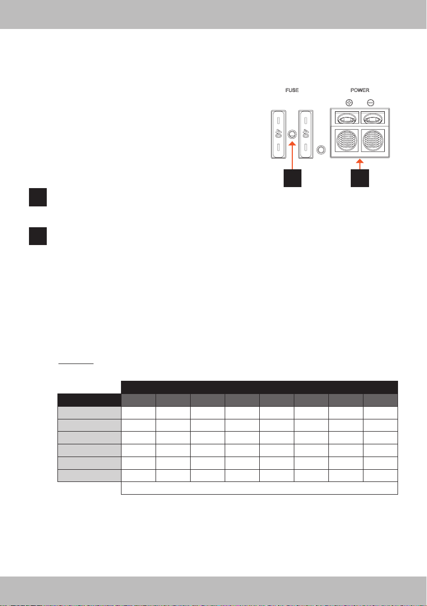
FUSE
1
The inserted fuses (2 x 40 A) are protecting the amplier from shorts and capacity overload. If you
need to replace the fuse, make sure to use the same type of fuse with the same rating.
POWER
2
Connect the POWER + terminal with the +12V pole of the vehicle’s battery. Use a suitable cable with
a sufcient cross section (refer to the table below).
Connect the POWER – terminal with a suitable contact ground point on the vehicle’s chassis. The
ground wire must be as short as possible and must be connected to a blank metallic point at the
vehicle’s chassis. Ensure that this ground point has a stable and safe electric connection to the negative “–”pole of the battery. Check this ground wire from the battery to the ground point if possible and
enforce it if required. Use a ground wire with a sufcient cross section (refer to the table below) and
the same size like the +12V power supply wire.
ADDITIONAL CABLE FUSE (NOT INCLUDED)
Install an extra fuse (not included) for the +12V power cable near the battery to secure the power
cable. The distance between the fuse and the battery should not exceed 30 cm. The fuse size must be
adapted to the cable cross-section of the installed power cable (see table below).
IMPORTANT: The fuse on the battery does not protect the amplier, but the cable between the battery
and the amplier against short circuits.
1
ENGLISH
2
Cable length in meters
Fuse Value 0 - 1,2 1,2 - 2,1 2,1 - 3,1 3,1 - 4,0 4,0 - 4,9 4,9 - 5,8 5,8 - 6,7 6,7 - 8,5
20 - 35 A 4 6 10 10 16 16 16 20
35 - 50 A 6 10 10 16 16 20 20 20
50 - 65 A 10 10 16 20 20 20 20 35
65 - 85 A 16 16 20 20 35 35 35 50
85 - 105 A 16 16 20 35 35 35 35 50
105 - 125 A 20 20 20 35 35 50 50 50
Minimum cable cross-section in mm
Recommended minimum cable cross-section to guarantee full amplier performance:
Up to a length of 3 m: 20 mm
From a length of 3 m: 25 mm2 / Full OFC cable
Replace defective fuses only with a new one of the same type and with the same fuse rating.
2
/ Full OFC cable
2
7
Page 8
ENGLISH
INTERCONNECTION
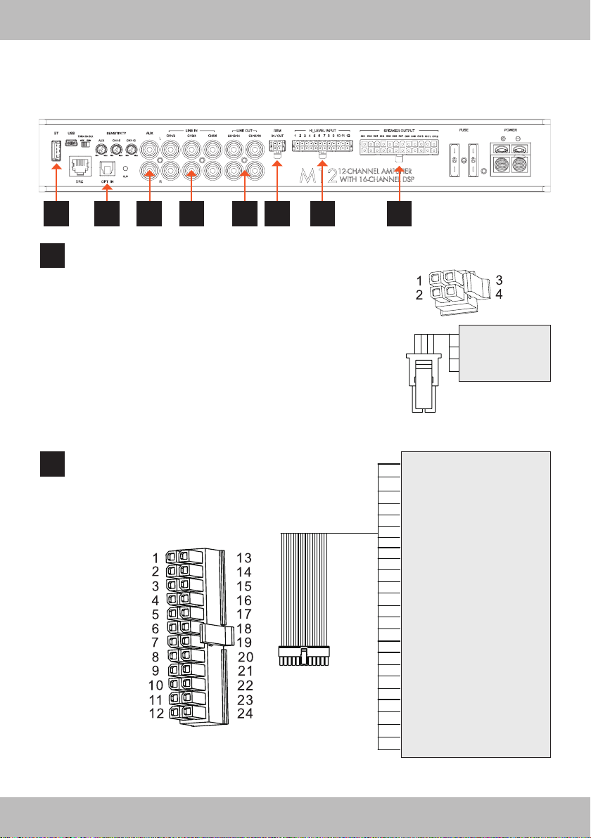
37910 6 8 4 5
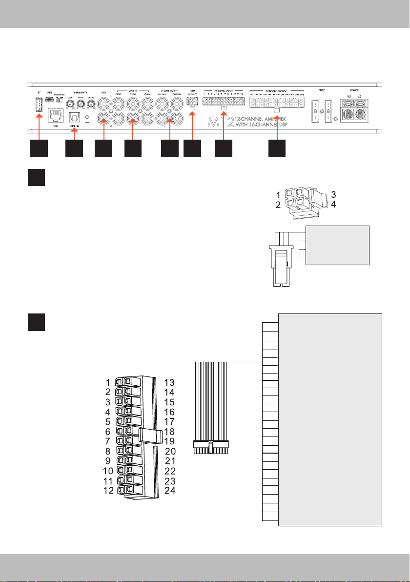
REM IN / OUT
3
REMOTE-IN is suited to turn on the M12 if a turn-on signal
from the head unit / car stereo is available. The voltage must
be between 7.5 and 16 VDC.
REMOTE-OUT is suited to turn on external ampliers. The
200 mA output current capability can also drive an auto-mo-
tive relay.
REVERSE SIG-IN is suited to switch the M12 from Bluetooth
mode to car host mode if the reverse gear is engaged. This
means that the audio signals from the parking sensors can be
heard through the sound system. Connect the +12 V reverse
gear signal or power supply for the reversing light here.
GND (Ground) must be connected with a suitable contact
ground point on the vehicle’s chassis
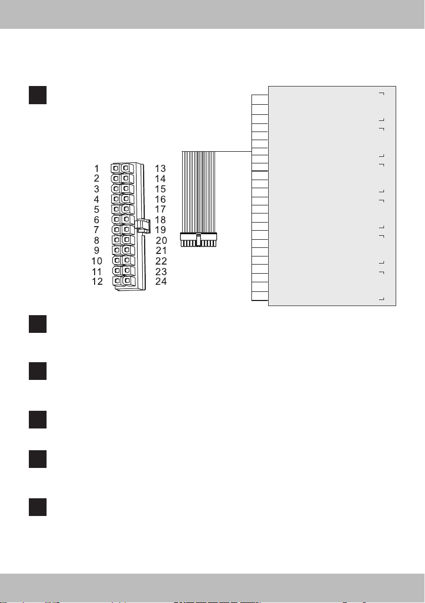
HI LEVEL INPUT
4
Input for the enclosed 24-pole cable adapter. Connect the
speaker outputs from your head unit / car stereo to the cable
adapter accordingly. The inputs can manage 8 - 24 V RMS.
FRONT VIEW
IMPORTANT NOTE:
CH1 features the Auto Turn-On function.
FRONT VIEW
GND
1:
REMOTE-OUT
®
2:
REVERSE SIG-IN
3:
REMOTE-IN
4:
HIGH LEVEL INPUT 1 +
1:
HIGH LEVEL INPUT 1 –
13:
HIGH LEVEL INPUT 2 +
2:
HIGH LEVEL INPUT 2 –
14:
HIGH LEVEL INPUT 3 +
3:
HIGH LEVEL INPUT 3 –
15:
HIGH LEVEL INPUT 4 +
4:
HIGH LEVEL INPUT 4 –
16:
HIGH LEVEL INPUT 5 +
5:
HIGH LEVEL INPUT 5 –
17:
HIGH LEVEL INPUT 6 +
6:
HIGH LEVEL INPUT 6 –
18:
HIGH LEVEL INPUT 7 +
7:
HIGH LEVEL INPUT 7 –
19:
HIGH LEVEL INPUT 8 +
8:
HIGH LEVEL INPUT 8 –
20:
HIGH LEVEL INPUT 9 +
9:
HIGH LEVEL INPUT 9 –
21:
HIGH LEVEL INPUT 10 +
10:
HIGH LEVEL INPUT 10 –
22:
HIGH LEVEL INPUT 11 +
11:
HIGH LEVEL INPUT 11 –
23:
HIGH LEVEL INPUT 12 +
12:
HIGH LEVEL INPUT 12 –
24:
8
Page 9
INTERCONNECTION
ENGLISH
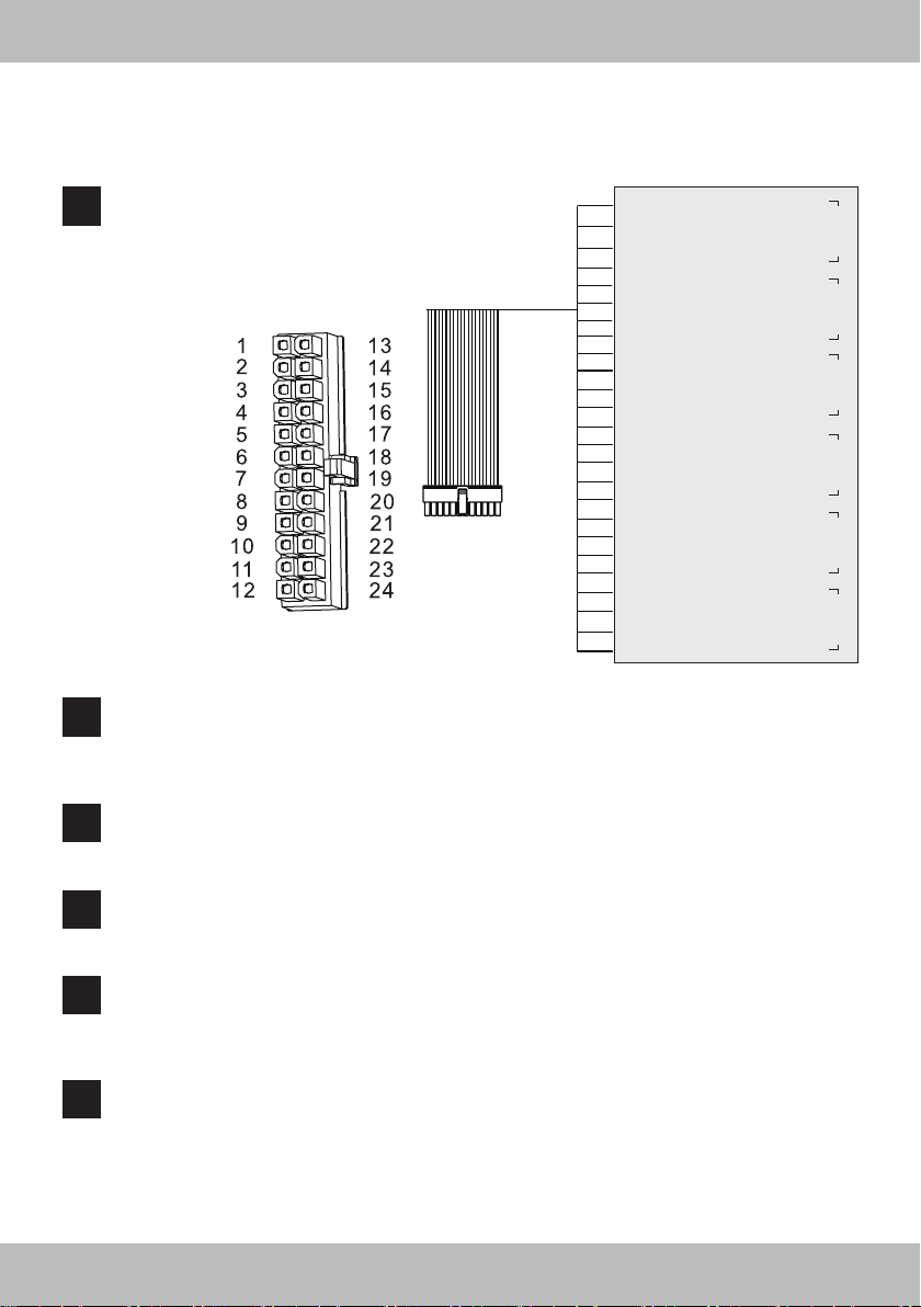
SPEAKER OUTPUT
5
The speaker outputs are amplied and can be operated in
BLT mode (bridged). It is recommended to connect here a
passive subwoofer bridged (4 Ohms) or an speaker pair
(2 - 4 Ohms) for each channel pair.
FRONT VIEW
LINE IN CH1- 6 (low level inputs):
6
If you want to use the signal input section with low level signals (e.g. with the pre-amplier outputs
SPEAKER OUTPUT 1 +
1:
SPEAKER OUTPUT 1 –
13:
SPEAKER OUTPUT 2 +
2:
SPEAKER OUTPUT 2 –
14:
SPEAKER OUTPUT 3 +
3:
SPEAKER OUTPUT 3 –
15:
SPEAKER OUTPUT 4 +
4:
SPEAKER OUTPUT 4 –
16:
SPEAKER OUTPUT 5 +
5:
SPEAKER OUTPUT 5 –
17:
SPEAKER OUTPUT 6 +
6:
SPEAKER OUTPUT 6 –
18:
SPEAKER OUTPUT 7 +
7:
SPEAKER OUTPUT 7 –
19:
SPEAKER OUTPUT 8 +
8:
SPEAKER OUTPUT 8 –
20:
SPEAKER OUTPUT 9 +
9:
SPEAKER OUTPUT 9 –
21:
SPEAKER OUTPUT 10 +
10:
SPEAKER OUTPUT 10 –
22:
SPEAKER OUTPUT 11 +
11:
SPEAKER OUTPUT 11 –
23:
SPEAKER OUTPUT 12 +
12:
SPEAKER OUTPUT 12 –
24:
from your head unit / car stereo), connect here the RCA plugs accordingly. The inputs can manage
2 - 6 V RMS.
AUX
7
These stereo RCA inputs are suited for an auxiliary low level input signal from an external stereo
pre-amplier source such as a game console or a media player. The inputs can manage 1 - 8 V RMS.
BRIDGED BRIDGED BRIDGED BRIDGED BRIDGED BRIDGED
LINE OUT CH13/14 & CH15/16 (processed by DSP)
8
Use the pre-amplier RCA outputs for driving an additional amplier or an active powered subwoofer.
The outputs deliver 5 V RMS Max.
OPT IN
9
The amplier accepts through its Optical input PCM stereo signals up to 192 kHz / 24 bit sampling
frequency rate. Multi-channel signals coming from audio/video sources (such as the audio tracks of a
lm in DVD) can not be reproduced. Connect a ber optic cable with a TOSLINK connector.
BT
10
This USB input is suited for an external MUSWAY Bluetooth® dongle with wireless audio streaming
function with/or adjusting the DSP by an APP through a smart phone/mobile device. The compatible
dongles are BTS, BTS-HD and BTA2. Check the website “www.musway.de” for more information or
ask your car audio retailer.
9
Page 10
ENGLISH
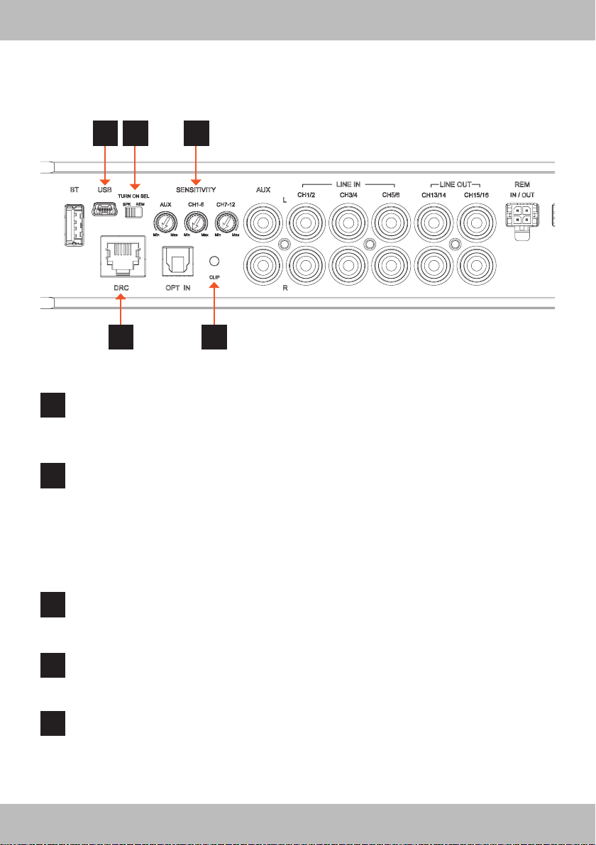
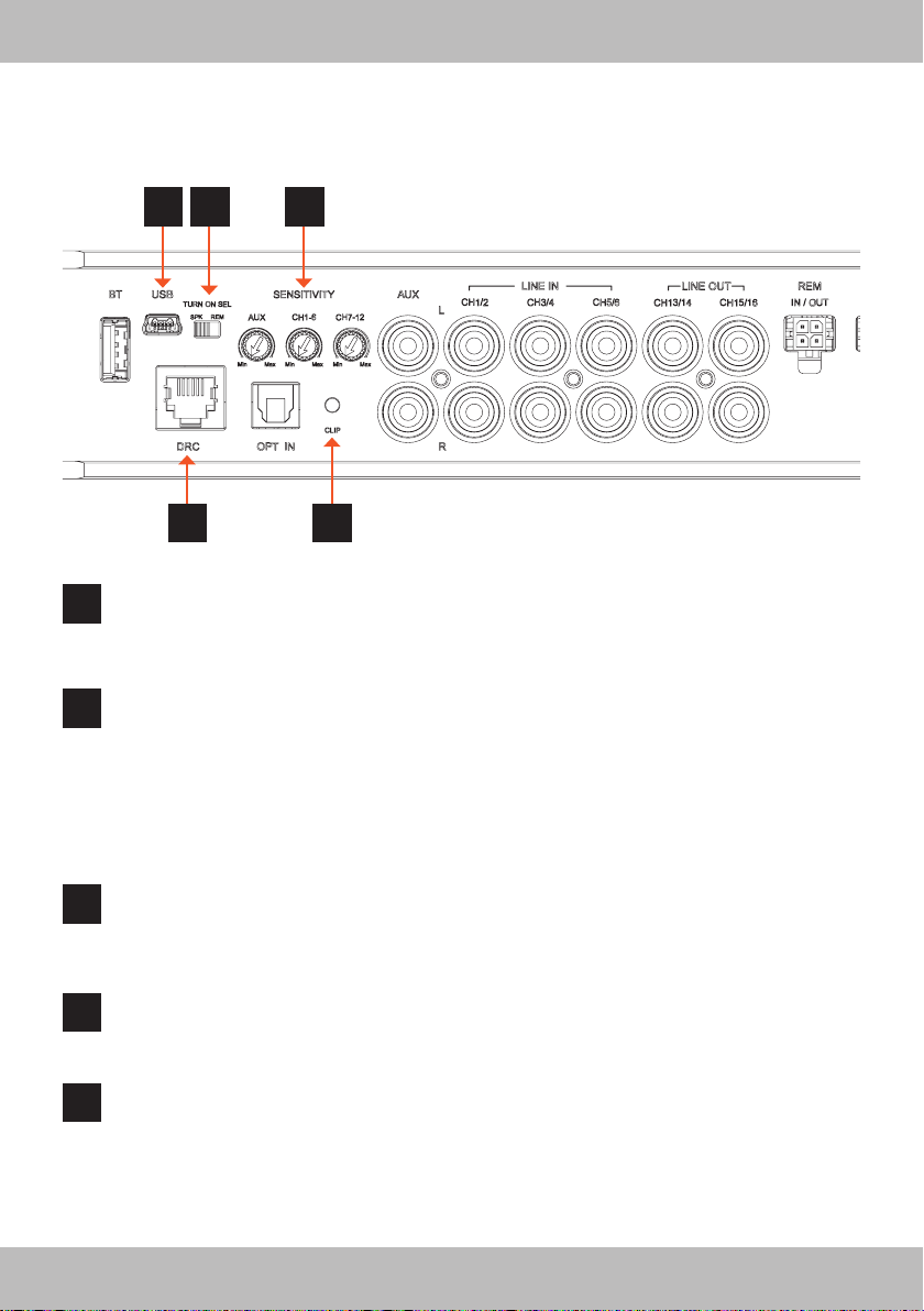
FUNCTIONAL CONTROLS
11 12 13
14
USB
11
This USB input is suited for the connection with a PC/laptop computer, where the MUSWAY DSP V3.x
software is installed. The connection is USB 1.1/2.0/3.0 compatible. For downloading the software
please visit “www.musway.de/dsp”.
TURN ON SEL
12
The amplier can be turned on/off by using the following methods:
SPK: Slide the switch into position SPK, if you want to turn on/off the amplier through
the CH1 input channel of the high level speaker inputs and its Auto Turn-On function.
Refer to page 8 and section 4 for more details.
REM: Slide the switch into position REM, if you want to turn on/off the amplier through
the REM and a turn-on signal from head unit / car stereo.
Refer to page 8 and section 3 for more details.
SENSITIVITY AUX, CH1-6 & CH7-12
13
With these controllers you can adjust the input sensitivity for each input section separately. This function is suited to match the output voltage of the connected signal source with the amplier.
DRC
14
This input is suited for the external MUSWAY DRC1 digital remote controller. Check the website
“www.musway.de” for more information or ask your car audio retailer.
CLIP
15
This LED lights up red if one of the high level inputs (CH1-6 & CH7-12) is overdriven. The LED has no
function when an input signal is applied to the Optical input and the Bluetooth® input. If this LED lights
up, reduce the input sensitivity by using the regarding “Sensitivity“ controller until the LED goes out.
15
10
Page 11
ENGLISH
SYSTEM CONFIGURATION
In order to congure the inputs, amplied speaker outputs and pre-amplied power outputs, EQ and time
delays for the amplier, it must be interfaced with the PC. When you get to this point you must already be
aware of what type of system you intend to set up. In order to avoid complications in preparation, make sure
the following points before you start:
• The type of signals that will be assigned to the inputs (e.g.: front left or center or subwoofer, etc.).
• The speakers in the system (e.g.: 3-way front or sub stereo or 2-way rear, etc.).
• If there are passive crossovers that manage groups of speakers (e.g.: 3-way systems with active
midrange).
• If you intend to use an external mono amplier to drive a subwoofer.
• If you intend to use the amplied outputs of the amplier bridged (BLT mode), thus increasing the power on
the output.
INITIAL SYSTEM START-UP
• Download and save the MUSWAY DSP V3.x software via “www.musway.de/dsp” before connecting the
amplier to your personal computer.
• Install the amplier in your vehicle before you connect a computer to it.
• Turn the ignition key to the ACC or ON position.
• Connect a PC/Laptop with the USB terminal of amplier by using the enclosed USB cable.
• After you have open the DSP software, you can set/adjust all the audio settings on the computer.
• The amplier is on when the logo on the top lights up in orange. After 10 seconds it becomes operative.
WARNING
Before turning on the system, set the head-unit output level to a lower level (approximately
20% of its maximum excursion) to avoid damaging the speakers during calibration.
Check again carefully the conguration of the crossovers , the speakers setup. Wrong type
of crossover or inappropriate parameter may cause permanent damages on the speakers,
especially tweeters without passive crossovers.
11
Page 12
ENGLISH
TROUBLE SHOOTING
ATTENTION: All instructions in this troubleshooting refer to the entire sound system and its individual components.
The features of your device may not match the functions described in the notes. Then skip this point and move on to
the next one.
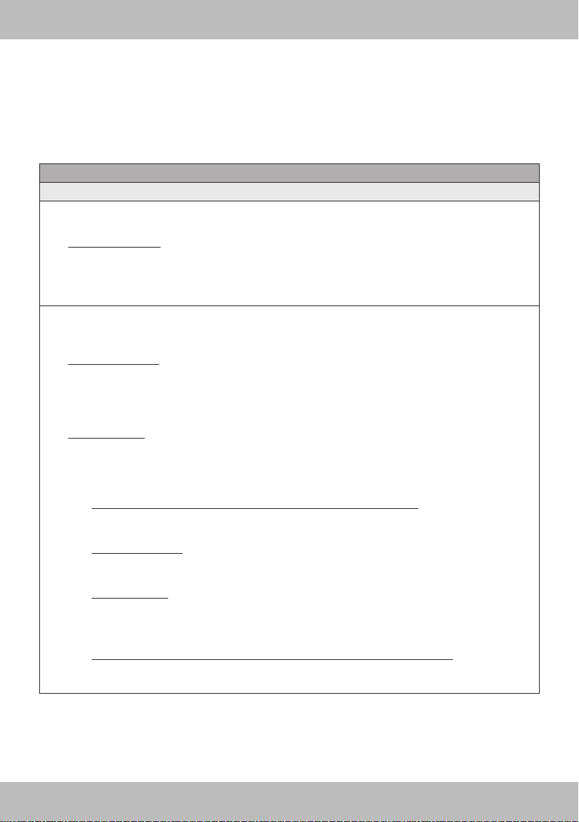
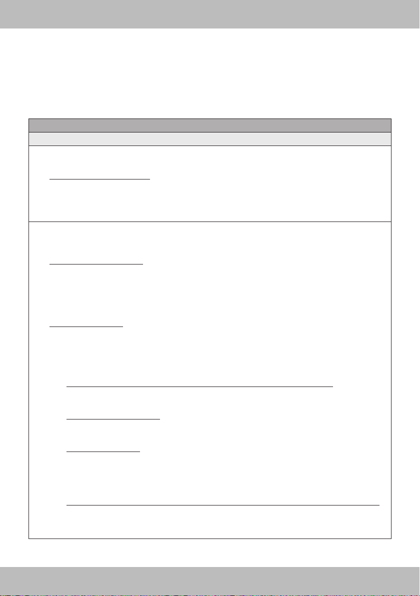
NO FUNCTION / THE POWER LED IS NOT ILLUMINATED
First check the fuse of the routed power cable on the vehicle battery
The fuse is defective
Replace the defective fuse with an equivalent one, never with a higher value.
• The fuse fails again.
In this case there appears to be a short circuit between the fuse and the amplier. To do this, check
the + 12V power cable along its entire length from the battery to the amplier for damage and whether
there is a short circuit to ground, e.g. a contact with the vehicle chassis or the body. If necessary,
replace the defective power cable.
The fuse is apparently okay
Use a standard 12 volt voltmeter to check the voltage between the + 12V connection and the ground
connection on the amplier.
• There is no voltage.
Use the voltmeter to check the fuse, which is located close to the vehicle battery, to see whether there
is voltage between the output and ground.
If there is no voltage there, either the fuse holder or the fuse is defective, although it appears to be
okay. If necessary, replace the fuse holder or fuse.
• There is voltage.
If you operate the amplier with a pre-amplier signal (RCA), you must have laid a remote turn-on
wire from the head unit to the REM terminal of the amplier. The AUTO TURN-ON switch must be in
the OFF position. However, you can test the AUTO TURN-ON switch to SIG. to see if the amplier
then turns on. If so, there is a problem with the control line..
• A remote turn-on wire is connected to the REM terminal at the amplier.
Use the voltmeter to check whether there is voltage between the REM terminal of the amplier and
ground. The head unit must be switched on.
There is no voltage.
• Check the remote turn-on wire from the amplier to the head unit for a short circuit or damage.
If necessary, replace the control line..
There is voltage.
• The amplier is probably malfunctioning or defective. Contact your retailer.
If you operate the amplier with the loudspeaker signals (high level mode), the AUTO TURN-ON
switch must be switched to DC.
• The AUTO TURN-ON switch is in the DC position, but the amplier remains off.
Check the speaker cables from the head unit to the amplier for short circuits or damage. If
necessary, replace the speaker cables or insulate the damaged area.
12
Page 13
ENGLISH
TROUBLE SHOOTING
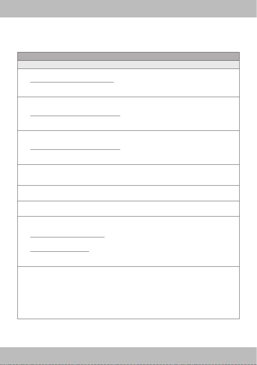
THE POWER LED IS ON, BUT NO SOUND COMES FROM THE SPEAKERS
Check the following steps:
Low level mode: Are the RCA cables on the head unit and on the amplier correctly connected?
• The RCA cables are correctly connected.
Then an RCA cables could be defective. Check the function of the RCA cables on another audio
device. If necessary, replace the defective RCA cables.
High level mode: Are the loudspeaker cables on the head unit and the high level inputs of the am-
plier or on the high level cable plug correctly connected?
• The speaker cables are connected correctly.
A speaker cable could be defective. If necessary, replace the speaker cable or insulate the damaged
area.
Are the speaker cables correctly connected between the speakers or the subwoofer at the speaker
outputs of the amplier?
• The speaker cables are connected correctly.
A speaker cable could be defective. If necessary, replace the speaker cable or insulate the damaged
area.
Is the high pass lter or subsonic lter set higher than the low pass lter on the amplier?
Then slowly turn down the controller for the high pass lter or subsonic lter until the sound can be
heard.
Is the input mode switch on the amplier set correctly?
Check the setting and change the switch position if necessary.
Are the crossover switches on the amplier set correctly?
Check the settings and change the respective switch position if necessary.
Are the speakers or the subwoofer working?
Hold a standard 9 volt block battery to the terminals of each loudspeaker or the subwoofer.
• A faint cracking sound can be heard.
The speaker or subwoofer is ne.
• There is nothing to be heard.
The loudspeaker or subwoofer could be defective. If necessary, replace the defective speaker or
subwoofer.
Are the settings on the head unit set correctly?
• Check the fader and balance settings
• Check whether the mute function is activated
• Check whether a high pass or low pass lter is activated
• Check whether playback has been paused
• Check the source settings
• Check whether any existing subwoofer output is activated
13
Page 14

ENGLISH
TROUBLE SHOOTING
DISTORTION OR HISSING NOISE CAN BE HEARD FROM THE SPEAKERS
Check the following steps:
Is a input level controller on the amplier set too high?
Slowly turn the controller back until you hear a clean audio signal.
Is the Bass Boost controller on the amplier set too high?
Slowly turn the controller back until you hear a clean audio signal.
Is the loudness function on the head unit set too high?
Deactivate loudness or turn the loudness setting back until you can hear a clean audio signal.
Are the EQ and sound settings on the head unit set too high?
Turn down the settings for Treble, Middle and Bass or deactivate the equalizer until you can hear a
clean audio signal.
ENGINE SPEED DEPENDENT NOISE CAN BE HEARD FROM THE SPEAKERS
Check the following steps:
Have the RCA cables been laid separately from the power cable in the vehicle?
If necessary, lay the cables again and make sure that the audio cables are laid separately from the
power cable on the left and right in the vehicle.
Is the amplier’s ground connection correctly connected?
Make sure that the ground connection of the amplier is not connected directly to the negative pole of
the vehicle battery. Select a suitable ground point on the vehicle body for connection. If necessary, use
contact spray to improve the conductivity of the connections.
Is the conductivity of the ground cable from the vehicle battery to the body okay?
Make sure that the ground connection of the vehicle battery has a stable and conductive connection to
the body. If necessary, use contact spray to improve the conductivity of the connections.
AN ACTIVE OPERATED TWEETER IS DISTORTED OR CRACKED
CAUTION: Tweeters will be damaged if the frequencies are too low. Please note the manufacturer’s
information on which frequency setting is recommended. To be on the safe side, pause the play-
back of the head unit rst. Check the following steps:
Is the crossover mode switch of the relevant channel pair on the amplier set correctly?
Set the crossover mode switch to the high pass position (HP or HPF).
Is the high pass lter of the relevant channel pair set too low on the amplier?
First turn the high pass controller fully clockwise. Now start playback on the head unit. Then turn the
high pass controller slowly counter-clockwise until you can hear a clean sound from the tweeters and
produce a balanced sound together with the woofers/mid-range speakers. Make sure that the woofers/
mid-range speakers are set correctly with the respective high pass and low pass controllers.
14
Page 15

ENGLISH
TROUBLE SHOOTING
AMPLIFIER ACTIVATES THE PROTECTIVE CIRCUIT / THE PROTECT LED ILLUMINATES
Check the following steps:
Short circuit on the speaker cables
• First disconnect all speaker cables from the amplier. Use a multimeter to check the ohmic impedance
of each loudspeaker by measuring between its plus and minus lines. With standard loudspeakers the
value uctuates between 3 and 5 ohms. The values for low-resistance subwoofers can be lower.
• The measurement shows a resistance value of less than 0.5 Ohms
Then there is a short circuit. Remove the wiring of the affected loudspeaker at its connections. Now
use the multimeter to check the ohmic impedance directly at the loudspeaker connections by measuring between the plus and minus connections.
The measurement shows a resistance value of more than 0.5 Ohms
• The speaker is ne, so the speaker wire appears to be defective and causing a short circuit.
Replace the defective speaker cable.
The measurement shows a resistance value of less than 0.5 Ohms
• The speaker appears to be defective and is shorting out. Replace the defective speaker.
The load impedance of the loudspeakers or the subwoofer is too low
• Compare the ohmic impedance of the connected loudspeaker or subwoofer with the technical specications of the amplier. For example, if the amplier is only designed for 2 or 4 ohm operation, no
loudspeaker with less than 2 ohms may be connected.
The cross-section of the power cables is too small
• If the cable cross-section is too small, this leads to an increased ohmic resistance and thus to a voltage drop (voltage loss). This indicates that the amplier consumes more power. The increased power
consumption results in a signicantly higher heat development and the amplier switches to thermal
protection mode. Therefore, observe the recommended cable cross-sections in these instructions and, if
necessary, lay power cables with a larger cable cross-section.
The amplier is overheated
• The heat sink of each amplier requires sufcient air circulation to be able to dissipate the heat generated during operation. If necessary, change the installation position in favor of better cooling of the
amplier or ensure better air circulation at the installation location.
• Turn off the sound system and wait about half an hour for the amplier to cool down again. With very
hot outside temperatures and strong sunlight, enormous heat develops inside the vehicle. The amplier
then activates its thermal protection circuit to prevent damage. After cooling down, the amplier works
properly again.
ATTENTION: All instructions in this troubleshooting refer to the entire sound system and its individual components.
The features of your device may not match the functions described in the notes. Then skip this point and move on to
the next one.
15
Page 16
DEUTSCH
TECHNISCHE DATEN
STROMVERSORGUNG
Betriebsspannung: 8 - 15 VDC
Ruhestrom: 3,2 A
Ausgeschaltet: <0,1 mA
Remote IN Spannung: 7,5 - 15 VDC (1 mA)
Remote OUT Spannung: 11 - 15 VDC (200 mA)
Gerätesicherung: 40 A x 2
VERSTÄRKER
Klirrfaktor - THD (1 kHz @ 4 Ω, 90% Leistung): 0.05 %
Frequenzgang (-3 dB, 2 V RMS, 4Ω): 15 Hz - 22 kHz
Signalrauschabstand @ A gewichtet, 1 V, Max. Leistung: 95 dB A
Dämpfungsfaktor @ 1 kHz, 2 V RMS, 4 Ω: > 70
Eingangsempndlichkeit: 8 V - 24 V RMS (Hochpegel); 2 V - 6 V RMS (Niedrigpegel); 1 - 8 V RMS (AUX)
Eingangsimpedanz: 13 Ω (Hochpegel); 47 kΩ (Niedrigpegel)
Lastimpedanz (Minimum):
@12CH: 2 Ω
@Gebrückt : 4 Ω
AUSGANGSLEISTUNG (RMS) @ 14,4 VDC, 1% THD*:
@ 4 Ω: 85 W
@ 2 Ω: 120 W
Gebrückt @ 4 Ω: 240 W
SIGNALAUSGÄNGE
RCA/Cinch Vorverstärkerausgänge CH13/14 & CH15/16: 5 V RMS Max
* In typischen Mehrkanal-Anwendungen (2-/3-Wege System + Hecklautsprecher + Subwoofer)
Konformitätserklärung
Hiermit erklärt die Audio Design GmbH, dass das Gerät MUSWAY M12 der Richtlinie 2014/53/EU entspricht. Die vollständige Konformitätserklärung ist einzusehen unter www.musway.de/CE
16
Page 17

DEUTSCH
TECHNISCHE DATEN
DIGITALER SIGNAL PROZESSOR (64 bit, 295 MHz)
Frequenzweichen: Vollbereich / Hochpass / Tiefpass / Bandpass
Frequenzweichentyp/Flankensteilheit: Bessel / Butterworth / Linkwitz @ 6/12/18/24/30/36/42/48 dB
Frequenz: 1 Hz Schritte @ 20 Hz - 20 kHz
Phasenverschiebung: 0° / 180°
Ausgangsequalizer: 31-Band Parametrischer Equalizer: ±12 dB
Abstand Laufzeitkorrektur: 0 - 692 cm
Verzögerung Laufzeitkorrektur: 0 - 17 ms
Schritte Laufzeitkorrektur: 0,08 ms; 2,8 cm
Feineinstellung Laufzeitkorrektur: 0,02 ms; 0,7 cm
Presets/Speicherplätze (Lokal gepeichert): 6 Presets/Speicherplätze
ALLGEMEINE ANFORDERUNGEN
PC Verbindung Micro USB (1.1 / 2.0 / 3.0)
Software/PC Anforderungen: Microsoft Windows (32/64 bit):
XP, Vista, Windows 7, Windows 8, Windows 10
Grakkarte min. Auösung: 1024 x 768
Umgebungstemperaturbereich: 0 - 55 °C
GRÖSSE / GEWICHT
Größe ohne Montagehalter (mm): 340 x 48 x 171,5
Nettogewicht (kg): 3,2
LIEFERUMFANG
1 x M12 DSP Verstärker
1 x 1,5 m USB Kabel
1 x 24-poliger Kabelstecker (Hochpegeleingänge)
1 x 24-poliger Kabelstecker (Lautsprecherausgänge)
1 x 4-poliger Kabelstecker (REM IN/OUT)
4 x Montageplatte inkl. Schrauben
1 x Bedienungsanleitung (Englisch/Deutsch)
2 x 40 A Geräteersatzsicherung
1 x 3 mm Innensechskant-Winkelschraubendreher
17
Page 18

DEUTSCH
SICHERHEITSHINWEISE
DAS VON IHNEN ERWORBENE GERÄT IST NUR FÜR DEN BETRIEB AN EINEM 12-V-BORDNETZ EINES
FAHRZEUGS AUSGELEGT. Andernfalls besteht Feuergefahr, die Gefahr eines elektrischen Schlages oder
anderer Verletzungen.
BITTE KEINE BEDIENUNG DES SOUNDSYSTEMS AUSFÜHREN, WELCHE VOM SICHEREN LENKEN
DES FAHRZEUGS ABLENKEN KÖNNTE. Führen Sie keine Bedienungen aus, die Ihre Aufmerksamkeit län-
gere Zeit in Anspruch nehmen. Stoppen Sie besser das Fahrzeug an einer sicheren Stelle am Straßenrand,
bevor Sie solche Bedienungen ausführen. Andernfalls besteht Unfallgefahr.
DIE LAUTSTÄRKE NUR SO HOCH EINSTELLEN, DASS SIE WÄHREND DER FAHRT NOCH AUSSENGERÄUSCHE WAHRNEHMEN KÖNNEN. Hochleistungsaudiosysteme in Fahrzeugen, können den Schallpegel
eines “Live-Konzertes” erzeugen. Dauerhaft extrem lauter Musik ausgesetzt zu sein kann den Verlust des
Hörvermögens oder Hörschäden zur Folge haben. Das Hören von lauter Musik beim Autofahren kann Ihre
Wahrnehmung (Warnsignale) beeinträchtigen. Im Interesse der allgemeinen Sicherheit empfehlen wir das Musikhören beim Autofahren mit geringer Lautstärke. Andernfalls besteht Unfallgefahr.
LÜFTUNGSÖFFNUNGEN UND KÜHLKÖRPER NICHT ABDECKEN. Andernfalls kann es zu einem Wärmestau im Gerät kommen und es besteht Feuergefahr.
DAS GERÄT AUF KEINEN FALL ÖFFNEN. Andernfalls besteht Unfallgefahr, Feuergefahr oder die Gefahr
eines elektrischen Schlages. Das Öffnen des Gerätes hat auch einen Garantieverlust zur Folge.
SICHERUNGEN IMMER DURCH SOLCHE MIT DER RICHTIGEN AMPEREZAHL ERSETZEN. Andernfalls
besteht Feuergefahr oder die Gefahr eines elektrischen Schlages.
DAS GERÄT NICHT WEITERBENUTZEN, WENN EINE FEHLFUNKTION AUFTRITT, DIE NICHT VON IHNEN BEHOBEN WERDEN KANN. Beachten Sie dazu den Abschnitt FEHLERBEHEBUNG. Andernfalls kann
es zu Verletzungen oder Schäden am Gerät kommen. Geben Sie das Gerät zu Reparaturzwecken an einen
autorisierten Händler oder den nächsten Kundendienst.
DIE INSTALLATION EINES PUFFERKONDENSATORS MIT AUSREICHENDER KAPAZIÄT WIRD EMPFOHLEN. Hochleistungsverstärker verursachen sehr hohe Spannungsabfälle und benötigen eine sehr hohe
Stromstärke bei hoher Leistung. Um das Bordnetz des Fahrzeuges nicht übermäßig zu belasten, wird die
Installation eines Pufferkondensators (auch Pufferelko, Powercap oder Power Capacitor genannt) empfohlen,
der parallel zum Verstärker und zur Stromquelle als Puffer fungiert. Lassen Sie sich am besten im Car Audio
Fachhandel beraten.
VERKABELUNG UND EINBAU VON FACHPERSONAL AUSFÜHREN LASSEN. Die Verkabelung und der
Einbau dieses Gerätes erfordern technisches Geschick und Erfahrung. Zu Ihrer eigenen Sicherheit sollten Sie
Verkabelung und Einbau dem Händler überlassen, bei dem Sie das Gerät erworben haben.
VOR DER INSTALLATION DAS KABEL VOM MASSEPOL DER BATTERIE ABKLEMMEN. Bevor Sie mit
der Installation des Soundsystems beginnen, trennen Sie unbedingt den Massepol der Autobatterie ab, um
Kurzschlüsse und Stromschläge zu vermeiden.
WÄHLEN SIE EINEN GEEIGNETEN EINBAUORT. Suchen Sie einen geeigneten Einbauort für das Gerät, bei
dem ausreichend Raum für eine kühlende Luftzirkulation vorherrscht. Am besten geeignet sind Reserveradmulden und offene Bereiche im Kofferraum. Weniger geeignet sind Stauräume hinter der Seitenverkleidung
oder Bereiche unter den Fahrzeugsitzen.
DAS GERÄT NICHT AN STELLEN EINBAUEN, AN DENEN ES HOHER FEUCHTIGKEIT ODER STAUB
AUSGESETZT IST. Bauen Sie das Gerät so ein, dass es vor hoher Feuchtigkeit und Staub geschützt ist. Wenn
Feuchtigkeit oder Staub in das Gerät gelangen, kann es zu Betriebsstörungen kommen. Schäden am Gerät,
welche durch Feuchtigkeit hervorgerufen wurden, unter- liegen nicht der Garantie.
DAS GERÄT SOWIE ANDERE KOMPONENTEN DES SOUNDSYSTEMS AUSREICHEND BEFESTIGEN.
Andernfalls könnten sich die Geräte und Komponenten während der Fahrt lösen und als gefährliche Geschosse im Fahrgastraum Beschädigungen und Verletzungen hervorrufen.
18
Page 19

DEUTSCH
SICHERHEITSHINWEISE
BEIM BOHREN VON LÖCHERN, BESTEHENDE KOMPONENTEN, LEITUNGEN UND KABEL DES FAHRZEUGS NICHT BESCHÄDIGEN. Wenn Sie bei der Installation Löcher in das Fahrzeugchassis bohren, achten
Sie unbedingt darauf die Kraftstofeitungen, den Benzintank, elektrische Kabel und andere Leitungen nicht zu
beschädigen, zu berühren oder zu blockieren.
AUF KORREKTE ANSCHLÜSSE ACHTEN. Bei fehlerhaften Anschlüssen besteht Feuergefahr, Kurzschluss-
gefahr und es kann zu Schäden am Gerät kommen.
AUDIOKABEL UND STROMKABEL SOLLTEN NICHT ZUSAMMEN VERLEGT WERDEN. Bei der Installati-
on des Audiokabels zwischen dem Cinch-Ausgang des Autoradios und dem Cinch-Eingang des Verstärkers im
Fahrzeug ist darauf zu achten, dass das Audio- und das Stromversorgungskabel möglichst nicht auf der selben
Seite des Fahrzeugs verlegt werden. Besser ist eine räumlich getrennte Installation, im rechten und linken Kabelschacht des Fahrzeugs. Damit wird das Überlagern von Störungen auf das Audio-Signal verringert. Dieses
gilt ebenfalls für das Verbindungskabel der beiliegenden Kabel-Fernbedienung. Das Kabel sollte nicht auf der
Seite der Stromversorgungsleitung verlegt werden, sondern zusammen mit den Audiokabeln.
SORGEN SIE DAFÜR, DASS SICH DIE KABEL NICHT IN GEGENSTÄNDEN IN DER NÄHE VERFANGEN.
Verlegen Sie die Kabel wie auf den folgenden Seiten beschrieben, damit diese beim Fahren nicht hinderlich
sind. Kabel die sich im Bereich des Lenkrads, des Schalthebels oder im Bremspedal usw. verfangen können,
führen zu äußerst gefährlichen Situationen.
ELEKTRISCHE KABEL NICHT SPLEISSEN. Kabel dürfen nicht abisoliert werden, um andere Geräte mit
Strom zu versorgen. Andernfalls wird die Strombelastbarkeit des Kabels überschritten, und es besteht Feuergefahr oder die Gefahr eines elektrischen Schlages. Verwenden Sie hierfür am besten geeignete Verteilerblöcke.
BOLZEN UND MUTTERN DER BREMSANLAGE NICHT ALS MASSEPUNKT VERWENDEN. Verwenden
Sie für den Einbau oder Masseanschluss keine Bolzen oder Muttern der Brems- bzw. Lenkanlage oder eines
anderen sicherheitsrelevanten Systems. Andernfalls besteht Feuergefahr oder die Fahrsicherheit ist beein-
trächtigt.
DIE KABEL SO VERLEGEN, DASS SIE NICHT GEKNICKT ODER DURCH SCHARFE KANTEN GEQUETSCHT WERDEN. Verlegen Sie die Kabel so, dass sie sich nicht in beweglichen Teilen wie den Sitzschie-
nen vefangen oder an scharfen Kanten oder spitzen Ecken beschädigt werden können. Wenn Sie ein Kabel
durch eine Bohrung in einer Metallplatte führen, schützen Sie die Kabelisolierung mit einer Gummitülle vor
Beschädigungen durch Metallkanten der Bohrung.
KLEINTEILE WIE SCHRAUBEN UND ANSCHLUSS-STECKER VON KINDERN FERNHALTEN. Werden
solche Gegenstände verschluckt, besteht die Gefahr schwerwiegender Verletzungen. Suchen Sie unverzüglich einen Arzt auf, sollte ein Kind einen solchen Gegenstand verschluckt haben.
10 ~ 90% 5 ~ 50°C
19
Page 20
DEUTSCH
MECHANISCHE INSTALLATION
• Achten Sie bei der Installation darauf, dass keine serienmäßig im KFZ vorhandenen Teile wie z.B. Kabel,
Bordcomputer, Sicherheitsgurte, Tank oder ähnliche Teile beschädigt bzw.entfernt werden.
• Vergewissern Sie sich, dass der Verstärker am Montageort genügend Kühlung erhält. Montieren Sie das
Gerät nicht in zu kleine, abgeschlossene Gehäuse ohne Luftzirkulation, in die Nähe von wärmeabstrahlende
Teilen oder elektronischen Steuerungen des Fahrzeuges.
• Montieren Sie den Verstärker auf keinen Fall auf ein Bassgehäuse oder andere vibrierende Teile, dadurch
können sich die Bauteile im Inneren losvibrieren und das Gerät ernsthaft beschädigen.
• Die Kabel der Stromversorgung und die Audiosignalkabel sollten bei dem Einbau so kurz als möglich gehal-
ten werden, um Verluste und Störungen zu vermeiden.
ACHTUNG
Bevor Sie mit der Installation des Soundsystems beginnen, trennen Sie unbedingt den
Massepol der Fahrzeugbatterie ab, um Kurzschlüsse und Stromschläge zu vermeiden.
20
Page 21
ANSCHLUSS
VOR DEM ANSCHLIESSEN
Für den fachgerechten Anschluss des Soundsystems sind geeignete Kabelsets im Fachhandel erhältlich. Achten Sie beim Kauf auf
einen ausreichenden Kabelquerschnitt (siehe Tabelle unten), den
passenden Sicherungswert sowie auf die Leitfähigkeit der Kabel.
Säubern und entfernen Sie vorhandene Rost- und Oxidationsstellen an allen Kontaktpunkten der Batterie und an den Massepunkten.
Ziehen Sie nach der Installation alle Schrauben fest an, denn ein
lockerer Anschluss kann eine Fehlfunktion, unzureichende Stromversorgung oder Störgeräusche sowie Verzerrungen verursachen.
FUSE
1
Die integrierten Stecksicherungen (2 x 40 A) schützen das Gerät vor Kurzschlüssen und Überlastung. Tauschen Sie eine defekte Sicherung nur gegen eine aus, die gleichen Typs ist und den
gleichen Sicherungswert besitzt.
POWER
2
Verbinden Sie den POWER + Anschluss mit dem 12 Volt Pluspol der Fahrzeugbatterie mit dem dafür
vorgesehen Kabel (siehe dazu die Tabelle unten).
Verbinden Sie den POWER – Anschluss mit einem geeigneten Massepunkt am Fahrzeugchassis. Das
Massekabel sollte möglichst kurz sein und an einem blanken, metallischen Punkt angebracht werden.
Achten Sie darauf, dass dieser Punkt eine sichere elektrische Verbindung zum Minuspol der Fahrzeugbatterie hat. Überprüfen Sie zudem die Masseleitung von der Batterie zur Karosserie und verstärken diese wenn nötig. Verwenden Sie zum Anschluss ein ausreichend dimensioniertes Massekabel (siehe dazu
die Tabelle unten). Der Querschnitt muss dabei genauso groß wie bei der Plusleitung gewählt werden.
ZUSÄTZLICHE KABELSICHERUNG (NICHT IM LIEFERUMFANG ENTHALTEN)
Installieren Sie eine zusätzliche Sicherung für das Stromkabel in der Nähe der Batterie. Der Abstand
zwischen Sicherung und Batterie sollte nicht mehr als 30 cm betragen. Die Sicherungsgröße muss
dem Kabelquerschnitt des verlegten Stromkabels angepasst sein (siehe Tabelle unten).
WICHTIG: Die Sicherung an der Batterie sichert nicht den Verstärker, sondern die Leitung zwischen
Batterie und Verstärker gegen Kurzschluss.
1
DEUTSCH
2
Kabellänge in m
Sicherungswert 0 - 1,2 1,2 - 2,1 2,1 - 3,1 3,1 - 4,0 4,0 - 4,9 4,9 - 5,8 5,8 - 6,7 6,7 - 8,5
20 - 35 A 4 6 10 10 16 16 16 20
35 - 50 A 6 10 10 16 16 20 20 20
50 - 65 A 10 10 16 20 20 20 20 35
65 - 85 A 16 16 20 20 35 35 35 50
85 - 105 A 16 16 20 35 35 35 35 50
105 - 125 A 20 20 20 35 35 50 50 50
Mindestkabelquerschnitt in mm
Empfohlener Mindestkabelquerschnitt um die volle Verstärkerleistung zu garantieren:
Bis 3 m Länge: 20 mm
Ab 3 m Länge: 25 mm2 / OFC Vollkupferkabel
Ersetzen Sie defekte Sicherungen nur durch eine gleichen Typs mit gleichem Sicherungswert.
2
/ OFC Vollkupferkabel
2
21
Page 22
DEUTSCH
ANSCHLUSS
37910 6 8 4 5
REM IN / OUT
3
REMOTE-IN ist geeignet, um den Verstärker einzuschalten wenn ein
Einschaltsignal vom Steuergerät/Autoradio verfügbar ist. Die Spannung muss zwischen 7,5 und 16 VDC liegen.
REMOTE-OUT ist geeignet, um z.B. einen weiteren Verstärker einzuschalten. Mit einer Ausgangsstromstärke von 200 mA kann auch ein
automatisches Relais angesteuert werden.
REVERSE SIG-IN ist geeignet, den M12 bei eingelegtem Rückwärts-
gang vom Bluetooth
®
-Modus in den Car-Host-Modus zu schalten.
Dadurch sind die Audiosignale der Parksensoren über das Soundsystem zu hören. Schließen Sie hier das +12-V-Rückfahrsignal oder
die Stromversorgung für den Rückfahrscheinwerfer an.
GND (Ground) muss mit einem geeigneten Massepunkt am Fahr-
zeugchassis verbunden werden
HI LEVEL INPUT
4
Eingang für den beiliegenden 24-poligen Kabeladapter. Verbinden Sie die Lautsprecherausgänge Ihres Steuergeräts/
Autoradios entsprechend mit dem Kabeladapter. Die Eingänge sind für 8 - 24 V RMS ausgelegt.
VORDERANSICHT
HINWEIS: In CH1 ist automatische
Einschaltfunktion (Auto-Turn-On) integriert.
VORDERANSICHT
GND
1:
REMOTE-OUT
2:
REVERSE SIG-IN
3:
REMOTE-IN
4:
HOCHPEGELEINGANG 1 +
1:
HOCHPEGELEINGANG 1 –
13:
HOCHPEGELEINGANG 2 +
2:
HOCHPEGELEINGANG 2 –
14:
HOCHPEGELEINGANG 3 +
3:
HOCHPEGELEINGANG 3 –
15:
HOCHPEGELEINGANG 4 +
4:
HOCHPEGELEINGANG 4 –
16:
HOCHPEGELEINGANG 5 +
5:
HOCHPEGELEINGANG 5 –
17:
HOCHPEGELEINGANG 6 +
6:
HOCHPEGELEINGANG 6 –
18:
HOCHPEGELEINGANG 7 +
7:
HOCHPEGELEINGANG 7 –
19:
HOCHPEGELEINGANG 8 +
8:
HOCHPEGELEINGANG 8 –
20:
HOCHPEGELEINGANG 9 +
9:
HOCHPEGELEINGANG 9 –
21:
HOCHPEGELEINGANG 10 +
10:
HOCHPEGELEINGANG 10 –
22:
HOCHPEGELEINGANG 11 +
11:
HOCHPEGELEINGANG 11 –
23:
HOCHPEGELEINGANG 12 +
12:
HOCHPEGELEINGANG 12 –
24:
22
Page 23
ANSCHLUSS
DEUTSCH
SPEAKER OUTPUT
5
Die Lautsprecherausgänge werden verstärkt und kön-
nen im BLT-Modus (gebrückt) betrieben werden. Es
wird empfohlen, hier für jedes Kanalpaar einen passiven Subwoofer gebrückt (4 Ohm) oder ein zusätzliches
Lautsprecherpaar (2 - 4 Ohm) anzuschließen.
VORDERANSICHT
LINE IN CH1- 6 (Niederpegeleingänge):
6
Wenn Sie die Eingangssektion mit Niederpegelsignalen verwenden möchten (z. B. mit den Vorver-
LAUTSPRECHERAUSGANG 1 +
1:
LAUTSPRECHERAUSGANG 1 –
13:
LAUTSPRECHERAUSGANG 2 +
2:
LAUTSPRECHERAUSGANG 2 –
14:
LAUTSPRECHERAUSGANG 3 +
3:
LAUTSPRECHERAUSGANG 3 –
15:
LAUTSPRECHERAUSGANG 4 +
4:
LAUTSPRECHERAUSGANG 4 –
16:
LAUTSPRECHERAUSGANG 5 +
5:
LAUTSPRECHERAUSGANG 5 –
17:
LAUTSPRECHERAUSGANG 6 +
6:
LAUTSPRECHERAUSGANG 6 –
18:
LAUTSPRECHERAUSGANG 7 +
7:
LAUTSPRECHERAUSGANG 7 –
19:
LAUTSPRECHERAUSGANG 8 +
8:
LAUTSPRECHERAUSGANG 8 –
20:
LAUTSPRECHERAUSGANG 9 +
9:
LAUTSPRECHERAUSGANG 9 –
21:
LAUTSPRECHERAUSGANG 10 +
10:
LAUTSPRECHERAUSGANG 10 –
22:
LAUTSPRECHERAUSGANG 11 +
11:
LAUTSPRECHERAUSGANG 11 –
23:
LAUTSPRECHERAUSGANG 12 +
12:
LAUTSPRECHERAUSGANG 12 –
24:
stärkerausgängen Ihres Steuergeräts/Autoradios), schließen Sie hier die Cinch-Stecker entspre-
chend an. Die Eingänge sind für 2 - 6 V RMS ausgelegt.
AUX
7
Diese Stereo-Cinch-Eingänge eignen sich für ein zusätzliches Niederpegelsignal von einer externen
Stereoquelle wie von einer Spielekonsole oder einem Mediaplayer. Die Eingänge sind für 1 - 8 V RMS
ausgelegt
GEBRÜCKT GEBRÜCKT GEBRÜCKT GEBRÜCKT GEBRÜCKT GEBRÜCKT
LINE OUT CH13/14 & CH15/16 (DSP prozessiert)
8
Verwenden Sie die Vorverstärker-Cinch-Ausgänge zum Ansteuern eines zusätzlichen Verstärkers
oder eines aktiven Subwoofers. Die Ausgänge liefern max. 5 V RMS.
OPT IN
9
Der Verstärker akzeptiert über seinen optischen Eingang PCM-Stereosignale (192 kHz / 24 Bit). Mehrkanalsignale von Audio-/Videoquellen (z. B. die Audiospuren eines Films auf DVD) können nicht wie-
dergegeben werden. Schließen Sie ein Glasfaserkabel mit einem TOSLINK-Anschluss an.
BT
10
Dieser USB-Eingang ist für externen MUSWAY Bluetooth® Dongle mit drahtloser Audio-StreamingFunktion mit/oder Anpassung des DSP über die APP mit einem Smartphone/Mobilgerät. Die kompatiblen Dongles sind BTS, BTS-HD and BTA2. Informieren Sie sich unter „www.musway.de“ oder
fragen Sie Ihren Fachhändler.
23
Page 24
DEUTSCH
FUNKTIONSBESCHREIBUNG
11 12 13
14
USB
11
Dieser USB-Eingang ist für die Verbindung mit einem PC/Laptop-Computer geeignet, auf dem die
MUSWAY DSP V3.x Software installiert ist. Die Verbindung ist USB 1.1 / 2.0 / 3.0 kompatibel. Zum
Herunterladen der Software besuchen Sie bitte „www.musway.de/dsp“.
TURN ON SEL (Einschaltauswahl)
12
Der Verstärker kann mithilfe der folgenden Methoden ein- und ausgeschaltet werden:
SPK: Schieben Sie den Schalter in Position SPK, wenn Sie den Verstärker über CH1 und
dessen automatische Einschaltfunktion ein-/ausschalten möchten. Weitere Informationen
nden Sie auf Seite 22 und Abschnitt 4.
REM: Schieben Sie den Schalter in Position REM, wenn Sie den Verstärker über REM und das
Einschaltsignal vom Autoradio ein-/ausschalten möchten. Weitere Informationen nden
Sie auf Seite 22 und Abschnitt 3.
SENSITIVITY AUX, CH1-6 & CH7-12
13
Mit diesen Reglern können Sie die Eingangsempndlichkeit für die analogen Eingänge einstellen.
Diese Funktion ist geeignet, um die Ausgangsspannung der angeschlossenen Signalquelle an den
Verstärker anzupassen.
DRC
14
Dieser Eingang ist für die externe digitale Fernbedienung MUSWAY DRC1 geeignet. Auf der Website
„www.musway.de“ nden Sie weitere Informationen oder fragen Sie Ihren Fachändler.
CLIP
15
Diese LED leuchtet rot wenn einer der Hochpegeleingänge (CH1-6 & CH7-12) übersteuert ist. Die
LED hat keine Funktion am optischen Eingang und Bluetooth-Eingang. Wenn diese LED leuchtet,
verringern Sie die Eingangsempndlichkeit, indem Sie den entsprechenden Regler unter „Sensitivity“
zurückdrehen bis die LED erlischt.
15
24
Page 25
DEUTSCH
SYSTEMKONFIGURATION
Um sämtliche Ein- und Ausgänge, den EQ und Laufzeitkorrektur für den Verstärker zu kongurieren, muss
eine Verbindung mit einem PC/Laptop hergestellt werden. Wenn Sie an diesen Punkt kommen, müssen Sie
bereits wissen, welche Art von System Sie einrichten möchten. Um Komplikationen bei der Vorbereitung zu
vermeiden, legen Sie folgende Punkte fest bevor Sie beginnen:
• Die Art der Signale, die den Eingängen zugewiesen werden (z. B. vorne links oder Mitte oder Subwoofer
usw.).
• Die Belegung der Lautsprecher im System (z. B. 3-Wege-Front oder Sub-Stereo oder 2-Wege-Rückseite,
etc.).
• Ob eine passive Frequenzweichenschaltung verwendet wird, (z. B. 3-Wege-Systeme mit aktivem
Mitteltöner).
• Ob Sie einen externen Monoverstärker zum Ansteuern eines Subwoofers verwenden möchten.
• Ob Sie beabsichtigen, die verstärkten Ausgänge des Verstärkers zu brücken (BLT-Modus), denn dadurch
erhöht sich die Leistung am Ausgang.
ERSTER SYSTEM START
• Laden und speichern Sie die MUSWAY DSP V3.x Software unter bitte „www.musway.de/dsp“, bevor Sie
den Verstärker an Ihren PC anschließen.
• Installieren Sie den Verstärker in Ihrem Fahrzeug, bevor Sie einen Computer an ihn anschließen.
• Den Zündschlüssel in die Stellung ACC oder ON drehen.
• Schließen Sie einen PC/Laptop über das mitgelieferte USB-Kabel an den Verstärkers an.
• Nachdem Sie die DSP-Software geöffnet haben, können Sie alle Einstellungen am Computer anpassen.
• Der Verstärker ist eingeschaltet, wenn das Logo auf der Oberseite orange leuchtet. Nach etwas 10 Sekun-
den ist der Verstärker samt DSP steuerbar.
ACHTUNG
Bevor Sie das System einschalten, stellen Sie den Ausgangspegel des Autoradios auf einen niedrigeren Pegel ein (ca. 20% der maximalen Auslenkung), um eine Beschädigung der
Lautsprecher während der Konguration zu vermeiden.
Bevor Sie das Soundsystem einschalten, überprüfen Sie nochmals sorgfältig die Kongura-
tion der Frequenzweichen und Lautsprecher. Eine falsch eingestellte Frequenzweiche oder
ungeeignete Parameter können zu dauerhaften Schäden an den Lautsprechern führen, insbesondere an Hochtönern ohne passive Frequenzweichen.
25
Page 26
DEUTSCH
FEHLERBEHEBUNG
ACHTUNG: Sämtliche Hinweise dieser Fehlerbehebung beziehen sich auf das gesamte Soundsystem und deren Ein-
zelkomponenten. Unter Umständen entspricht die Ausstattung Ihres Geräts nicht den in den Hinweisen beschriebenen
Funktionen. Überspringen Sie dann diesen Punkt und machen mit dem nächsten weiter.
KEINE FUNKTION / DIE POWER LED LEUCHTET NICHT
Überprüfen Sie zuerst die Sicherung des verlegten Stromkabels an der Fahrzeugbatterie
Die Sicherung ist defekt
Ersetzen Sie die defekte Sicherung mit einer gleichwertigen, keinesfalls mit einem höheren Wert.
• Die Sicherung fällt erneut aus.
In diesem Fall scheint ein Kurzschluss zwischen Sicherung und Verstärker vorzuliegen. Überprüfen
Sie dazu das +12V Stromkabel auf ganzer Länge von der Batterie bis zum Verstärker auf Beschädigungen und ob ein Kurzschluss mit Masse vorliegt, z.B. ein Kontakt zum Fahrzeugchassis oder der
Karosserie. Ersetzen Sie gegebenenfalls das defekte Stromkabel.
Die Sicherung ist augenscheinlich in Ordnung
Überprüfen Sie mithilfe eines handelsüblichen 12 Volt Spannungsmessers die Spannung zwischen dem
+12V Anschluss und dem Masseanschluss am Verstärker.
• Es liegt keine Spannung an.
Überprüfen Sie mithilfe des Spannungsmessers die Sicherung, die in der Nähe an der Fahrzeugbat-
terie bendet, ob dort zwischen dem Ausgang und Masse Spannung anliegt.
Liegt dort keine Spannung an, ist entweder der Sicherungshalter oder doch die Sicherung defekt,
obwohl diese in Ordnung zu sein scheint. Ersetzen Sie gegebenenfalls den Sicherungshalter oder die
Sicherung.
• Es liegt Spannung an.
Wenn Sie den Verstärker mit einem Vorverstärkersignal (Cinch/RCA) betreiben, müssen Sie eine
Steuerleitung (REM) vom Autoradio/Steuergerät zum REM Anschluss des Verstärker gelegt haben.
Der AUTO TURN-ON Schalter muss sich hierbei in Schalterstellung OFF benden. Sie können jedoch
testweise den AUTO TURN-ON Schalter auf SIG. stellen, um zu sehen ob sich der Verstärker dann
einschaltet. Ist dies der Fall, liegt ein Problem mit der Steuerleitung vor.
• Eine Steuerleitung (REM) ist am REM Anschluss des Verstärker angeschlossen.
Überprüfen Sie mithilfe des Spannungsmessers, ob zwischen dem REM Anschluss des Verstär-
kers und Masse eine Spannung anliegt. Dabei muss das Autoradio/Steuergerät angeschaltet sein.
Es liegt keine Spannung an.
• Überprüfen Sie die Steuerleitung vom Verstärker zum Autoradio/Steuergerät auf einen Kurz-
schluss oder eine Beschädigung. Ersetzen Sie gegebenenfalls die Steuerleitung.
Es liegt Spannung an.
• Der Verstärker hat wahrscheinlich eine Fehlfunktion oder ist defekt. Kontaktieren Sie Ihren
Fachhändler.
Wenn Sie den Verstärker mit den Lautsprechersignalen (Hochpegel/High Level) betreiben, muss der
AUTO TURN-ON Schalter auf DC umgeschaltet sein.
• Der AUTO TURN-ON Schalter bendet sich in Position DC, dennoch bleibt der Verstärker aus.
Überprüfen Sie die Lautsprecherkabel vom Autoradio/Steuergerät zum Verstärker auf Kurzschlüsse oder Beschädigungen. Ersetzen Sie gegebenenfalls die Lautsprecherkabel oder
isolieren Sie die beschädigte Stelle.
26
Page 27
DEUTSCH
FEHLERBEHEBUNG
DIE POWER LED LEUCHTET, ABER ES KOMMT KEIN TON AUS DEN LAUTSPRECHERN
Überprüfen Sie folgende Schritte:
Niederpegelmodus: Sind die RCA/Cinchkabel am Radio/Steuergerät und am Verstärker korrekt
angeschlossen?
• Die RCA/Cinchkabel sind korrekt angeschlossen.
Es könnte ein RCA/Cinchkabel defekt sein. Überprüfen Sie die Funktion der RCA/Cinchkabel an
einem anderen Audiogerät. Ersetzen Sie gegebenenfalls das defekte RCA/Cinchkabel.
Hochpegelmodus: Sind die Lautsprecherkabel am Radio/Steuergerät und den Hochpegel-Eingän-
gen des Verstärker bzw. am Hochpegel-Kabelstecker korrekt angeschlossen?
• Die Lautsprecherkabel sind korrekt angeschlossen.
Es könnte ein Lautsprecherkabel defekt sein. Ersetzen Sie gegebenenfalls das Lautsprecherkabel
oder isolieren Sie die beschädigte Stelle.
Sind die Lautsprecherkabel zwischen den Lautsprechern oder dem Subwoofer an den Lautspre-
cherausgängen des Verstärkers korrekt angeschlossen?
• Die Lautsprecherkabel sind korrekt angeschlossen.
Es könnte ein Lautsprecherkabel defekt sein. Ersetzen Sie gegebenenfalls das Lautsprecherkabel
oder isolieren Sie die beschädigte Stelle.
Ist am Verstärker der Hochpasslter oder Subsoniclter höher als der Tiefpasslter eingestellt?
Drehen Sie dann den Regler für den Hochpasslter oder Subsoniclter langsam zurück, bis der Ton zu
hören ist.
Ist am Verstärker der Eingangswahlschalter korrekt eingestellt?
Überprüfen Sie die Einstellung und ändern gegebenenfalls die Schalterstellung.
Sind am Verstärker die Frequenzweichenschalter korrekt eingestellt?
Überprüfen Sie die Einstellungen und ändern gegebenenfalls die jeweilige Schalterstellung.
Sind die Lautsprecher oder der Subwoofer funktionsfähig?
Halten Sie eine handelsübliche 9 Volt Blockbatterie an die Anschlüsse jeden Lautsprechers oder des
Subwoofers.
• Es ist ein leises Knackgeräusch zu hören.
Der Lautsprecher oder der Subwoofer ist in Ordnung.
• Es ist nichts zu hören.
Der Lautsprecher oder Subwoofer könnte defekt sein. Ersetzen Sie gegebenenfalls den defekten
Lautsprecher oder Subwoofer.
Sind die Einstellungen am Autoradio/Steuergerät korrekt eingestellt?
• Überprüfen Sie die Fader- und Balance-Einstellungen
• Überprüfen Sie, ob eventuell die Stummschaltung aktiviert ist
• Überprüfen Sie, ob eventuell ein Hochpass- oder Tiefpasslter aktiviert ist
• Überprüfen Sie, ob eventuell die Wiedergabe pausiert ist
• Überprüfen Sie Source-Einstellungen (Signalquelle)
• Überprüfen Sie, ob ein eventuell vorhandener Subwooferausgang aktiviert ist
27
Page 28

DEUTSCH
FEHLERBEHEBUNG
VERZERRUNGEN ODER ZISCHGERÄUSCHE SIND AUS DEN LAUTSPRECHERN ZU HÖREN
Überprüfen Sie folgende Schritte:
Ist ein Eingangspegelregler am Verstärker zu hoch eingestellt?
Drehen Sie den Regler langsam zurück, bis ein sauberes Audiosignal zu hören.
Ist der Bass Boost (Bassanhebung) am Verstärker zu hoch eingestellt?
Drehen Sie den Regler langsam zurück, bis ein sauberes Audiosignal zu hören.
Ist die Loudness Funktion am Autoradio/Steuergerät zu hoch eingestellt?
Deaktivieren Sie Loudness oder drehen Sie die Loudness Einstellung zurück, bis ein sauberes Audiosignal zu hören ist.
Sind die EQ- und Klangeinstellungen am Autoradio/Steuergerät zu hoch eingestellt?
Drehen Sie die Einstellungen für Treble, Mitten und Bass zurück oder deaktivieren Sie den Equalizer,
bis ein sauberes Audiosignal zu hören ist.
DREHZAHLABHÄNGIGE STÖRGERÄUSCHE SIND AUS DEN LAUTSPRECHERN ZU HÖREN
Überprüfen Sie folgende Schritte:
Sind die RCA/Cinchkabel getrennt vom Stromkabel im Fahrzeug verlegt worden?
Verlegen Sie gegebenenfalls die Kabel erneut und achten Sie darauf, dass die RCA/Cinchkabel getrennt
vom Stromkabel jeweils links und rechts im Fahrzeug verlegt werden.
Ist der Masseanschluss des Verstärkers korrekt angeschlossen?
Achten Sie darauf, dass der Masseanschluss des Verstärkers nicht direkt am Minuspol der Fahrzeug-
batterie angeschlossen ist. Wählen Sie einen geeigneten Massepunkt an der Fahrzeugkarosserie zum
Anschließen aus. Verwenden Sie gegebenenfalls Kontaktspray um die Leitfähigkeit der Anschlüsse zu
verbessern.
Ist die Leitfähigkeit des Massekabels der Fahrzeugbatterie zur Karosserie in Ordnung?
Achten Sie darauf, dass der Masseanschluss der Fahrzeugbatterie eine stabile und leitfähige Verbindung zur Karosserie hat. Verwenden Sie gegebenenfalls Kontaktspray um die Leitfähigkeit der
Anschlüsse zu verbessern.
EIN AKTIV BETRIEBENER HOCHTÖNER VERZERRT ODER KNACKT
VORSICHT: Hochtöner werden durch zu tiefe Frequenzen beschädigt. Beachten Sie dazu die Angaben des Herstellers, welche Frequenzeinstellung empfohlen wird. Pausieren Sie sicherheitshalber
die Wiedergabe des Autoradios/Steuergeräts zunächst. Überprüfen Sie dazu folgende Schritte:
Ist der Frequenzweichenschalter des betreffenden Kanalpaars am Verstärker korrekt eingestellt?
Stellen Sie den Schalter auf Position Hochpass (HP oder HPF).
Ist der Hochpasslter des betreffenden Kanalpaars am Verstärker zu niedrig eingestellt?
Drehen Sie den Hochpassregler zuerst im Uhrzeigersinn ganz hoch. Starten Sie nun die Wiedergabe
am Steuergerät/Autoradio. Drehen Sie dann den Hochpassregler langsam gegen den Uhrzeigersinn, bis
aus den Hochtönern ein sauberer Klang zu hören ist und dieser zusammen mit den Tief-/Mitteltönern ein
ausgewogenes Klangbild ergibt. Achten Sie dabei auch darauf, dass die Tief-/Mitteltönern entsprechend
mit dem jeweiligen Hoch- und Tiefpassregler richtig eingestellt sind.
28
Page 29

DEUTSCH
FEHLERBEHEBUNG
VERSTÄRKER AKTIVIERT DIE SCHUTZSCHALTUNG / DIE PROTECT LED LEUCHTET
Überprüfen Sie folgende Schritte:
Kurzschluss an den Lautsprecherkabeln
• Klemmen Sie zunächst alle Lautsprecherkabel am Verstärker ab. Überprüfen Sie mit einem Multimeter die ohmsche Impedanz jedes Lautsprechers, indem sie zwischen dessen Plus- und Minusleitung
messen. Bei handelsüblichen Lautsprechern schwankt der Wert zwischen 3 und 5 Ohm. Die Werte bei
niederohmigen Subwoofern können geringer sein.
• Die Messung zeigt einen Widerstandswert von weniger als 0,5 Ohm an
Es liegt ein Kurzschluss vor. Entfernen Sie die Verkabelung des betroffenen Lautsprechers an dessen
Anschlüssen. Überprüfen Sie jetzt mit dem Multimeter die ohmsche Impedanz direkt an den Lautsprecheranschlüssen, indem sie zwischen Plus- und Minusanschluss messen.
Die Messung zeigt einen Widerstandswert von mehr als 0,5 Ohm an
• Der Lautsprecher ist in Ordnung, deshalb scheint das Lautsprecherkabel defekt zu sein, welches einen Kurzschluss verursacht. Ersetzen Sie das defekte Lautsprecherkabel.
Die Messung zeigt einen Widerstandswert von weniger als 0,5 Ohm an
• Der Lautsprecher scheint defekt zu sein, welcher einen Kurzschluss zu verursacht. Ersetzen
Sie den defekten Lautsprecher.
Die Lastimpedanz der Lautsprecher oder des Subwoofers ist zu niedrig
• Vergleichen Sie die ohmsche Impedanz des angeschlossenen Lautsprechers oder Subwoofers mit
den technischen Angaben des Verstärkers. Ist der Verstärker beispielsweise nur für den 2- oder 4-Ohm
Betrieb ausgelegt, darf kein Lautsprecher mit weniger als 2 Ohm angeschlossen werden.
Der Kabelquerschnitt der Stromkabel ist zu gering
• Ein zu geringer Kabelquerschnitt sorgt für einen erhöhten ohmschen Widerstand und somit für einen
Spannungsabfall (Spannungsverlust). Dies hat zufolge, dass der Verstärker mehr Strom benötigt. Durch
die erhöhte Stromaufnahme kommt es zu einer deutlich höheren Hitzeentwickling und der Verstärker
schaltet in den thermalen Schutzmodus. Beachten Sie deshalb die empfohlenen Kabelquerschnitte in
dieser Anleitung und verlegen gegebenenfalls Stromkabel mit einem größeren Kabelquerschnitt.
Der Verstärker ist überhitzt
• Der Kühlkörper jedes Verstärkers benötigt ausreichend Luftzirkulation, um die während des Betriebs
entstandene Wärme auch abführen zu können. Ändern Sie gegebenenfalls die Einbauposition zugunsten einer besseren Kühlung des Verstärkers oder sorgen Sie für eine bessere Luftzirkulation am
Einbauort.
• Schalten Sie das Soundsystem aus und warten sie etwa eine halbe Stunde, bis sich der Verstärker
wieder abgekühlt hat. Bei sehr heißen Außentemperaturen und starker Sonneneinstrahlung entwickelt
sich eine enorme Hitze im Fahrzeug. Der Verstärker aktiviert dann seine thermale Schutzschaltung, um
Beschädigungen vorzubeugen. Nachdem Abkühlen funktioniert der Verstärker wieder einwandfrei.
ACHTUNG: Sämtliche Hinweise dieser Fehlerbehebung beziehen sich auf das gesamte Soundsystem und deren Einzelkomponenten. Unter Umständen entspricht die Ausstattung Ihres Geräts nicht den in den Hinweisen beschriebenen
Funktionen. Überspringen Sie dann diesen Punkt und machen mit dem nächsten weiter.
29
Page 30

DEUTSCH
30
Page 31

DEUTSCH
31
Page 32

MUSWAY is a brand of Audio Design GmbH
Am Breilingsweg 3 · D-76709 Kronau
Tel. +49 7253 - 9465-0 · Fax +49 7253 - 946510
© Audio Design GmbH, All Rights Reserved
www.musway.de
 Loading...