

Musway D8v2 operation manual [de]

VERSION 1.0
D8
8-CHANNEL CLASS D AMPLIFIER
WITH 10-CHANNEL DSP
V2

ENGLISH
TECHNICAL SPECIFICATIONS
POWER SUPPLY
Voltage: 7.5 - 15 VDC
Idle current: 1.5 A
Switched off: <0.1 mA
Consumption @ 13.8 VDC 2 Ω Max. Musical Power : 40 A
Remote IN: 9 - 15 VDC (1 mA)
Remote OUT: 11 - 15 VDC (200 mA)
Fuse: 40 A
AMPLIFIER STAGE
Distortion - THD (1 kHz @ 4 Ω, 90% Power): 0.05 %
Bandwidth (-3 dB, 2 V RMS, 4Ω): 15 Hz - 22 kHz
S/N ratio @ A weighted, 1 V, Max. Power: 95 dB A
Damping factor @ 1 kHz, 2 V RMS, 4 Ω: > 70
Input sensitivity: 3.5 V -11 V RMS (High-level); 1.5 V - 4.5 V RMS (Line-level)
Input impedance: 13 Ω (High-level); 47 kΩ (Line-level)
LOAD IMPEDANCE (MIN):
8CH: 2 Ω
4CH - Bridge (1-2) (3-4) (5-6) (7-8) : 4 Ω
OUTPUT POWER (RMS) @ 13.8 VDC, 1% THD:
8CH @ 4 Ω: 50 W x 8
8CH @ 2 Ω: 75 W x 8
4CH - (Bridge 1/2; 3/4; 5/6; 7/8) @ 4 Ω: 150 W x 4
SIGNAL CONNECTIONS
RCA Pre-Out: 2 V RMS Max.
2

ENGLISH
DIGITAL SIGNAL PROCESSOR (32 bit Clock speed: 330 MHz)
Crossover: Full / Hi Pass / Lo Pass / Band Pass
Crossover type and slope: Bessel / Butterworth / Linkwitz @ 12/18/24/30/36/42/48 dB
Crossover Frequency: 1 Hz step @ 20 Hz - 20 kHz
Phase inversion: 0° / 180°
Output Equalizer: 31-Band Parametrical Equalizer: ±12 dB
Time Alignment Distance: 0 - 692 cm
Time Alignment Delay: 0 - 20 ms
Time Alignment Step: 0,08 ms; 2,8 cm
Time Alignment Fine Set: 0,02 ms; 0,7 cm
Presets (Local Stored): 6 Presets
GENERAL REQUIREMENTS
PC connections Micro USB (1.1 / 2.0 / 3.0)
Software/PC requirements: Microsoft Windows (32/64 bit):
XP, Vista, Windows 7, Windows 8, Windows 10
Graphic card min. resolution: 1024 x 768
Ambient operating temperature range: 0 - 55 °C
SIZE / WEIGHT
Size without brackets (mm): 127 x 37 x 205
Net Weight (kg): 1,5
SCOPE OF DELIVERY
1 x D8 DSP Amplier
1 x 1,5 m USB Cable
1 x 20-pole Cable Adapter (Speaker Outputs)
1 x 20-pole Cable Adapter (High Level Inputs, REM In- and Outputs)
1 x 8-pole Cable Adapter (Pre-Amplier In- and Outputs)
1 x Owner’s Manual (English/German)
1 x 40 A replacement fuse
1 x 3 mm hex key
3

ENGLISH
SAFETY INSTRUCTIONS
THE PURCHASED DEVICE IS ONLY SUITABLE FOR AN OPERATION WITH A 12V ON-BOARD ELECTRICAL SYSTEM OF A VEHICLE. Otherwise re hazard, risk of injury and electric shock consists.
PLEASE DO NOT MAKE ANY OPERATION OF THE SOUND SYSTEM, WHICH DISTRACT YOU FROM A
SAFE DRIVING. Do not make any procedures, which demand a longer attention. Perform these operations not
until you have stopped the vehicle on a safe place. Otherwise the risk of accident consists.
ADJUST THE SOUND VOLUME TO AN APPROPRIATE LEVEL, THAT YOU ARE STILL ABLE TO HEAR
EXTERIOR NOISES WHILE DRIVING. High performance sound systems in vehicles may generate the acous-
tic pressure of a live concert. The permanent listening to extreme loud music may cause the loss of your hearing abilities. The hearing of extreme loud music while driving may derogate your cognition of warning signals in
the trafc. In the interests of the common safeness, we suggest to drive with a lower sound volume. Otherwise
the risk of accident consists.
DO NOT COVER COOLING VENTS AND HEAT SINKS. Otherwise this may cause heat accumulation in the
device and re hazard consists.
DO NOT OPEN THE DEVICE. Otherwise re hazard, risk of injury and electric shock consists. Also this may
cause a loss of the warranty.
REPLACE FUSES ONLY WITH FUSE WITH THE SAME RATING. Otherwise re hazard and risk of electric
shock consists.
DO NOT USE THE DEVICE ANY LONGER, IF A MALFUNCTION OCCURS, WHICH REMAINS NOT REMEDIED. Refer in this case to the chapter TROUBLE SHOOTING. Otherwise risk of injury and the damage of
the device consists. Commit the device to an authorized retailer.
INTERCONNECTION AND INSTALLATION SHOULD BE ACCOMPLISHED BY SKILLED STAFF ONLY. The
interconnection and installation of this device demands technical aptitude and experience. For your own safeness, commit the interconnection and installation to your car audio retailer, where you have purchased the
device.
DISCONNECT THE GROUND CONNECTION FROM THE VEHICLE’S BATTERY BEFORE INSTALLATION.
Before you start with the installation of the sound system, disconnect by any means the ground supply wire
from the battery, to avoid any risk of electric shock and short circuits.
CHOOSE AN APPROPRIATE LOCATION FOR THE INSTALLATION OF THE DEVICE. Look for an appropriate location for the device, which ensures a sufcient air circulation. The best places are spare wheel cavities,
and open spaces in the trunk area. Less suitable are storage spaces behind the side coverings or under the
car seats.
DO NOT INSTALL THE DEVICE AT LOCATIONS, WHERE IT WILL BE EXPOSED TO HIGH HUMIDITY AND
DUST. Install the device at a location, where it will be protected from high humidity and dust. If humidity and
dust attain inside the device, malfunctions may be caused.
MOUNT THE DEVICE AND OTHER COMPONENTS OF THE SOUND SYSTEM SUFFICIENTLY. Otherwise
the device and components may get loose and act as dangerous objects, which could cause serious harm and
damages in the passenger room.
ENSURE CORRECT CONNECTION OF ALL TERMINALS. Faulty connections may could cause re hazard
and lead to damages of the device.
4

ENGLISH
MOUNT THE DEVICE AND OTHER COMPONENTS OF THE SOUND SYSTEM SUFFICIENTLY. Otherwise
the device and components may get loose and act as dangerous objects, which could cause serious harm and
damages in the passenger room.
ENSURE NOT TO DAMAGE COMPONENTS, WIRES AND CABLES OF THE VEHICLE WHEN YOU DRILL
THE MOUNTING HOLES. If you drill the mounting holes for the installation into the vehicle’s chassis, ensure
by any means, not to damage, block or tangent the fuel pipe, the gas tank, other wires or electrical cables.
DO NOT INSTALL AUDIO CABLES AND POWER SUPPLY WIRES TOGETHER. Ensure while installation
not to lead the audio cables between the head unit and the processor together with the power supply wires
on the same side of the vehicle. The best is a areal separated installation in the left and right cable channel of
the vehicle. Therewith a overlap of interferences on the audio signal will be avoided. This stands also for the
equipped bass-remote wire, which should be installed not together with the power supply wires, but rather with
the audio signal cables.
ENSURE THAT CABLES MAY NOT CAUGHT UP IN CLOSE-BY OBJECTS. Install all the wires and cables
like described on the following pages, therewith these may not hinder the driver. Cables and wires which are
installed close-by the steering wheel, gear lever or the brake pedal, may caught up and cause highly danger-
ous situations.
DO NOT SPLICE ELECTRICAL WIRES. The electrical wires should not be bared, to provide power supply to
other devices. Otherwise the load capacity of the wire may get overloaded. Use therefor a appropriate distribution block. Otherwise re hazard and risk of electric shock consists.
DO NOT USE BOLTS AND SCREW NUTS OF THE BRAKE SYSTEM AS GROUND POINT. Never use for
the installation or the ground point bolts and screw-nuts of the brake system, steering system or other securityrelevant components. Otherwise re hazard consists or the driving safety will be derogated.
ENSURE NOT TO BEND OR SQUEEZE CABLES AND WIRES BY SHARP OBJECTS. Do not install cables
and wires not close-by movable objects like the seat rail or may be bent or harmed by sharp and barbed edges.
If you lead a wire or cable through the hole in a metal sheet, protect the insulation with a rubber grommet.
KEEP AWAY SMALL PARTS AND JACKS FROM CHILDREN. If objects like these will be swallowed, the risk
of serious injuries consists. Consult promptly a medical doctor, if a child swallowed a small object.
WARRANTY
This product meets the current EU minimum warranty requirements, if purchased in countries of the EU. To ensure your warranty policy keep your original receipt proong the date of purchase. Any damage to the product
as a result of misuse, abuse, accident, incorrect wiring, improper installation, alteration of date code or barcode
labels, revolution, natural disaster, or any sneaky stuff because someone messed up, repair or alteration out
side of our factory or authorized service centers and any thing else you have done that you should not have
done is not covered. This warranty is limited to defective parts and specically excludes any incidental or consequential damages connected therewith.
5
ENGLISH
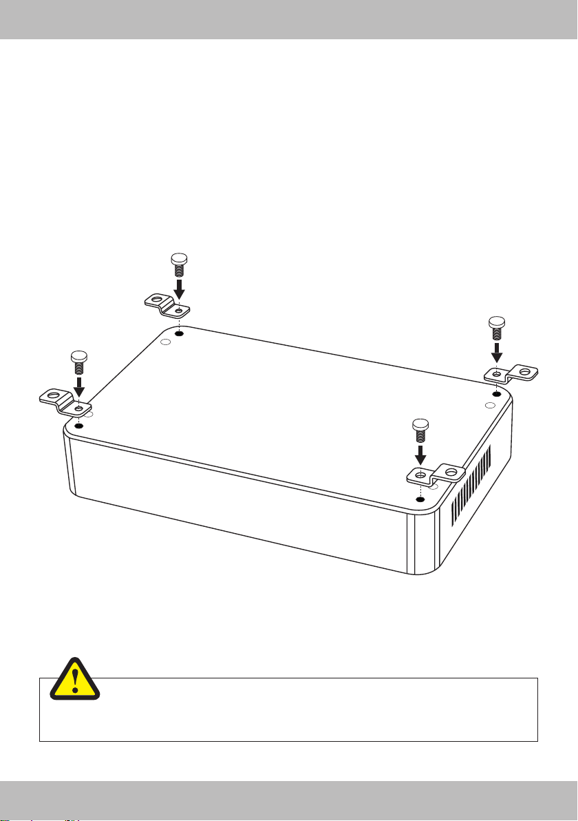
MECHANICAL INSTALLATION
• Avoid any damages on the components of the vehicle like air bags, cables, board computer, seat belts, gas
tank or the like.
• Ensure that the chosen location provides a sufcient air circulation for the amplier. Do not mount the device
into small or sealed spaces without air circulation near by heat dispersing parts or electrical parts of the
vehicle.
• Do not mount the amplier on top of a subwoofer box or any other vibrating parts, whereby parts could
loosen inside.
• The wires and cables of power supply and the audio signal must be as short as possible to avoid any losses
and interferences.
WARNING
Before you start with the installation, disconnect necessarily the GROUND connection wire
from the battery to avoid any risk of electric shocks and short circuits.
6
ENGLISH
ELECTRICAL INTERCONNECTION
BEFORE CONNECTING
For the professional installation of a sound system, car audio retail stores offers appropriate wiring kits. Ensure
a sufcient prole section (at least Ø 5 mm), a suitable fuse rating and the conductivity of the cables when you
purchase your wiring kit. Clean and remove rust-streaked and oxidized areas on the contact points of the battery and the ground connection. Make sure that all screws are xed tight after the installation, because loose
connections cause malfunctions, insufcient power supply or interferences.
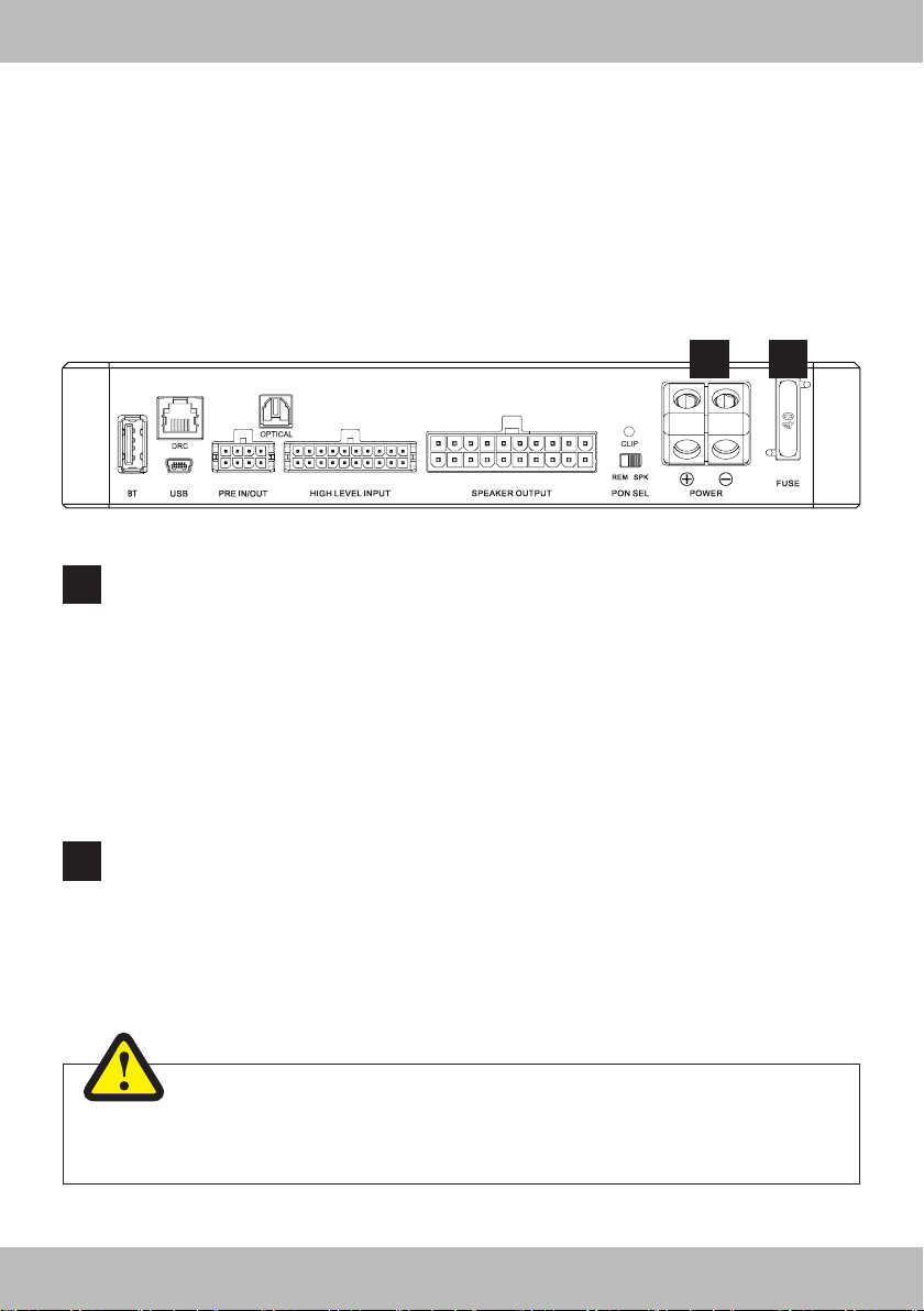
1
POWER
1
Connect the POWER + terminal (+12V) with the +12V pole of the vehicle’s battery. Use a suitable
cable with a sufcient cross section (at least Ø 5 mm) and install an additional in-line fuse. For safety
reasons the distance between the fuse block and the battery should be shorter than 30 cm. Do not set
in the fuse into the fuse block until the installation is accomplished.
Connect the POWER – terminal (ground) with a suitable contact ground point on the vehicle’s chassis. The ground wire must be as short as possible and must be connected to a blank metallic point at
the vehicle’s chassis. Ensure that this ground point has a stable and safe electric connection to the
negative “–”pole of the battery. Check this ground wire from the battery to the ground point if possible
and enforce it, if required. Use a ground wire with a sufcient cross section (at least Ø 5 mm) and the
same size like the positive + power supply wire. This helps reduce most of the interference than can
occur in audio reproduction.
FUSE
2
The inserted fuse (40 A blade) protects the amplier from shorts and capacity overload. If you need to
replace the fuse, make sure to use the same type of fuse with the same rating.
2
WARNING
Make sure the connection polarity is as indicated on the terminals. A misconnection may
result in damage to the amplier. After applying power, wait about 8 seconds before turning
the amplier on.
7
ENGLISH
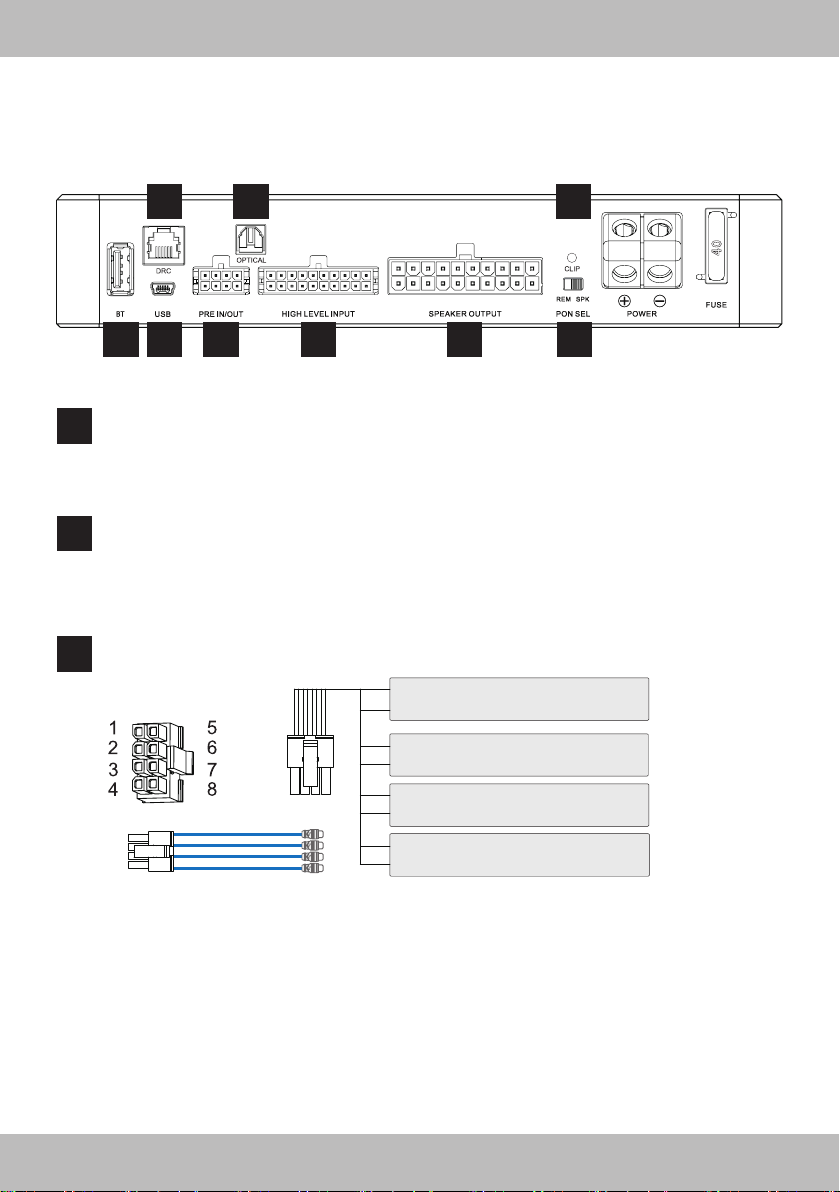
DESCRIPTION OF OPERATION
9 10 11
3 4
BT
3
This USB input is suited for an external Bluetooth™ dongle with wireless audio streaming function
with/or adjusting the DSP by an APP through a smart phone/mobile device.
Check the website “www.musway.de” for more information or ask your car audio retailer.
USB
4
This USB input is suited for the connection with a PC/laptop computer to manage the functions of
the MUSWAY DSP software to set-up the DSP functions of the amplier. The connection is USB
1.1/2.0/3.0 compatible. For downloading the software please visit “www.musway.de/dsp”.
PRE IN/OUT
5
Front view
PRE IN:
Auxiliary low-level stereo signal input to connect an external stereo pre-amplier source.
5 6 7 8
1: Pre-amplied Output – (CH10)
5: Pre-amplied Output + (CH10)
2: Pre-amplied Output – (CH9)
6: Pre-amplied Output + (CH9)
3: Line Level Input – (CH10)
7: Line Level Input + (CH10)
4: Line Level Input – (CH9)
8: Line Level Input + (CH9)
PRE OUT:
2CH pre-amplied output (CH9 & CH10), optimized to drive an amplier for additional external speakers, such as subwoofer or center speakers etc.
8
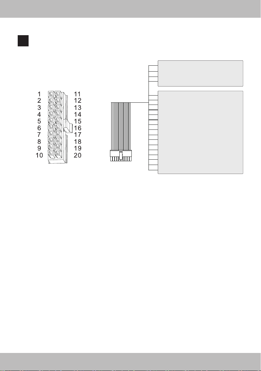
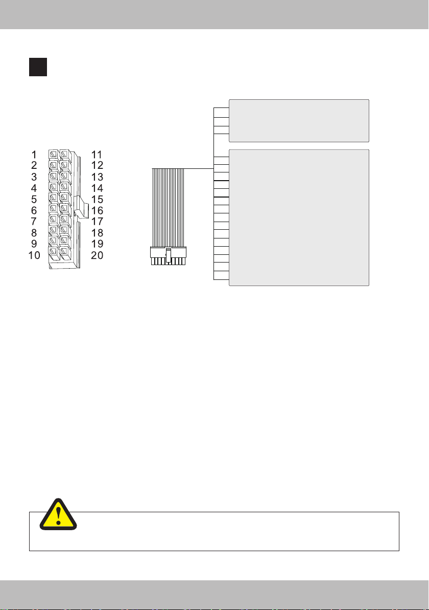
HIGH LEVEL INPUT
6
20 pole multipolar connector to manage the input high-level signals, REM IN connections, etc.
1: Not in use
11: REV LIGHT IN
2: REM OUT
Front view
REV LIGHT IN:
If you connect the reverse gear light cable here, the audio streaming in Bluetooth™ Mode will be
interrupted and the regular audio from the head unit is audible to perceive signal tones from the park
distance control.
12: REM IN
3: HIGH LEVEL INPUT CH 8 –
13: HIGH LEVEL INPUT CH 8 +
4: HIGH LEVEL INPUT CH 7 –
14: HIGH LEVEL INPUT CH 7 +
5: HIGH LEVEL INPUT CH 6 –
15: HIGH LEVEL INPUT CH 6 +
6: HIGH LEVEL INPUT CH 5 –
16: HIGH LEVEL INPUT CH 5 +
7: HIGH LEVEL INPUT CH 4 –
17: HIGH LEVEL INPUT CH 4 +
8: HIGH LEVEL INPUT CH 3 –
18: HIGH LEVEL INPUT CH 3 +
9: HIGH LEVEL INPUT CH 2 –
19: HIGH LEVEL INPUT CH 2 +
10: HIGH LEVEL INPUT CH 1 –
20: HIGH LEVEL INPUT CH 1 +
ENGLISH
REM OUT:
The REM OUT is suited to turn on other devices/ampliers of the sound system, such as additional
ampliers. It takes about 10 seconds to supply the signal to the REM OUT output. The 200 mA output
current capability can also drive an auto-motive relay.
REM IN:
The REM IN is suited to turn on the amplier if a turn-on signal from the head unit/car stereo is available. The voltage must be between 7.5 and 15 VDC.
HIGH LEVEL INPUTS CH1 - 8:
Connect here the amplied speaker outputs coming from the head unit.
CH1 features the Auto Turn-On function through the connection with the speaker outputs of the head
unit.
9
ENGLISH
SPEAKER OUTPUTS
7
20 pole multipolar connector to manage the amplied speaker output signals and power supply.
1: BAT –
11: BAT +
2: BAT –
Front view
BATTERY TERMINALS +/-:
BAT+: Connection terminal for positive (+) power supply from the car specic cable harness
BAT-: Connection terminal for negative (-) power supply from the car specic cable harness
These power terminals are paralleled with the POWER terminals internally. The power cables must be properly
insulated to prevent electrical short. If the POWER terminals are connected with the battery, it is not mandatory
to connect the power supply here.
12: BAT +
3: SPEAKER OUTPUT CH 8 –
13: SPEAKER OUTPUT CH 8 +
4: SPEAKER OUTPUT CH 7 –
14: SPEAKER OUTPUT CH 7 +
5: SPEAKER OUTPUT CH 6 –
15: SPEAKER OUTPUT CH 6 +
6: SPEAKER OUTPUT CH 5 –
16: SPEAKER OUTPUT CH 5 +
7: SPEAKER OUTPUT CH 4 –
17: SPEAKER OUTPUT CH 4 +
8: SPEAKER OUTPUT CH 3 –
18: SPEAKER OUTPUT CH 3 +
9: SPEAKER OUTPUT CH 2 –
19: SPEAKER OUTPUT CH 2 +
10: SPEAKER OUTPUT CH 1 –
20: SPEAKER OUTPUT CH 1 +
SPEAKER OUTPUTS CH1-8:
Connect here speakers (2 - 4 Ohms) according to your sound system. A maximum of 8 speakers can be congured based on the system you wish to create in your vehicle.
If you want to bridge the speaker outputs (BTL mode)and drive the connected speakers/subwoofers with a 4
Ohm load, bridge the channels as follows:
Channel pair 1: SPEAKER OUT1+ (+) & SPEAKER OUT2- (-) with 4 Ohms
Channel pair 2: SPEAKER OUT3+ (+) & SPEAKER OUT4- (-) with 4 Ohms
Channel pair 3: SPEAKER OUT5+ (+) & SPEAKER OUT6- (-) with 4 Ohms
Channel pair 4: SPEAKER OUT7+ (+) & SPEAKER OUT8- (-) with 4 Ohms
WARNING
Do not parallel the outputs, otherwise it may lead the amplier to damage.
10

PON SEL (POWER ON SELECTION)
8
The amplier can be turned on/off by using the following methods:
SPK: Slide the switch into position SPK, if you want to turn on/off the amplier through
the CH1 input channel of the high level speaker inputs and its Auto Turn-On function.
Refer to page 9 and section 6 for more details.
REM: Slide the switch into position REM, if you want to turn on/off the amplier through
the REM and a turn-on signal from head unit/car stereo.
Refer to page 9 and section 6 for more details.
DRC
9
This input is suited for an external MUSWAY digital remote controller. Check the website “www.musway.de” for more information or ask your car audio retailer.
OPTICAL
10
The amplier accepts through its Optical input PCM stereo signals up to 96 kHz / 24 bit sampling frequency rate. Multi-channel signals coming from audio/video sources (such as the audio tracks of a lm
in DVD) can not be reproduced. Connect a ber optic cable with a TOSLINK connector.
CLIPPING LED
11
This LED lights up red if one of the 8 high level inputs (CH1-8) is overdriven. The LED has no function
when an input signal is applied to the Optical input and the Bluetooth™ input. If this LED lights up
reduce the input sensitivity by using the regarding controller Input Sensitivity until the LED goes out.
ENGLISH
SYSTEM CONFIGURATION
In order to congure the inputs, amplied speaker outputs and pre-amplied power outputs, EQ and time
delays for the amplier, it must be interfaced with the PC. When you get to this point you must already be
aware of what type of system you intend to set up. In order to avoid complications in preparation, make sure
the following points before you start:
• The type of signals that will be assigned to the inputs (e.g.: front left or center or subwoofer, etc.).
• The speakers in the system (e.g.: 3-way front or sub stereo or 2-way rear, etc.).
• If there are passive crossovers that manage groups of speakers (e.g.: 3-way systems with active
midrange).
• If you intend to use an external mono amplier to drive a subwoofer.
• If you intend to use the amplied outputs of the amplier bridged (BLT mode), thus increasing the power on
the output.
WARNING
Before turning on the system, set the head-unit output level to a lower level (approximately
20% of its maximum excursion) to avoid damaging the speakers during calibration.
11
 Loading...