

MUSTOOL MT8206 User Manual

User’s Manual For MT8206
◆ Multimeter with 200K A/D sampling and 4000 counts auto-range
◆ One-button switch to graphical waveform display during measurement
◆ Reliable panel calibration technology , memory calibration coefficients
◆ Displaying historical data and real-time measurement on the same screen
◆ Featuring DC/AC voltage/current, resistance, capacitance/mF
Frequency/duty cycle, diode/continuity tes

Introduction
Dear users,
Thank you for purchasing the MT8206 Digital Graphical Multimeter. The digital graphical multimeter capable
of displaying the waveform is inevitable in the development of the measuring instrument from analog (pointer). I
believe that the innovative function combination and user-friendly design of MT8206 Digital Graphical Multimeter
will be of great help to your on-site inspection. Please read the this manual carefully before use, especially the
“Safety Instruction”. Keep this manual properly after reading it for future reference.
Intellectual property
This product features a number of proprietary technologies, and the purchase or use of this device does not
represent the transfer of these intellectual property rights. It is an infringement of intellectual property rights to copy
and apply all or part of the technology without the consent of our company. The intellectual property rights include,
but are not limited to, patents, trademarks, publications and website.
·The information provided in this manual supersedes all previous information published, and is subject to change
only on the official website of the company.
·The patents of this products awarded and applied are protected by the Patent Law of the People's Republic of
China.
·Our company reserves the right to change product specifications, prices and software upgrades.
·Our company has the final interpretation of product manuals and marketing activities.

Directory
SAFETY INSTRUCTIONS..............................................................................................................................................1
INSTRUMENT INTRODUCTION................................................................................................................................. 4
Features..................................................................................................................................................................... 4
Buttons...................................................................................................................................................................... 6
Insert plug..................................................................................................................................................................7
BASIC OPERATION....................................................................................................................................................... 8
Power on/off..............................................................................................................................................................8
Automatic shut-down................................................................................................................................................8
Battery replacement.................................................................................................................................................. 8
OPERATION OF MULTIMETER.................................................................................................................................. 9
Enabling the multimeter mode..................................................................................................................................9
Switching measurement functions............................................................................................................................9
Relative value measurement (REL) mode..............................................................................................................10
Application of relative value measurement (REL) mode.......................................................................................10
Holding and saving measurement data...................................................................................................................12
Reading and deleting measurement data................................................................................................................ 13

AC and DC voltage measuremen............................................................................................................................15
AC and DC current (mA,10A) measuremen.......................................................................................................... 17
Frequency/duty cycle measurement........................................................................................................................19
Resistance measurement......................................................................................................................................... 20
Diode/continuity test...............................................................................................................................................21
Capacitance measurement.......................................................................................................................................23
mF (large capacitance) measurement..................................................................................................................... 24
WAVEFORM DISPLAY OPERATION....................................................................................................................... 25
Enabling waveform display mode.......................................................................................................................... 25
Buttons and main menu.......................................................................................................................................... 25
Automatic measurement of waveform....................................................................................................................28
Holding and saving signal waveform..................................................................................................................... 28
Saving and reading signal waveform......................................................................................................................29
Deleting signal waveform saved.............................................................................................................................29
TECHNICAL PARAMETERS AND PACKING LIST................................................................................................ 30
Features and technical parameters..........................................................................................................................31
Description of symbols and icons...........................................................................................................................33
Packing lis............................................................................................................................................................... 33
1
Safety instructions
The MT8206 digital graphical multimeter is designed in accordance with the requirements for the over-voltage
category of CAT II-1000V and CAT III-600V and level 1 pollution protection in IEC1010-1 safety specification.
1. Check the case before use. Do not use the device with damaged case; check for cracks or missing plastic parts.
Check the insulation of the probe and connecting wires. Do not touch the metal part of the probe when using it;
2. Do not operate it in high temperature, humidity, rain and flammable and explosive environment or when the
instrument is wet;
3. Never measure the voltage/current beyond its maximum limits;
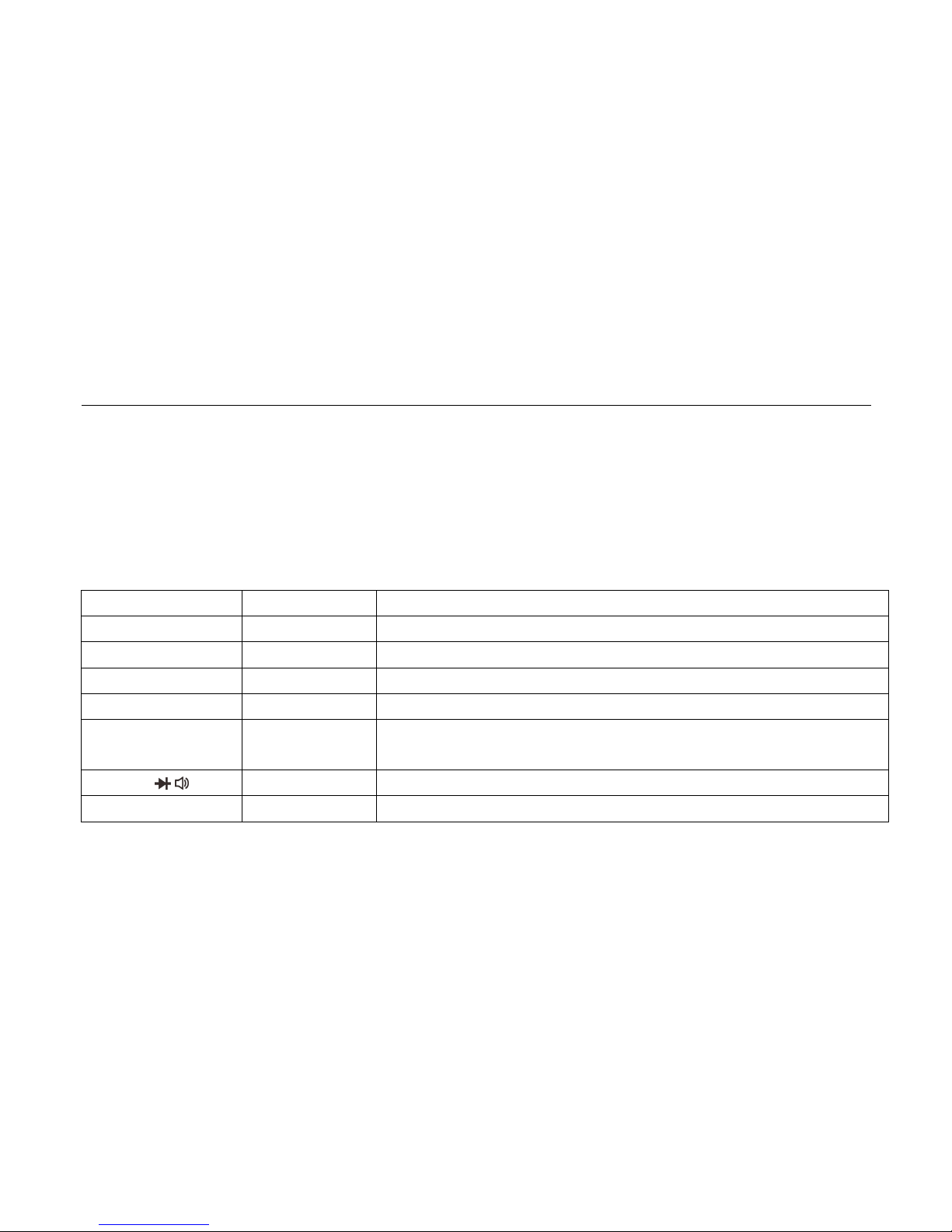
Measuring function
Input
Maximum limit
V DC
V/Ω,COM
1000V DC/AC peak, within 10 seconds
V AC
V/Ω,COM
750V DC/AC RMS, within 10 seconds
Hz
V/Ω,COM
380V DC/AC RMS, within 10 seconds
mA AC/ DC
400mA,COM
400mA DC/AC RMS, 250V/500mA fuse
A AC/ DC
10A,COM
10A DC/AC RMS, within 30 seconds, 15 minutes cooling interval,
250V/10A fuse
Ω / /
V/Ω,COM
250V DC/AC RMS, within 10 seconds
Capacitance/mF
V/Ω,COM
250V DC/AC RMS, within 10 seconds

2
4. When changing the measurement function, before inserting the probe plug and turning on and off the
multimeter, be sure to remove the probe from the test point;
5. Pay attention to the safety Warning signal displayed by the meter. When the measured voltage exceeds
DC1000V or AC750V, the buzzer will give long alarm; when the voltage range of DC1000V and AC750V
exceeds the safe voltage (24V), the buzzer will sound three times and the high voltage sign will be displayed
to alert the operator for safety;
6. When the voltage to the ground on the reference input “COM” of the meter is 500V, do not measure voltage
measurement;
7. Although the probe 10A range is connected with a 250V fuse, it is very dangerous to measure the voltage
incorrectly, which may damage the instrument;
8. When the current, resistance, continuity test, diode, capacitor and other positions are selected, never connect the
probe to both terminals of the voltage source;
9. Before performing resistance and diode/continuity tests, turn off the power to the device under test and
discharge the capacitor in the circuit.
10. Before opening the back cover to replace the fuse, turn off the power supply and disconnect the probe from the
circuit under test; replace the fuse with the same specifications;
11. Do not modify, disassemble or use the products and accessories for any purpose other than the design purpose
of the product. Do not replace parts and accessories at will;
12. Do not charge the battery. Replace the battery in time when the low voltage symbol is displayed on the
screen.
3
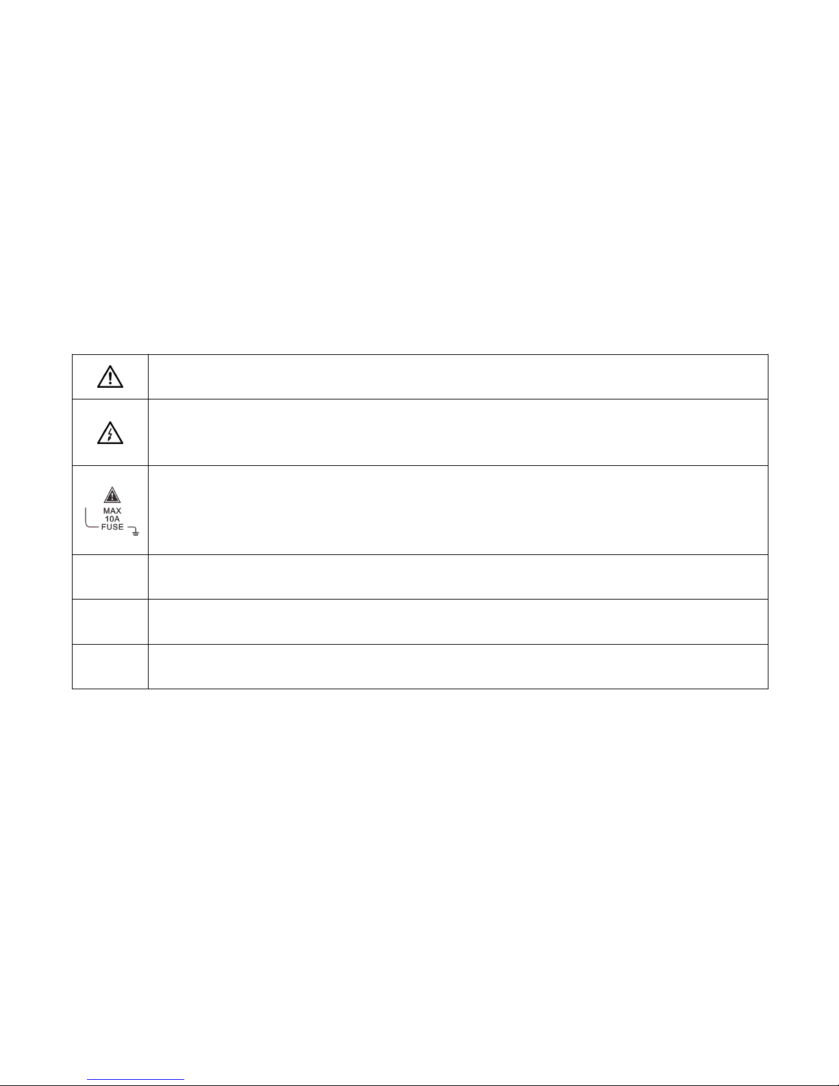
Safety signs
Caution! Danger! When this sign is found near other symbols or jack terminals, the users are
prompted to follow the instructions in this manual to prevent instrument damage/personal injury.
Caution! Electric shock! The presence of this sign near one or more terminals indicates that these
terminals may carry dangerous voltages during use. For the sake of safety, do not touch the test
probes of the probes when the terminals are energized.
This sign found near the terminal block indicates that the maximum withstand current between the
terminal and COM is 10A.
FUSE indicates a built-in 10A (or 500mA) fuse; current measurement is not allowed on circuits with
voltage of AC 250V or higher.
Prompt!
The prompt states that special care should be taken during operation. Incorrect operation can result in
erroneous measurement results or damage to parts.
Attention!
The attention states that care must be taken during operation in case of damage to this product and
other property.
Warning!
The Warning states that the operators should concentrate on the operation. Errors or violations may
result in personal injury or even life risk.
4
Instrument introduction
Features
◆ Digital multimeter with 200k high-speed A/D sampling,
4000 counts auto-range, one-button switch of graphical
waveform display during measurement
◆ High reliability with panel calibration technology and memory
calibration, sparing the need for adjustment with potentiometer
◆ Storing 100 sets of data and 10 waveforms independently
◆ Capable of holding waveform and data during measurement,
easy to view and analyze
◆ Realizing one-button automatic waveform capture,
operator-friendly to learn and operate

5
◆ Displaying historical data and real-time measurement on the
same screen with unique record reading mode for easy comparison
◆ Effectively eliminating lead resistance, distributed capacitance or interference signals with relative value
measurement (clearing)
◆ Extending battery life with automatic shutdown function
◆ Featuring DC/AC voltage/current, resistance, capacitance/mF (large capacitance)
Frequency/duty cycle, diode/continuity test
◆ Frequency measurement with 5Hz ~ 5MHz automatic switching range and the maximum input of 380VAC
◆ 10A AC and DC current measurement with protection against voltage error
◆ AC voltage bandwidth up to 20kHz
6
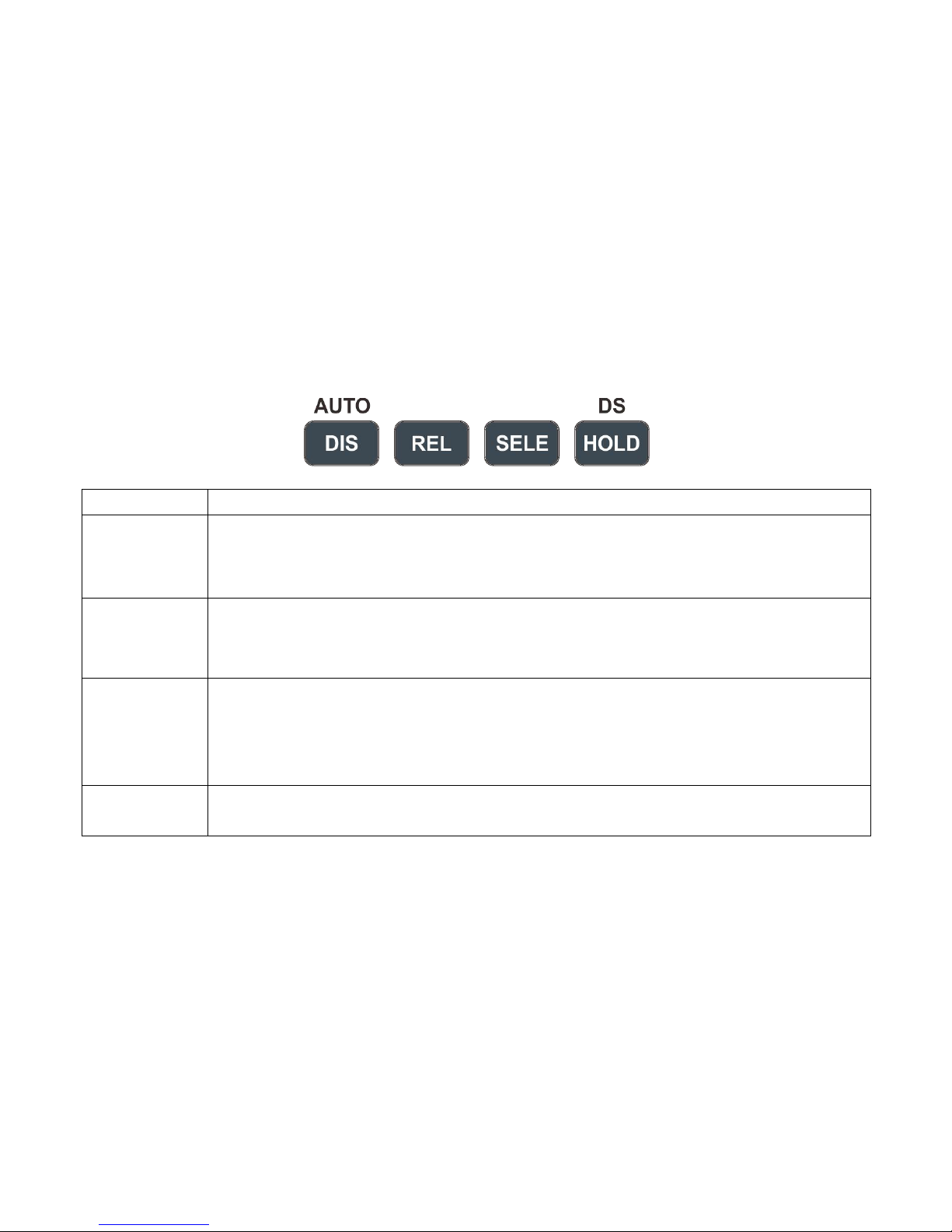
Buttons
NAME
FUNCTIONS
DIS/AUTO
1. Manually/automatically switching range during DMM measurement;
2. Switching between multimeter/graphical waveform display mode (Hold down);
3.Automatic capture during waveform measurement
REL
1. Showing relative value measurement during DMM measurement;
2. Paging up when reading stored data/waveform;
3. Scaling down the waveform and displaying period during waveform measurement
SELE
1. Selecting DC/AC mode;
2. Measuring frequency/duty cycle;
3. Paging down when reading stored data/waveform;
4. Scaling up waveform and displaying period during waveform measurement
HOLD/DS
1. Saving data/waveform;
2. Reading stored data/waveform (Hold down)
7
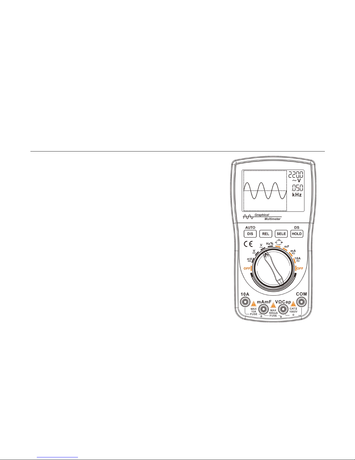
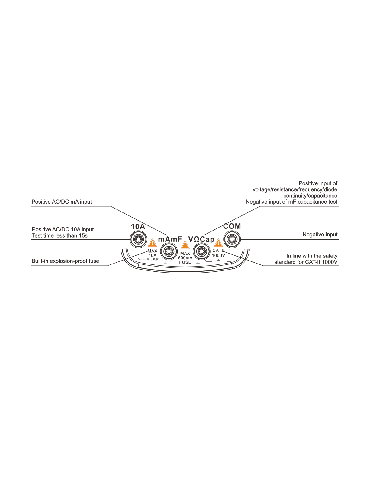
Insert plug
8
Basic Operation
Power on/off
Turn the knob to the desired measurement position to turn the multimeter on. Turn the knob to the "OFF"
position again to turn off the power.
Attention!
• Move the test probe away from the test point before turning the knob (shutdown).
• When the meter is used, turn off the power in time.
Automatic shut-down
If there is no button operation within the set 15 minutes, the meter will automatically shut down.
Tips
• Only the display of the main chip and LCD screen is turned off when the instrument is
automatically shut down, but there is still a certain leakage current.
• If it is not used for a long time, switch the knob to “OFF” position
Battery replacement
When the meter is in use and the low-voltage symbol appears in the upper right corner of the LCD screen,
the user should replace the battery as soon as possible.
When the meter is not used for a long time, take out the battery to prevent the battery from leaking and
damaging the meter.
Warning!
Pay attention to the safety of the battery.
 Loading...