

INSTALLATION INSTRUCTIONS
INSTRUCCIONES PARA LA INSTALACIÓN n INSTRUCTIONS D’INSTALLATION
E.L. Mustee & Sons, Inc.
Brook Park, OH 44142
Email: info@mustee.com
Web: www.mustee.com
Models:
Modelos:
Modèles:
ASSEMBLY / INSTALLATION / REPAIR PARTS
30 (30") 68 (32")
30 68
With Standard Base
DURASTALL®
Cabina de Ducha
Shower Stall
n
n
Con plato de ducha estándard n Avec base standard
Cabine de Douche
PARA ENSAMBLAR / INSTALACIÓN / PIEZAS DE REPARACIÓN
POUR SE RÉUNIR / INSTALLATION / PIÈCES DE RÉPARATION
INSTALLATION VIDEO AVAILABLE @mustee.com
Video de instaladón disponible @mustee.com
La vidéo d'Installation disponible @mustee.com
READ ALL INSTRUCTIONS CAREFULLY AND INSPECT PRODUCT FOR DAMAGE BEFORE STARTING YOUR INSTALLATION.
LEA TODAS LAS INSTRUCCIONES DETENIDAMENTE Y VERIFIQUE QUE EL PRODUCTO NO ESTÉ DAÑADO ANTES DE COMENZAR LA INSTALACIÓN.
VEUILLEZ LIRE ATTENTIVEMENT TOUTES LES INSTRUCTIONS ET VÉRIFIER QUE LE PRODUIT N’EST PAS ABÎMÉ AVANT DE PROCÉDER À L’INSTALLATION.
INCLUDED IN CARTON: EN EL PAQUETE SE INCLUYE: CONTENU :
One (1) shower cabinet Una (1) cabina para ducha Une (1) module de douche
One (1) shower floor Un (1) piso de la ducha Un (1) bac à douche
One (1) shower valve Una (1) válvula para ducha Une (1) valve de douche
One (1) drain assembly Un (1) dispositivo de drenaje Un (1) tuyau d'évacuation
One (1) safety hand rail Un (1) con baranda de seguridad Un (1) barre d’appui
TOOLS AND MATERIALS REQUIRED FOR INSTALLATION:
HERRAMIENTAS Y MATERIALES PARA LA INSTALACIÓN DEL PRODUCTO: n OUTILS ET MATÉRIEL NÉCESSAIRES À L’INSTALLATION :
Screwdrivers (standard & Phillips) Destornilladores (estándar y Phillips) Tournevis (standard et cruciforme)
Drill Taladro Perceuse
Hole saws (1" and 1
Adjustable wrench Llave ajustable Clé à molette
Open-end wrench set Juego de llaves de boca Jeu de clés plates
Level Nivel Niveau
Tape measure Cinta métrica Mètre ruban
Pliers Alicates Pinces
Hacksaw or sabre saw – fine tooth Segueta o sierra eléctrica de dientes finos Scie à métaux ou scie sauteuse à dents fines
Caulking (waterproof)
Pipe cement/primer (PVC) Cemento para tuberías /imprimador (PVC) Colle pour tuyau de PVC
1
/4") Sierras de perforación (1" y 1 1/4") Scie-cloche (1 po et 1 1/4 po)
Masilla (prueba del agua) Mastic (preuve de l’eau)
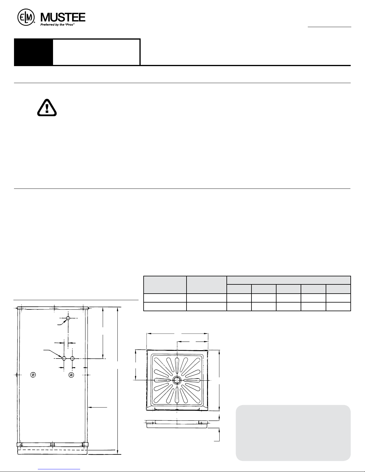
ROUGH-IN
ENCUADRE PRELIMINAR n SCHÉMA DE MONTAGE
DIA. HOLE
1"
11/4" DIA.
(2 HOLES)
*3
SEE NOTE
*1
2 "
4"
*2
1
/4"
6
29
*4
FRONT
1
/2"
A
E
*5
MODEL
NOM. SIZE
Tamaño Nominal
Dimensions Nom.
30"
32"
HEIGHT
30
68
MODEL NO.
Número de Modelo
N° d e
Modèle
30
68
B
D
.
ALTURA .HAUTEUR
1
/2"
2
1
/2"
2
DIMENSION
A B C D
73" 30 1/8" 30 1/8" 15 1/16" 15 1/16"
1
/4" 32 5/8" 32 5/8" 16 5/16" 16 5/16"
74
NOTE: It is recommended to locate the shower valve
in a side wall not more than 16" back from front of
the cabinet.
NOTA: Se recomienda colocar la válvula de la ducha en
una pared lateral a no más de 16" (40 cm) detrás del frente de
la cabina.
C
Remarque : il est recommandé d’installer le robinet de
douche sur un panneau latéral à un maximum de 16 po
(40 cm) de l’avant de la cabine.
Español
*1 Orificio de 1" pulg
de diámetro
*2 Vea la nota
*3 (Dos orificios) 1
pulg de diámetro
*4 Frente
*5 Modelos 30, 68
n
Dimensión n Dimension
Français
*1 Trou de 1 po
*2 Voir la note
*3 2 trous de 1
1
/4"
*4 Avant
*5 Modèles 30, 68
1
/4 po
E
INSTALLATION INSTALACIÓN INSTALLATION
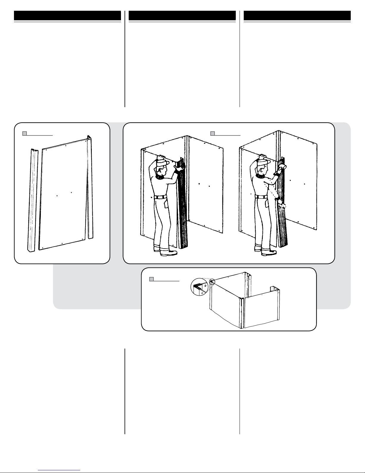
1. Hold the center panel upright with your left hand.
Let the bottom rest on the floor. With the right hand,
angle the corner lock strip and engage it to the left
side of the center panel at the top. (Make sure the
smooth side of the panel is to the inside.) Align the
top of the lock strip to the top of center panel. Use
the palm of your hand, push or tap the lock strip
onto the panel, down about 10 inches from the top.
Then take a hammer and strike the lock strip starting
at the top. As the lock strip is seated, it will continue
to engage the panel (make your strike 3 to 4 inches
above where the panel is starting to join). Repeat the
process to put the lock strip on the other side of the
center panel with the lock strip. (Fig. 1)
Fig. 1
1. Sostenga el panel central en posición vertical con la
mano izquierda. Deje que la parte inferior se apoye sobre
el piso. Con la mano derecha, coloque el perfil en el
ángulo y trábelo al lado izquierdo del panel central en la
parte superior. (Asegúrese de que la parte lisa del panel
esté hacia adentro). Alinee la parte superior del perfil a
la parte superior del panel central. Con la palma de la
mano, empuje o golpee suavemente el perfil hacia el
panel, aproxidamente 10" (25 cm) desde el borde superior.
Después golpee el perfil con un martillo desde la parte
superior. Mientras que el perfil esté apoyado, continuará
sosteniendo el panel (asegúrese de golpear de 3" a 4" (7
a 10 cm) arriba de donde el panel comienza a juntarse).
Repita el proceso para poner el otro perfil al otro lado del
panel. (Fig. 1)
Fig. 2a
1. Tenez le panneau central à la verticale avec votre main
gauche, en laissant le bas reposer par terre. Avec la main
droite, pliez le joint d’étanchéité de coin et insérez-le
dans la partie supérieure du panneau central, du côté
gauche (assurez-vous que le côté lisse du panneau est à
l’intérieur). Alignez le haut du joint sur le haut du panneau
central. Avec la paume de la main, appuyez ou tapez sur
le joint pour l’insérer dans le panneau d’environ 10 po
(25 cm). À l’aide d’un marteau, tapez le joint sur toute sa
longueur, en commençant par le haut, en tapant 3 à 4 po
(7 à 10 cm) au-dessus de l’endroit où le joint pénètre dans
le panneau). Procédez de la même façon pour installer
le joint d’étanchéité sur l’autre côté du panneau central.
(Fig. 1)
2. Working from the outside, angle the Center
Panel Assembly slightly, to start engagement to
the side panel. Repeat the procedure used to put
the lock strip on the center panel. Secure the strip
in place by tapping from top to bottom. Repeat
procedure for other side and putting on the front
supports. (Fig. 2a & 2b)
3. Insert a 1/4" – 20 Flat Head Machine Screw
through the hole in molded Safety Rail Washer.
Note that there are two holes punched in the
center of each panel. Screw the washer/screw
assembly into each hole from outside as shown.
Do not overtighten! (Fig. 3)
Fig. 2b
2. Si trabaja desde afuera, acomode el panel central
ligeramente en ángulo, para comenzar a montar el panel
lateral. Repita el procedimiento con el que puso el perfil en
el panel central. Asegúrese de que el perfil quede firme en
su lugar golpeando suavemente de arriba a bajo. Vuelva a
realizar el procedimiento para colocar el panel del otro lado
y montar los soportes frontales. (Fig. 2a y 2b)
3. Inserte un tornillo de cabeza plana para máquina
1
/4" – 20 en la arandela para la baranda de seguridad.
Observe que hay dos orificios perforados en el centro
de cada panel. Atornille el conjunto de arandela/tornillo
en cada uno de los orificios desde afuera, como se
muestra. ¡No apriete demasiado! (Fig. 3)
2. En vous tenant à l’extérieur, orientez doucement le
panneau central de façon à ce qu’il s’enclenche dans
le panneau latéral. Installez le joint d’étanchéité, puis
tapez-le de haut en bas. Répétez la manipulation pour
l’autre côté et positionnez l’ensemble sur les supports
avant. (Fig. 2a et 2b)
3. Insérez une vis à tête plate n° 20 de
le trou de la rondelle de la rampe d’appui moulée.
Repérez les 2 trous au centre de chaque panneau.
Serrez une vis avec une rondelle dans chaque trou à
partir de l’extérieur, comme dans la figure. Ne serrez
pas trop ! (Fig. 3)
1
/4 po dans
2

4. Position Safety Rail inside cabinet so that
*1
*2
Safety Rail
Ribs
#10 x
5
/8"
Screw
1
/4" – 20 Flanged Nut
*1
*2
*3
*4
each end is located between the two ribs on the
inside of the front support extrusions. Use a #10
5
/8" Truss Head Screw to secure both ends of
x
the Safety Rail through the pre-punched holes
in the front supports. Position side and rear
mounting pods of Safety Rail onto previously
installed mounted screws. Place a
Flanged Nut on each mounting screw and
tighten securely using a
7
/16" wrench. (Fig. 4)
1
/4" – 20
4. Coloque la baranda de seguridad dentro de la cabina
de manera tal que cada extremo quede en medio de las
dos costillas de la parte interna de los moldeamientos de
apoyo frontales. Introduzca los tornillos de cruz #10 x
en los orificios marcados en los soportes del frente para
asegurar los dos extremos de la baranda de seguridad.
Coloque los sostenes traseros y laterales de montaje
que tiene la baranda sobre los tornillos de sujeción
previamente dispuestos. Coloque una tuerca con brida
1
de
/4" – 20 en cada uno de los tornilllos de sujeción y
ajústelos usando la llave de
7
/16". (Fig. 4)
4. Placez la barre dans la cabine de façon que chaque
extrémité s’insère entre les 2 nervures situées à
l’intérieur des extrusions de support avant. Serrez une
5
vis à tête bombée n° 10 de
/8"
supports avant de chaque extrémité de la barre. Placez
les supports de montage latéraux et arrière de la barre
d’appui sur les vis préinstallées. Vissez un écrou à
embase n° 20 de
une clé de
1
7
/16 po. (Fig. 4)
5
/8 po dans le trou des
/4 po sur chaque vis et serrez avec
BEFORE PROCEEDING TO STEP 5, POSITION BASE IN PERMANENT LOCATION – SEE BASE INSTRUCTIONS
ANTES DE IR AL PASO Nº 5, COLOQUE EL PLATO DE LA DUCHA EN EL LUGAR DONDE VA A QUEDAR DE MANERA PERMANENTE. VER INSTRUCCIONES DEL PLATO.
AVANT DE PASSER À L’ÉTAPE 5, POSITIONNEZ LA BASE À L’ENDROIT CHOISI POUR L’INSTALLATION DE LA CABINE DE DOUCHE (REPORTEZ-VOUS AUX INSTRUCTIONS DE LA BASE).
Fig. 3
*1 1/4" – 20 x 1"
flat-head screw
*2 Safety-rail washer
Cuadro 3
*1 Tornillo de cabeza plana
1
/4" – 20 x 1"
*2 Arandela para la baranda
de seguridad
Le schéma 3
*1 Vis à tête plate 1/4 po –
20 x 1 po
*2 Rondelle de rampe
d’appui
BEFORE INSTALLING WALL PANELS, YOU MUST ASSEMBLE THE DRAIN
AND SET THE SHOWER FLOOR AS DESCRIBED ON PAGE 5.
ANTES DE INSTALAR LOS PANELES DE PARED, USTED DEBE ENSAMBLAR EL DREN Y FIJAR LA BASE SEGÚN LO DESCRITO EN LA PÁGINA 5.
AVANT D’INSTALLER DES PANNEAUX DE MUR, VOUS DEVEZ ASSEMBLER LE DRAIN ET PLACER LA BASE COMME DÉCRIT À LA PAGE 5.
5. Apply a small bead of quality waterproof caulking
(not furnished) in track on Shower Base (Fig. 5). Use
the Safety Rail to lift the walls and place into the
track against the caulking. It may be necessary to
re-tap the Corner Lock Strips and push bottom of
panel into the groove to ease installation.
Fig. 4
5. Aplique una pequeña porción de masilla a prueba de
agua (no incluida) sobre el borde de la base de la ducha
(Fig. 5). Use la baranda de seguridad para levantar las
paredes y colóquela en la marca sobre la masilla. Puede
ser necesario volver a golpear suavemente el perfil y
empujar la parte inferior del panel en la ranura para que la
instalción sea más sencilla.
Cuadro 4
*1 #10 x 5/8" (15.86 mm) Tornillo
*2 Costillas
*3 Verja de la seguridad
*4 Tuerca con brida
1
/4" – 20 x 1"
Le schéma 4
*1 #10 x 5/8 po (15,86 mm) Vis
*2 Nervures
*3 Balustrade de sûreté
*4 Écrou à embase
20 x 1 po
5. Appliquez un petit cordon de calfeutrage au silicone
(non fourni) dans la rainure de la base (Fig. 5). En
utilisant la barre d’appui, soulevez les parois de la
cabine et déposez-les sur le cordon de calfeutrage.
Pour faciliter la mise en place, vous devrez peut-être
retaper le joint d’étanchéité de coin et forcer le bas des
panneaux dans la rainure.
1
/4 po –
6. From the outside, insert a 1/4" – 20 x 1/2" Truss
Head Screw in the Base and through the prepunched hole in the Front Support. Secure with
1
/4" x 20 Hex Nut on the inside. Repeat for the
a
remaining Front Support. Insert a #10 x
Head Tapping Screw into the pre-punched center
hole of the back panel (this will align the panel to
the base.) Follow the same procedure for both side
panels. Tighten all three center screws, then start the
remaining six screws. After all screws are started,
tighten securely. (Fig. 6)
3
/8" Truss
Visit : www.mustee.com
6. Desde el lado de afuera, coloque los tornillos en cruz de
1
/4" – 20 x 1/2" en el plato y a través del orificio marcadoa
en el soporte frontal. Asegúrelo con una tuerca hexagonal
1/4" x 20 desde el lado de adentro. Repita el proceso para
el otro soporte frontal. Inserte un tornillo rosca de cabeza
en cruz #10 x
trasero (esto alineará el panel al plato). Realice el mismo
procedimiento para los dos paneles laterales. Ajuste los
tres tornillos del centro y luego coloque los otros seis.
Después de poner todos los tornillos en su lugar, ajústelos
hasta que queden firmes. (Fig. 6)
3
/8" en el orificio central marcado del panel
6. Depuis l’extérieur de la cabine, insérez une vis à tête
bombée n° 20 de
trous du support avant. Serrez en place de l’intérieur avec
un écrou n° 20 de
l’autre support avant. Insérez une vis autotaraudeuse à tête
bombée n° 10 de
arrière pour aligner le panneau et la base. Procédez de la
même façon pour les 2 panneaux latéraux. Serrez les 3 vis
centrales, puis insérez les 6 vis restantes. Une fois les 6 vis
en place, serrez-les à tour de rôle. (Fig. 6)
1
/4 x 1/2 po dans la base et dans l’un des
1
/4 po. Procédez de la même façon pour
3
/8 po dans le trou central du panneau
3

4
7. Set Top Frame in place and secure to panels
and front supports following the same procedure
previously used for securing the base.
7. Coloque el marco superior en su lugar y asegúrelo
a los paneles y los soportes frontales usando el mismo
procedimiento que usó para asegurar el plato.
7. Mettez le dessus de cabine en place et fixez-le aux
panneaux et aux supports avant en procédant comme
pour la base.
8. Set Threshold in place between the front support
extrusions. Be sure that threshold “notch” is locked
into base “tee” section. Insert a
1
/4" – 20 Hex Head
Screw through the pre-punched hole in the front
support flange and screw into the threaded area of
the Threshold. Follow the same procedure for the
other side. After both screws are started, tighten
securely. (Fig. 7)
8. Coloque el umbral en medio de los moldeamientos
de los soportes frontales. Asegúrese de que la ranura
del umbral trabe con la división “T”. Inserte un tornillo
de cabeza hexagonal
1
/4" – 20 en el orificio marcado
en el reborde del soporte frontal y atorníllelo en el
área roscada del umbral. Repita el procedimiento
para el otro lado. Una vez que los dos tornillos estén
colocados, ajústelos hasta que queden firmes. (Fig. 7)
8. Installez le seuil de porte entre les extrusions du
support avant. Assurez-vous que l’encoche du seuil
est insérée dans la section en T de la base. Insérez
une vis à tête hexagonale n° 20 de
1
/4 po par le
trou du raccord de support avant puis dans le trou
correspondant du seuil de porte. Procédez de la même
façon pour l’autre côté. Une fois les 2 vis en place,
serrez-les à tour de rôle. (Fig. 7)
9. Slide Curtain Hooks onto Curtain Rod. Position
Curtain Rod over molded sockets on top surface
of Top Frame. Press Curtain Rod down to snap in
place. These units are not recommended for use
with a door.
9. Deslice los ganchos para cortina en la varilla para
cortina. Coloque la varilla para cortina sobre los
enchufes moldeados en la superficie superior del
marco superior. Presione la varilla para cortina hacia
abajo hasta que encaje en su lugar. No se recomienda
usar estas unidades con una puerta.
9. Glissez les crochets du rideau sur la pôle à rideau.
Positionnez la tringle à rideau sur les douilles moulées,
sur le dessus de la partie supérieure du cadre.
Appuyez sur la tringle pour l’enclencher en place. Il
n’est pas recommandé d’utiliser ces éléments avec
une porte.
Cuadro 6
*1 #10 x 3/8" (9.52 mm) Tornillo
*2
1
/4" (6.35 mm) – 20 x Tuerca
hexagonal
*3
1
/4" (6.35 mm) – 20 x 1/2" (12.7 mm)
Tornillo de cruz
*4 Frente
Le schéma 6
*1 #10 x 3/8 po (9,52 mm) Vis
*2
1
/4 po (6.35 mm) – 20 x Écrou
hexagonal
*3
1
/4 po (6,35 mm) – 20 x 1/2 po
(12,7 mm) Vis à tête bombée
*4 Avant
Cuadro 7
*1 Muesca
*2 Ducha con umbral
*3 Unión T
*4 Modelo 30:
1
/4" (6.35 mm) –
20 x
1
/2" (12.7 mm) Tornillo de
cabeza hexagonal
Modelo 68: Tornillo de cabeza
hexagonal con arandela del
n.° 14 x
3
/4" (19.05 mm)
Le schéma 7
*1 Entaille
*2 Douche de porte
*3 T
*4 Modèle 30 :
1
/4 po (6,35 mm)
– 20 x
1
/2 po (12,7 mm) Vis à
tête hexagonale
Modèle 68 : Vis à tête hexagonale à
embase
3
/4 po (19,05 mm), nº 14
“Front”
1
/4" – 20 x 1/2"
Truss-Head Screw
1
/4" – 20 x Hex Nut
#10 x 3/8" Screw
*1
*2
*3
*4
Notch
Threshold
Tee
Model 30
1
/4" – 20 x 1/2" Hex-Head Screw
Model 68
#14 x 3/4" Hex Washer Head Screw
*1
*2
*3
*4
8
16
Caulk this area
all around
Base “Front”
*1
*2
Fig. 6
Fig. 7
Fig. 5
Cuadro 5
*1 Coloque masilla entorno
a toda esta área.
*2 Frente de la base
Le schéma 5
*1 Appliquez du calfeutrage
autour de cette section.
*2 Avant de base

5 5
3
4
5
6
4
2
5
6
8
3
7
2" (IRON, ABS, PVC) PIPE, SANITARY DRAIN
OPENING
OPENING
SUB FLOOR
SUB
FLOOR
SHOWER
BASE
3
1
/2"
5"
*A
*A
*B
*C
*B
*D
DRAIN SECTION
SHOWER BASE
SECCIÓN DEL DESAGÜE DEL
PLATO DE LA DUCHA
DRAIN DE LA BASE
SECTIONAL VIEW – STANDARD BASE AND DRAIN
VISTA POR SECCIONES – PLATO DE DUCHA Y DESAGÜE ESTÁNDARD n VUE DE COUPE – BASE STANDARD ET DRAIN
*A Base del suelo
*B Abertura
PLATO DE LA DUCHA ESTÁNDARD
*C Desagüe sanitario de PVC, ABS o hierro de 2" (5,1 cm)
*D Base de la ducha
BASE STANDARD
*A Sous-plancher
*B Ouverture
*C 2 po (5,1 cm) – Siphon sanitaire métallique, ABS ou PVC
*D Base de douche
DRAIN ASSEMBLY / BASE INSTALLATION
MONTAJE DEL DESAGÜE / INSTALACIÓN DEL PLATO DE LA DUCHA n TUYAU D’ÉVACUATION / INSTA LLATION DE BASE
A. Check shower base carefully making sure it
is not damaged.
A. Asegúrese de que el plato de la ducha no esté dañado. A. Examinez la base de cabine soigneusement pour vous
assurer qu’elle n’est pas endommagée.
B. Assemble drain to shower base (see
illustration below) using all washers provided.
Do not use any putty or thread sealant
compound under flange or on threads of either
the drain body or locknut. Hand tighten locknut,
then wrench an additional
3
/4 turn – maximum.
B. Monte el desagüe del plato de ducha (ver
ilustración más abajo) usando todas las arandelas. No
utilice ningún tipo de masilla o sellador debajo de la
brida o las roscas del desagüe o la tuerca de cierre.
Ajuste la tuerca de cierre con la mano y después dele
una vuelta de
3
/4 como máximo, con la llave.
B. Reliez le drain à la base en installant toutes les
rondelles fournies (voir la figure ci-dessous). Ne mettez
pas de mastic ou de ruban pour joint fileté sous la bride
ou sur les filets du drain ou du contre-écrou. Vissez le
contre-écrou à la main, puis utilisez une clé pour le serrer
d’un
autre 3/4 de tour maximum.
D. Place shower base directly on sub-floor or
slab. Make sure it is level!
D. Coloque el plato de la ducha directamente
en la base del suelo o la losa. Asegúrese de que
esté nivelado.
D. Placez la base directement sur le sous-plancher
ou la dalle de béton, et assurez-vous qu’elle est
de niveau.
E. Seal waste by installing drain seal around
2 inch waste pipe. Tamp in place to bottom
of drain body using a
1
/
4
" diameter rod. Make
sure top of drain seal is even with the top of 2"
waste pipe as shown in sectional view in full
compliance with code regulations pertaining to
below floor waste connections.
E. Para sellar la tubería de drenado coloque el
sellador para drenaje alrededor de la tubería de 2".
Utilice una varilla de
1
/4" (0.63 cm) de diámetro para
apisonarlo. Cerciórese de que la parte superior del
sellador para drenaje esté a la misma altura que la
tubería de desagüe de 2", tal como lo exigen las
disposiciones del código relativas a conexiones de
desagüe subterráneas.
E. Installez le joint
d’étanchéité autour du tuyau de
2 po. Tassez-le dans le fond du corps du drain à l’aide
d’une tige de
1
/4" po (0,63 cm). Assurez-vous que
le dessus du joint est de niveau avec l’ embouchure
supérieure du tuyau de 2 po (voir la vue en coupe) pour
assurer la conformité avec les normes régissant les drains
de sous-plancher.
PARTS LIST
■
LISTA DE PARTES ■ LISTE DES PIÈCES
KEY
No. de llave
N° de la
pièce
PART NUMBER
Número de parte ■ N° de référence
DESCRIPTION
Descripción
Description
30
68
130.10368.101
Shower Base
Base de la ducha
■
Base de douche
2–8 80.140AP
80.140AP
COMPLETE DRAIN ASSEMBLY :
MONTAJE DE DESAGÜE COMPLETO:
DRAIN ASSEMBLÉ :
2*
*
Strainer
Tamiz
■
Tamis
3
**
4
*
*
5
**
6
**
7
**
8
*
*
Locknut
Tu erca de cierre
■
Écrou bloquant
Fiber Washer
Arandela de fibra
■
Rondelle de fibre
Sealing Washer – 1/8"
Arandelas para sellar – 1/8" (3.18 mm)
■
Rondelle étanche – 1/8 po (3,18 mm)
Drain Seal
Sellador para desagüe
■
Joint de drain
Sealing Washer – 1/16"
Arandelas para sellar – 1/16" (1.59 mm)
■
Rondelle étanche – 1/16 po (1,59 mm)
Drain Body
Desagüe
■
Siphon
C. Provide a 5" square opening in sub-floor or
slab. This opening is to be located at center of
shower base location. Drain connection requires
a 2" waste pipe (Schedule 40 PVC-DWV). Top of
waste pipe must be even with top of sub-floor
or slab.
C. Realice un orificio cuadrado de 5" de lado en la
base del suelo o la losa. Este orificio tiene que estar en
el centro del lugar donde se va a colocar el plato de la
ducha. La conexión del desagüe necesita una tubería
de drenado de 2" (de PVC-DWV, Cédula 40) El extremo
de la tubería de drenado tiene que estar a la altura de
la base del suelo o la losa.
C. Pratiquez un trou carré de 5 po dans le sousplancher
ou dans la dalle de béton. Ce trou doit se
trouver au centre de la base. Le drain nécessite un tuyau
d’évacuation de 2 po (série 40 PVC-DWV). L’embouchure
supérieure du tuyau doit être de niveau avec la surface
du sous-plancher ou de la dalle de béton.

CARE & CLEANING CUIDADO Y LIMPIEZA SOIN ET NETTOYAGE
The surface of your DURASTALL® Shower Stall
may be cleaned with a mild soap solution in warm
water using a soft cloth.
When using a cleaner product, carefully read
the label to ensure that the cleaner is safe for use
on the material. Stubborn stains can be cleaned
using “Soft Scrub
detergent such as “Spic-n-Span
®
” by Clorox® or a powdered
®
.”
Do not allow cleaners to sit or soak on the
surface. Wipe surface clean and rinse completely
with water immediately after cleaner application.
Rinse and dry any overspray on nearby surfaces.
Never use abrasive scouring powder or steel
wool pads, as they will scratch the surface.
A periodic coating of a high quality marine or
automotive polish will help retain the finish.
La superficie de la Cabina de Ducha DURASTALL®
puede limpiarse con un paño embebido en una
solución de jabón suave y agua tibia.
Si desea usar un producto de limpieza, lea
atentamente la etiqueta para asegurarse de que pueda
utilizarse con este material. Las manchas difíciles pueden
limpiarse con “Soft Scrub®” de Clorox® o con un
detergente en polvo, como por ejemplo, “Spic-n-Span®.”
No deje que los productos de limpieza descansen
sobre la superficie. Limpie las superficies con un trapo
y enjuáguelas con agua de inmediato después de
aplicar el producto de limpieza. Limpie y seque todas las
salpicaduras que queden cerca de las superficies.
Para no rayar la superficie evite el uso de polvos
abrasivos y esponjas de metal.
Para prolongar el acabado, coloque periódicamente
una capa de cera para autos o cera marina.
Pour nettoyer la surface de votre Cabine de Douche
DURASTALL®, utilisez un chiffon doux préalablement
trempé dans une eau chaude légèrement savonneuse.
Si vous utilisez un produit nettoyant, lisez
attentivement la notice afin de vous assurer qu’il peut
être utilisé sur ce type de surface. Pour venir à bout des
taches résistantes, utilisez Soft Scrub® de Clorox® ou un
détergent en poudre tel que Spic-n-Span®.
Ne laissez pas les produits nettoyant agir ou pénétrer.
Nettoyez la surface, puis rincez-la immédiatement à l’eau
après l’application du produit nettoyant. Rincez et séchez
tout excédent sur les surfaces adjacentes.
N’utilisez jamais de poudre décapante abrasive ou
d’éponges métalliques car cela rayerait la surface.
L’utilisation régulière d’un produit d’entretien de
marine ou de pâte à polir pour carrosserie permet de
conserver une belle finition plus longtemps.
INSTALLATION QUESTIONS DESEA HACER ALGUNA PREGUNTA DES QUESTIONS SUR L’INSTALLATION
Questions on the installation or missing
parts, call 216-267-3100 or e-mail
customerservice@mustee.com for
assistance. Hours of operation are Monday
to Friday, 8:30 a.m. to 4:30 p.m. E.S.T.
Please have the installation manual
available when calling. DO NOT RETURN
PRODUCT TO THE PLACE OF PURCHASE.
PARTS ILLUSTRATION
n
Ejemplo de las piezas n Illustration de pièces
Para cualquier pregunta relacionada con la instalación
o en caso que falten piezas, comuníquese con el
216-267-3100 o escriba al customerservice@mustee.com
para recibir asistencia. El horario de atención es de lunes
a viernes de 8:30 am a 4:30 pm E.S.T
Le agradecemos tener el manual de instalación
a su alcance cuando llame. NO DEVUELVA EL
PRODUCTO AL SITIO DE COMPRA.
Si vous avez des questions sur l’installation ou qu’il vous
manque certaines pièces, composez le 216-267-3100 ou
envoyez un courriel à l’adresse customerservice@mustee.com
pour obtenir de l’aide. Heures d’ouver ture : Du lundi au
vendredi, de 8h30 à 16h30, heure de l’est des États-Unis.
N’oubliez pas de vous munir du manuel d’installation
lorsque vous nous appelez. IL EST INUTILE DE RAMENER LE
PRODUIT DANS LE MAGASIN OÙ VOUS L’AVEZ ACHETÉ.
3
4
13
10
9
8
#14 x 3/4" Hex Washer Head Screw
Tornillo de cabeza hexagonal con arandela
Vis à tête hexagonale à embase
6
5
No. de llave
N° de la pièce
1
15
PARTS LIST
KEY
1 30.304 68.303
PART NUMBER
Número de parte n N° de
référence
30
2 30.201 68.203
14
3 30.304 68.303
4 30.209 80.220
2
11
12
5 3 0.102 70 .10 8
6 30.205 70.204
7 30.303 80.310
8 –17 70.601 70.601
7
8 * *
9 * *
10 * *
Model 30
13
14
Modelo . Modèle
Model 68
Modelo . Modèle
16
8
11 * *
12 * *
13 * *
14 * *
17
15 * *
16 * *
15
17 70.207 68.206
— 80.700 80.700
16
1
/4" – 20 x 1/2" Hex-Head Screw
Tornillo de cabeza hexagonal
Vis à tête hexagonale
— 80.400P 68.600
n
LISTA DE PARTES n LISTE DES PIÈCES
DESCRIPTION
Descripción
Description
68
Side Panel
Paneles laterales
Front Support
Soporte frontal
Center Panel
Panel central
Corner Lock Strips (2 req’d)
Perfiles (se requieren 2)
Top Frame – Molded
Marco superior – Moldeado
Curtain Rod
Varilla para cortina
Safety Rail
Verja de la seguridad
PARTS BAG INCLUDES : LA BOLSA DE LAS
PIEZAS INCLUYE:
#14 x 3/4" Hex Washer Head Screw (2 req’d)
Tornillo de cabeza hexagonal con arandela (se requieren 2)
hexagonale à embase (2 requises)
1
/4" – 20 x 1" Flat-Head Screw (6 req’d)
Tornillo de cabeza plana (se requieren 6)
Safety-Rail Washer (6 req’d) Arandela para la baranda de
seguridad (se requieren 6)
1
/4" – 20 Flanged Hex Nut (6 req’d) Tuerca hexagonal con
brida (se requieren 6)
#10 x 5/8" Truss-Head Screw (2 req’d)
Tornillo de cruz (se requieren 2)
#10 x 3/8" Truss-Head Tapping Screw (18 req’d)
Tornillo rosca de cabeza en cruz (se requieren 18)
tête bombée (18 requises)
1
/4" – 20 Hex Nut (4 req’d)
Tuerca hexagonal (se requieren 4)
1
/4" – 20 x 1/2" Truss-Head Screw (4 req’d)
Tornillo de cruz (se requieren 4)
1
/4" – 20 x 1/2" Hex-Head Screw (2 req’d) Tornillo de
cabeza hexagonal (se requieren 2)
Threshold
Ducha con umbral
Shower Curtain w/Hangers Cortina para baño y los ganchos
necesarios
Valve & Shower-Head Package Paquete con la válvula y el
cabezal de la ducha
n
Panneaux latéraux
n
Support avant
n
Panneau central
n
Joint d’étanchéité de coin (2 requises)
n
Trame supérieure – Moulé
n
Tringle à rideau
n
Balustrade de sûreté
n CONTENU DU SAC DE PIÈCES :
n
Vis à tête plate (6 requises)
n Rondelle de rampe d’appui (6 requises)
n Écrou hexagonal à embase (6 requises)
n
Vis à tête bombée (2 requises)
n
Écrou hexagonal (4 requises)
n
Vis à tête bombée (4 requises)
n Vis à tête hexagonale (2 requises)
n
Douche de porte
n Rideau de douche avec crochets
n Robinet et pomme de douche
n
Vis à tête
n
Vis autotaraudeuse à
As a company committed to continuous improvement, the specifications in this installation manual are subject to change without notice.
Somos una empresa comprometida con el perfeccionamiento constante, por lo que las especificaciones para la instalación de este producto podrían cambiar sin previo aviso.
Notre entreprise cherchant toujours à améliorer ses produits, les spécifications de ce manuel d’installation peuvent être modifiées sans préavis.
SI-220 (02-15)
Patented and patents pending.
Made and Printed in U.S.A.
 Loading...