

Mustang Survival MA7214 User Manual
Inflatable PFD Re-Arm Kit MA7214
FIGURE 8
Inflator
Cap Cover
Single Point
Status Indicator
Inflator Cap
Cover Window
Re-arm kit for Mustang survival Models:
Trousse de réarmement pour les modèles de V.F.I.
de Mustang survival:
MD3183, MD3184, MD3188
MD3153, MD3154
WARNING
· Use only with specified PFD models.
· This gas cylinder is under pressure, therefore misuse can
be dangerous.
· Do not incinerate, expose to sunlight or store above 120˚F
(50˚C).
· Do not throw into open fire or dump at sea.
· Keep away from children.
· Dispose of gas cylinders only when empty.
· Discharge and dispose of corroded or rusty cylinders.
IMPORTANT: Please review and follow additional
maintenance instructions in your manual.
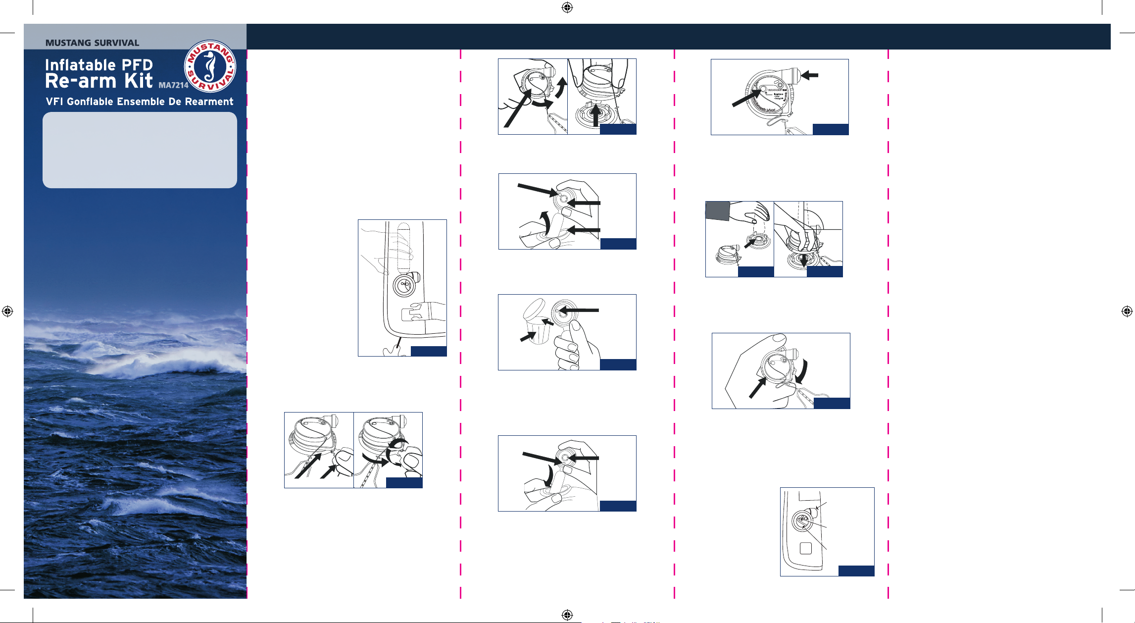
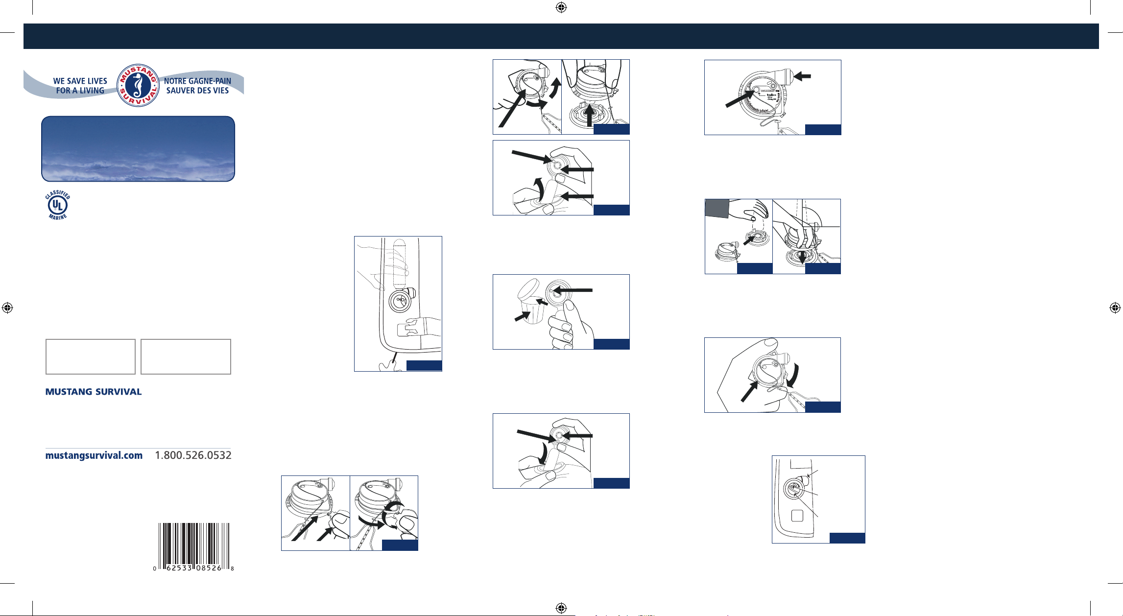
Re-arming instructions
1 Place the Inflatable PFD
(Personal Flotation Device)
on a smooth, flat surface
and wipe off any water.
If needed, unpack the
PFD starting at the zipper
flap. Access the inflator
by reaching between the
cover and cell and pull it
toward you, turning the
cell and cover inside out to
fully expose the inflator for
re-arming. Hold the CO2
cylinder through the fabric,
using one hand (Fig. 1).
Figure 1
CAP
Figure 3
4 Squeeze the sealing ring to elongate and remove the
inflator body through the sealing ring (Fig. 4).
RED
INDICATOR
INFLATOR BODY
SEALING RING
Figure 4
5 Dispose of the used inflator body (Fig. 5).
RED INDICATOR
TRASH
Figure 5
WATER
INLET VALVE
SINGLE
POINT INDICATOR
Figure 7
8 Hold the CO2 cylinder through the fabric of the Inflatable
PFD (Fig 8a). Position the replacement cap with the water
inlet valve pointing to the right and press firmly onto the
inflator body and sealing ring (Fig. 8b).
90º
Figure 8a
Figure 8b
9 While pressing FIRMLY onto the inflator body, turn the
BLACK locking ring clockwise into the locked position (Fig.
9). Pull on the cap to make sure it has locked onto the
inflator body.
tube and check that it stays inflated at least overnight.
Empty the Inflatable PFD again by reversing the oralinflation tube dust cap and inserting it into the valve.
Gently squeeze the inflatable PFD until all air or gas has
been expelled. Let the Inflatable PFD dry before packing.
IMPORTANT: Ensure all air is removed before repacking.
13 Refold the Inflatable PFD in accordance with the repacking
section in the PFD manual.
2 Insert the metal key between the black locking ring and
labeled yellow cap. Turn the key counter-clockwise (Fig. 2).
6 Check that the new inflator body indicator is green. Insert
the new inflator body with CO2 cylinder pointing upward
BLACK
LOCKING RING
Figure 9
inside the Inflatable PFD. Let the sealing ring rest on the
adapter around the four lugs (Fig. 6).
10 Check: To see that the single point status indicator on the
cap is green; the pull to inflate lanyard is present and that
the locking ring is locked.
11 Turn cell and cover right-side out, returning to normal
state. If your PFD has the black molded inflator cap cover
(see Fig. 10), position the protective inflator cap cover
LOCKING RING KEY
Figure 2
GREEN
INDICATOR
CAUTION:
DO NOT TURN
THE CENTER
SHAFT
over the inflator body so
Figure 6
3 Turn the black locking ring counter-clockwise and lift off
the cap (yellow inflator operating head Fig. 3). Dispose of
the used cap.
7 Now check the new manual/automatic cap as follows (Fig. 7):
1. Is the single point status indicator showing green?
2. Is the expiry date OK?
If YES is the answer to both questions, then proceed as
follows. If the answer is NO to either question, get a new cap.
PA7214_Rearm_12Aug2009.indd 1-5 8/25/2009 4:34:07 PM
that the single point status
indicator is visible thrrough
the inflator cap cover
window.
12 If your Inflatable PFD has
been used and/or the
inflator replaced, always
inflate through the oral
Figure 10
mustangsurvival.com
Inflator
Cap Cover
Single Point
Status Indicator
Inflator Cap
Cover Window
FIGURE 8
VFI Gonflable Ensemble De Rearment MA7214
12 Si votre VFI gonflable a été utilisé et/ou que le gonfleur
hydrostatique a été remplacé, toujours gonfler au moyen
du tube buccal et s’assurer qu’il demeure bien gonflé
pendant au moins toute la nuit. Avec le capuchon
protecteur placé sur le tube buccal, serrer doucement
le VFI gonflable jusqu’à ce que tout l’air ou le gaz soit
expulsé. Ne pas tordre le VFI gonflable. Replacer le
capuchon protecteur du tube buccal sur le tube buccal.
Laisser sécher le gilet de sauvetage avant de l’emballer et
de le remiser.
IMPORTANT : S’assurer que tout l’air a été enlevé avant
de réemballer.
13 Replier le VFI gonflable selon les instructions qui se
trouvent à la section réemballage de votre manuel.
Need Help Re-Arming your PFD?
Watch our step-by-step video instructions
at mustangsurvival.com/support
REARMING KIT
FOR USE WITH SPECIFIC PERSONAL FLOTATION DEVICE MODEL
IDENTIFIED ON PRODUCT LABEL.
55HF
For Inflatable PFDs with Hammar MA1 auto hydrostatic
inflator. See product owner’s manual for appropriate re-arm
kit model number.
Kit includes one 33 gram CO2 cylinder/inflator body,
inflator cap, and key.
Pour VFI gonflable avec gonfleur auto-hydrostatique Hammar
MA1. Voir manuel de l’utilisateur pour le bon numéro de
modèle de la trousse de réarmement.
La trousse comprend une cartouche de CO2 de 33 grammes
/corps du gonfleur, un bouchon protecteur, et une clé.
Lot Number / No de lotExpiry / Expiration
AVERTISSEMENT
· Utilisez seulement avec les modèles de VFI spécifiés.
· Ce cylindre de gaz est sous pression donc une mauvaise
utilisation constitue un danger.
· Ne pas incinérer, ni exposer au soleil, ni remiser à des
températures plus élevées que 120˚ F (50˚ C).
· Ne pas jeter au feu ou lancer à la mer.
· Garder hors de portée des enfants.
· Jetez au rebut seulement lorsque les cylindres sont
complètement vides.
· Videz et jetez au rebut les cylindres rouillés ou corrodés.
IMPORTANT: Veuillez réviser et suivre les instructions
d’entretien supplémentaires qui se trouvent dans votre
Manuel de l’usager
Instructions pour réarmer
1 Placer le VFI (vêtement
de flottaison individuel)
gonflable sur une surface
lisse et plate et essuyer le
gilet si nécessaire. Pour avoir
accès au gonfleur, placer
la main sous le couvercle
et tirez-le vers vous, en
retournant la cellule et le
couvercle à l’envers pour
exposer complètement le
gonfleur pour le réarmer.
Capuchon
Indicateur
rouge
ill. 3
Corps du
gonfleur
Anneau
d'étanchéité
ill. 4
4 Serrer l’anneau de blocage pour l’allonger et enlever le
corps du gonfleur par l’anneau de blocage (ill. 4).
5 Jeter le corps du gonfleur usagé (ill. 5).
Indicateur rouge
Poubel
ill. 5
Valve
d'admission
de l'eau
Indicateur
à point unique
ill. 7
8 Tenir la cartouche de CO2 à travers le tissu du VFI
gonflable (ill. 8a). Placer le capuchon de remplacement
avec la valve d’admission d’eau pointant vers la droite, et
appuyer fermement sur le corps du gonfleur et l’anneau
d’étanchéité (ill. 8b).
90º
ill. 8a
ill. 8b
9 Tout en appuyant FERMEMENT sur le corps du gonfleur,
tourner l’anneau de blocage NOIR dans le sens des
aiguilles d’une montre jusqu’à la position de blocage (ill.
17). Tirer sur le capuchon pour s’assurer qu’il est bien
bloqué dans le corps du gonfleur.
Avec une main, tenir la
cartouche de CO2 à travers
le tissu (ill. 1).
ill. 1
2 Insérer la clé métallique entre l’anneau de blocage noir
et le capuchon jaune étiqueté. Tourner la clé dans le sens
Corporate Offices / Bureaux de la société
USA
3870 Mustang Way
Bellingham, WA 98226
Canada
3810 Jacombs Road
Richmond, BC V6V 1Y6
inverse des aiguilles d’une montre (ill. 2).
3 Tourner l’anneau de blocage noir dans le sens inverse des
aiguilles d’une montre (de droite à gauche) et soulever
le capuchon (actionneur jaune du gonfleur (ill. 3). Jeter le
capuchon usagé.
Product of Sweden / Produit de Suède.
Printed in Canada / Packaged in Canada.
Imprimé au Canada / Emballé au Canada.
Mustang Survival and seahorse design
are registered trademarks of Mustang
Survival Corp.
Mustang Survival et design sont des
marques déposées de Mustang
Survival Corp.
PA7214_Rearm_12Aug2009.indd 6-10 8/25/2009 4:34:07 PM
PA7214 (Rev 12Aug2009)
Anneau de
blocage
Clé
ill. 2
6 Vérifier et s’assurer que l’indicateur du corps du gonfleur
est vert. Insérer le nouveau corps du gonfleur à l’intérieur
du VFI gonflable (ill. 6), avec la cartouche de CO2 pointant
vers le haut. Laisser l’anneau de blocage reposer sur
l’adaptateur autour des quatre tenons.
Indicateur
vert
Mise en garde:
ne pas tourner
le manche du
centre
ill. 6
7 Vérifier maintenant le nouveau capuchon manuel/
automatique comme tel (ill. 7):
1. L’indicateur d’état est-il vert?
2. La date d’expiration est-elle correcte?
Si la réponse est OUI dans les deux cas, continuer alors
comme tel. Si la réponse est NON à l’une des questions, se
procurer un nouveau capuchon.
Anneau de
blocage noir
ill. 9
10 Vérifier : Pour s’assurer que l’indicateur d’état sur le
capuchon est vert, que le cordon de gonflage est présent
et que l’anneau de blocage est bloqué.
11 Retourner la cellule et le
couvercle du côté droit,
les retournant à leur état
normal. Si votre VFI est
Couvercle du
capuchon du
gonfleur
Point unique
indicateur de l'étât
muni d'un capuchon pour
gonfleur moulé noir (voir
ill. 10), positionner le
couvercle pour capuchon
Fenêtre du
couvercle de
capuchon pour
gonfleur
du gonfleur protecteur
au dessus du corps du
gonfleur de façon à ce que l'indicateur d'étât soit visible à
travers la fenêtre du couvercle de capuchon pour gonfleur
ill. 10
 Loading...