

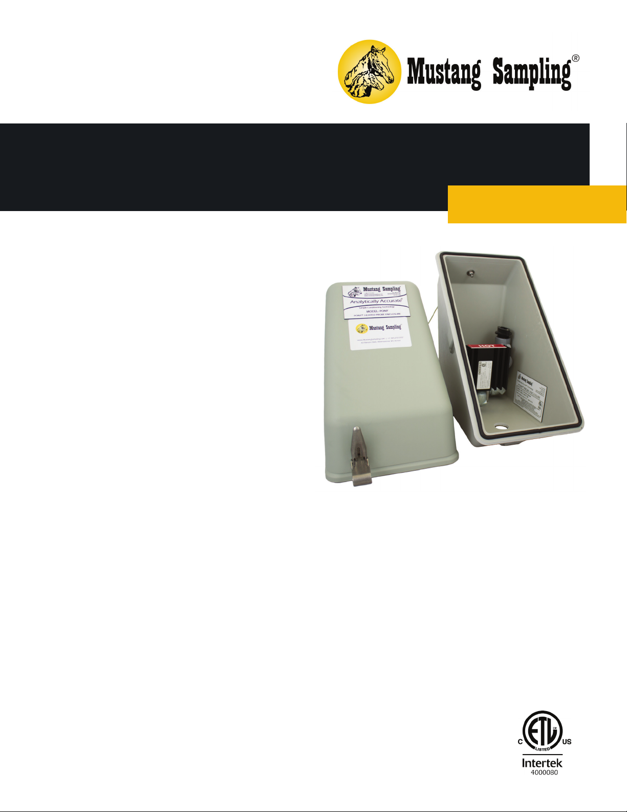
Pony® Heated Probe Enclosure
Installation, Operation & Maintenance
PONY
®

TABLE OF CONTENTS
Safety Warnings 3
Product Features 4
Technical Specifications 5
Product Dimensions & Parts 6
Electrical Wiring Diagrams 8
Installation Instructions 9
Operation Instructions 11
Maintenance Instructions 11
2

SAFETY WARNINGS
Failure to abide by any of the safety warnings
could result in serious injury or death.
• Standard for Safety Electrical Equipment for Measurement, Control, and Laboratory Use; Part 1: General
Requirements (ANSI/UL 61010-1, 07/12/2004, Ed. 2).
• Standard for Safety Electrical Equipment for Measurement, Control , and Laboratory Use; Part 1: General
Requirements (CAN/CSA C22.2 No. 61010-1, 07/01/2004, Ed. 2).
• Standard for Safety Explosion-Proof and Dust-Ignition Proof Electrical Equipment for Use in Hazardous
(Classified) Locations (ANSI/UL 1203, 1028/09, Ed. 4).
• Explosion-Proof Enclosures for Use in Class 1 Hazardous Locations Industrial: Industrial Products (CSA C22.2
No. 30-M1986, (G.I. No. 2, 11/1988)).
• Electrical power must be “OFF” before and during installation and maintenance or personal injury may result.
Follow site requirements for Safety Precaution Rules.
• Do not exceed any equipment pressure, or electrical ratings.
• To reduce the risk of fire or explosion, do not install where the marked operating temperature exceeds the
ignition temperature of the hazardous atmosphere(s).
• Heated regulator surface temperature will approach temperature limit specified in technical specifications.
• Select a mounting location so that the system will not be subjected to impact or other damaging effects.
• The hazard location information specifying class and group listing of each system is marked on the
nameplate.
• Properly ground all equipment to prevent static electric generation.
3

PRODUCT DESCRIPTION
The Pony® Heated Probe Enclosure is an integral patented component of the Mustang®
Sample Conditioning System (MSCS
probe directly at the sample point.
APPLICATION
The Pony enclosure installs between
6” center-to-center threadolets
as an integral component in an
Analytically Accurate® sample
conditioning system.
Pony enclosure models can be
utilized with a remote Mustang®
P53™ Sample Conditioning System
as well as a stand-alone sampling
system.
FEATURES BENEFITS
• Patented technology utilizing
• Molded narrow clam shell design
• Steel latching closures
• Compatible with Mustang
™
) designed to provide and maintain heat for the sample
• Protects probes from temperature
existing power supplied by heat
trace tube bundle
CertiSeries™ line of products
and weather fluctuations
• Helps preserve sample integrity
• Requires no gas consumption or
external power
• Direct-mount on pipeline fitting
between 6” center-to-center
threadolets (TOLs)
• Fits over existing brand of probes
• Provides easy maintenance
4

TECHNICAL SPECIFICATIONS
Heating Components 80 watt self-limiting block heater
Maintains Sample Gas 98ºF (37ºC)
Cabinet Construction Hotpressed Glass Fiber Reinforced Polyester
Input Supply Voltage Options
(optional 50 watt self-limiting block heater for warmer
climates)
120 VAC, 80 Watts
240 VAC, 80 Watts
24 VDC, 25 Watts
5

PRODUCT DIMENSIONS & PARTS
Intertec Enclosure
1
O’Brien Enclosure
1
Item
Number
2
3
1 Insulated Clamshell Enclosure
2 Heat Trace Tube Bundle
3 Self-Limiting Block Heater
4 Probe Location
Description
Connection Location
4
2
3
Stainless Steel Enclosure
1
4
2
3
4
6

Intertec Enclosure
Front View
O’Brien Enclosure
Front View
Stainless Steel Enclosure
Side View
Side View
Front View
Side View
7

ELECTRICAL & WIRING DIAGRAMS
8

INSTALLATION INSTRUCTIONS
NOMENCLATURE
• MAOP—Maximum Allowable Operating Pressure
• LNG—Liquid Natural Gas
• BTU—British Thermal Unit
TOOLS REQUIRED
• Standard Hand Tools
• Utility Knife
INSTALLATION
1. Mount the Pony® Heated Probe Enclosure assembly in accordance with previous cautions and warnings.
2. Perform the electrical hook up with de-energized conductors.
3. Verify the unit that you are hooking up to matches voltage wise with the power supply that you are connecting.
Damage to the unit can occur if the wrong source power is applied.
4. A seal fitting is required for the power input connection to the Pony conduit fitting to maintain its electrical hazard
classification rating.
5. For 120 volt single phase input power: Connect the “hot” wire to wiring terminal #H. Connect the “Neutral” wire
to wiring terminal #N. Connect the earthing (ground) wire to the green screw (G) in the bottom of the enclosure.
6. For 208 or 230 volt single phase input power: Connect one “hot” wire to wiring terminal #H1. Connect the
“Neutral” to wiring terminal #N. Connect the second “hot” wire to wiring terminal #H2. Connect the earthing
(ground) wire to the green screw in the bottom of the enclosure.
7. For 24 VDC input power: Connect the positive wire to wiring terminal #1. Connect the negative wire to wiring
terminal #2. Connect the earthing (ground) wire to the green screw in the bottom of the enclosure.
8. Externally connect earthing (grounding) conductors from assembly to equipment ground connections.
9. After installing the probe housing, tighten the KT-Nut™ down onto the housing.
10. Back the KT-Nut off until the set screw groove is lined up with the set screw.
9

11. Set the Pony
12. Mark the set screw and 4 bolt holes on the bottom of the enclosure.
13. Remove the enclosure from the probe house.
14. Place the yellow cover (provided) over the probe to keep dirt out of the housing.
15. Drill 4 holes into the bottom of the enclosure using a 3/8” drill bit.
16. Place the enclosure onto the housing, and using split washers, bolt the enclosure to the KT-Nut™ with 1/4-20 bolts.
17. Once the enclosure is secured, determine the best place for the Heat Trace Bundle Tube to come into the Pony®
Probe Enclosure. With a 1-1/2” conduit hole saw, drill a hole into the side of the enclosure making sure the lid will
be able to shut.
18. Screw in the Mustang® Heat Trace Tube Bundle seal 1.60 leaving about 5 feet. Mark the tubing bundle and strip
back the black coating and insulation. DO NOT CUT INTO HEAT TRACE. Carefully cut foil coating exposing tubing
and Heat Trace.
19. Slide the 2 legged Raychem TS1-SB2 boot over the tubing and Heat Trace. Heat shrink the boot to the bundle.
20. Pull the bundle through the 1.60 boot leaving 3/4”-1” exposed inside the Pony® Probe Enclosure. Heat shrink the
1.60 boot.
21. With a 1/2” drive ratchet, take the plug out of the seal. Loop the Heat Trace over to the seal and mark the Heat
Trace where it is in the center of the seal.
22. Tape the end of the wires on the Heat Trace and slide the gland with the screws over the Heat Trace followed by
the red grommet.
23. Carefully pull the wires through the seal into the enclosure leaving 1/2”-1” of white core inside the enclosure.
Remove the tape and insert the bus wires into the guide tubes of the CS-100 core sealer. MAKE SURE THE WIRES
ARE NOT CROSSED.
24. Using pin terminals, dead end the circuit into the terminal block provided.
25. NOTE: In the Pony enclosure with Heater Block, you must NOT terminate until you check for polarity and land bus
wires accordingly
®
Heated Probe Enclosure onto the probe housing, lining the enclosure up with the pipe line.
HEAT TRACE TERMINATION
See Mustang Heat Trace Termination Installation Guide.
ADJUST THE TEMPERATURE SET POINT
The heater block is a self limiting heater.
STARTUP PROCEDURE
1. Close the cover on the Pony Heated Probe Enclosure.
2. Allow a few minutes for the system temperature to stabilize.
3. Seal the seal fittings if the Pony Heated Probe Enclosure block heater is functioning as desired.
10

OPERATION INSTRUCTIONS
1. Verify that sample stream supply is shut off.
2. Verify that power to the heat tracing is off.
3. Connect the heat trace tube bundle to the Pony® Probe Enclosure block heater.
4. Turn power on to the heat tracing.
MAINTENANCE INSTRUCTIONS
1. Once system is operational, no routine maintenance is required.
2. Monitoring of flow and temperature values is recommended at least annually.
3. Tape the end of the wires on the Heat Trace and slide the gland with the screws over the Heat Trace followed by
the red grommet.
4. Carefully pull the wires through the seal into the Adalet enclosure leaving 1/2”-1” of white core inside the Adalet
enclosure. Remove the tape and insert the bus wires into the guide tubes of the CS-100 core sealer. MAKE SURE
THE WIRES ARE NOT CROSSED.
5. Using pin terminals, dead end the circuit into the terminal block provided.
6. NOTE: In the Pony® Probe Enclosure with Heater Block, you must NOT terminate until you check for polarity and
land bus wires accordingly.
11

Analytically Accurate
®
TECHNOLOGY
About Mustang Sampling
Mustang Sampling, LLC is
the innovator of Analytically
Accurate® solutions within sample
conditioning systems. We provide
custom solutions of products and
services globally to the Natural
Gas, Natural Gas Liquids (NGL),
and Liquefied Natural Gas (LNG)
industries. Mustang Sampling
continues to pioneer integrated
control systems, allowing our
customers to maintain phase
stability from sample extraction at
the source through sample analysis.
Our products are continuously
improved and subjected to the
highest quality standards which
provides our customers with the
best sample conditioning solutions.
Mustang Sampling, LLC
43 Ritmore Glen
Ravenswood, WV 26164
P: +1 304 273 5357
F: +1 304 273 2531
info@MustangSampling.com
www.MustangSampling.com
Copyright © 2019 Mustang Sampling.
All rights reserved.
Mustang Sampling®, Mustang®, Pony®
and Analytically Accurate® are registered
trademarks of Mustang Sampling, LLC
Watlow® is a registered trademarks of
Watlow.
U.S. Patents 7,162,933; D674,052 S
No part of this publication may be
reproduced in any material form without
the written permission of Mustang
Sampling, LLC.
MS-IOMPONYCS.v3-EN-P
February 2018
Supersedes: MIOMC-PNY-CE 2.1
 Loading...