

Must PV18 MPPT 3 KW, PV18 MPPT 4 KW, PV18 MPPT 5 KW User Manual
3KW~5KW
420-00314-A1

Table of Contents
ABOUT THIS MANUAL .. .. .. ............. .. .. .. .. .. .. .. ............. .. .. .. .. .. .. .. ........... .. .. .. .. .. .. .. ............. ..... .1
Pu rp os e .. ............. .. .. .. .. .. .. ............. .. .. .. .. .. .. .. ........... .. .. .. .. .. .. .. ............. .. .. .. .. .. .. .. ........... .. . . .1
Sc op e .. .. ............. .. .. .. .. .. .. ............. .. .. .. .. .. .. .. ........... .. .. .. .. .. .. .. ............. .. .. .. .. .. .. ............. .. .. ..1
SAFETY INSTRUCTIONS .......... .. .. .. .. .. .. .. ............. .. .. .. .. .. .. .. ........... .. .. .. .. .. .. .. ............. .. .. .. .. ... 1
INTRODUCTION . .. .. .. .. .. .. .. ........... .. .. .. .. .. .. .. ............. .. .. .. .. .. .. .. ........... .. .. .. .. .. .. .. ........... .. .. . . ..2
Features . .. .. .. .. .. .. ............. .. .. .. .. .. .. .. ............. .. .. .. .. .. .. ............. .. .. .. .. .. .. .. ............. .. .. .. .. .. .. .. . ..2
Ba si c Sy st em A rc hi te ct ur e ....... .. .. .. .. .. .. .. ............. .. .. .. .. .. .. ............. .. .. .. .. .. .. .. ........... .. .. .. .. .. ... ..2
Prod uc t Ov er vi ew . ........... .. .. .. .. .. .. .. ............. .. .. .. .. .. .. ............. .. .. .. .. .. .. .. ........... .. .. .. .. .. .. .. ... .. . .3
INSTALLATION . .. .. .. .. .. .. .. ............. .. .. .. .. .. .. ............. .. .. .. .. .. .. .. ............. .. .. .. .. .. .. .. ........... .. ......4
Un pa ck in g an d In sp ec ti on .... .. .. .. .. .. .. .. ............. .. .. .. .. .. .. .. ............. .. .. .. .. .. .. ............. .. .. .. .. .. .. .. . .4
Prep aratio n .. .. .. .. ............. .. .. .. .. .. .. ............. .. .. .. .. .. .. .. ............. .. .. .. .. .. .. .. ........... .. .. .. .. .. .. .. ... .. .4
Mo un ti ng t he U ni t ......... .. .. .. .. .. .. .. ............. .. .. .. .. .. .. ............. .. .. .. .. .. .. .. ........... .. .. .. .. .. .. .. ..........4
Ba tt er y Co nn ec ti on ...... .. .. .. .. .. .. .. ............. .. .. .. .. .. .. .. ........... .. .. .. .. .. .. .. ............. .. .. .. .. .. .. .. ..... ... .5
AC Inp ut / Ou tp ut C on ne ct ion ..... .. .. .. .. .. .. .. ........... .. .. .. .. .. .. .. ............. .. .. .. .. .. .. .. ........... .. .. .. .. ... ..7
Fi na l As se mb ly .......... .. .. .. .. .. .. .. ........... .. .. .. .. .. .. .. ............. .. .. .. .. .. .. .. ............. .. .. .. .. .. .. ....... . ... 12
Co mm un ic at io n Co nn ection .. .. .. .. .. .. .. ............. .. .. .. .. .. .. ............. .. .. .. .. .. .. .. ........... .. .. .. .. .. ... . . ... 12
Dr y Co nt ac t Si gn al ........ .. .. .. .. .. .. .. ........... .. .. .. .. .. .. .. ............. .. .. .. .. .. .. ............. .. .. .. .. .. .. .. ... . ... . 12
OPERATION . . .. ............. .. .. .. .. .. .. ............. .. .. .. .. .. .. .. ........... .. .. .. .. .. .. .. ............. .. .. .. .. .. .. .. ........13
Power ON/OFF . .. .. .. .. ............. .. .. .. .. .. .. .. ........... .. .. .. .. .. .. .. ............. .. .. .. .. .. .. ............. .. .. .. .. .. .. .13
Op eration an d Di sp la y Panel .. .. .. .. .. ........... .. .. .. .. .. .. .. ............. .. .. .. .. .. .. .. ........... .. .. .. .. .. .. .. . . . .... 13
LCD Disp la y Icons .. .. .. .. ............. .. .. .. .. .. .. .. ............. .. .. .. .. .. .. .. ........... .. .. .. .. .. .. .. ............. .. .. .. .. 13
LCD Settin g .. .. .. .. ........... .. .. .. .. .. .. .. ............. .. .. .. .. .. .. ............. .. .. .. .. .. .. .. ........... .. .. .. .. .. .. .. . . ... .14
Fau lt R ef er en ce C od e ............. .. .. .. .. .. .. .. ........... .. .. .. .. .. .. .. ............. .. .. .. .. .. .. .. ............. ... . ... . . ..20
War ni ng Ind icator .. .. .. .. .. .. .. ........... .. .. .. .. .. .. .. ........... .. .. .. .. .. .. .. ............. .. .. .. .. .. .. .. .......... . . . . . .2 2
Op erating Mo de D es cr ip ti on ...... .. .. .. .. .. .. .. ............. .. .. .. .. .. .. .. ........... .. .. .. .. .. .. .. ............. .. . . . . . ..23
Di sp la y Se tt in g .. ............. .. .. .. .. .. .. .. ........... .. .. .. .. .. .. .. ............. .. .. .. .. .. .. .. ............. .. .. .. .. .. .. .. ....23
SPECIFICATIONS . .. .. .. ............. .. .. .. .. .. .. .. ........... .. .. .. .. .. .. .. ............. .. .. .. .. .. .. .. ........... .. .. .. . ... 23
Tabl e 1 Li ne M od e Sp ecification s .. .. .. .. ........... .. .. .. .. .. .. .. ............. .. .. .. .. .. .. .. ........... .. .. .. .. .. .. .. ....24
Tabl e 2 In ve rt er M od e Sp ec if ications .. .. .. .. .. .. ........... .. .. .. .. .. .. .. ............. .. .. .. .. .. .. ............. .. .. .....24
Tabl e 3 Ch ar ge M od e Sp ecification s .. .. .. ............. .. .. .. .. .. .. .. ............. .. .. .. .. .. .. .. ........... .. .. .. .. .. .. .. 26
Tabl e 4 Ge ne ra l Sp ec if ic ations .. .. .. .. .. .. .. ............. .. .. .. .. .. .. .. ........... .. .. .. .. .. .. .. ............. .. .. .. .. .. .. .2 7
TROUBLE SHOOTING . .. .. .. .. .. .. .. ............. .. .. .. .. .. .. ............. .. .. .. .. .. .. .. ........... .. .. .. .. .. .. .. .......... 28
Appendix: Approximate Bac k- up T im e Ta bl e ............. .. .. .. .. .. .. .. ........... .. .. .. .. .. .. .. ............. .. ..29
Appendix: Approximate Back-up Time Table
Model
3KW
4KW
5KW
Note: Backup time depends on the quality of the battery, age of battery and type of battery.
Specifications of batteries may vary depending on different manufacturers.
Load(W) Backup Time@48Vdc 100Ah(min) Backup Time@48Vdc 200Ah(min)
300
600
900
1200
1500
1800
2100
2400
2700
3000
400
800
1200
1600
2000
2400
2800
3200
3600
4000
500
1000
1500
2000
2500
3000
3500
4000
4500
5000
1054
491
291
196
159
123
105
91
71
63
766
335
198
139
112
95
81
62
55
50
613
268
158
111
90
76
65
50
44
40
2107
1054
668
497
402
301
253
219
174
155
1610
766
503
339
269
227
176
140
125
112
1288
613
402
271
215
182
141
112
100
90
29

TROUBLE SHOOTING
Problem
Unit shuts down
automatically during
startup process.
No response after
power on.
Mains exist but the
unit works in battery
mode.
When the unit is
turned on, internal
relay is switched on
and off repeatedly.
Buzzer beeps
continuously and
red LED is on.
LCD/LED/Buzzer
LCD/LEDs and buzzer
will be active for 3
seconds and then
complete off.
No indication.
Input voltage is
displayed as 0 on the
LCD and green LED
is flashing.
Green LED is flashing.
LCD display and LEDs
are flashing
Fault code 07
Fault code 05
Fault code 02
Fault code 03
Fault code 01
Fault code 06/58
Fault code
08/09/53/57
Fault code 51
Fault code 52
Fault code 55
Fault code 56
Explanation / Possible cause
The battery voltage is too low
( < 1.91V/Cell)
1. The battery voltage is far too low.
(<1.4V/Cell)
2. Battery polarity is connected
reversed. Input protector is tripped
1. Re-charge battery.
2. Replace battery.
1. Check if batteries the wiring
are connected and well.
2. Re-charge battery.
3. Replace battery.
Check if AC breaker is tripped
Input protector is tripped
and AC wiring is connected
well.
1. Check if AC wires are too
thin and/or too long.
Insufficient quality of AC power
(Shore or Generator)
2. Check if generator (if
applied) is working well or if
input voltage range setting is
correct.(Appliance=>wide)
Battery is disconnected.
Overload error. The inverter is
overload 110% and time is up.
Check if battery wires are
connected well.
Reduce the connected load by
switching off some equipment.
Check if wiring is connected
Output short circuited.
well and remove abnormal
load.
Check whether the air flow of
Internal temperature of inverter
component is over 90 C.
o
Battery is over-charged.
The battery voltage is too high.
the unit is blocked or whether
the ambient temperature is too
high.
Return to repair center.
Check if spec and quantity of
batteries are meet
requirements.
Fan fault Fan fault
Output abnormal (Inverter voltage
below than 202Vac or is higher than
253Vac)
Internal components filed.
Over current or surge
Bus voltage is too low
Output voltage is unbalanced
Battery is not connected well or
fuse is burnt.
1. Reduce the connected load.
2. Return to repair center
Return to repair cente
Restart the unit, if the error
happens again, please return
to repair center.
If the battery is connected well,
please return to repair center.
What to do
ABOUT THIS MANUAL
Purpose
This manual describes the assembly, installation, operation and troubleshooting of this unit. Please read this manual
carefully before installations and operations. Keep this manual for future reference.
Scope
This manual provides safety and installation guidelines as well as information on tools and wiring.
The following cases are not within the scope of warranty
1. Out of warranty.
2. Series number was changed or lost.
3. Battery capacity was declined or external damaged.
4. Inverter was damaged caused of transport shift, remissness, ect external factor
5. Inverter was damaged caused of irresistible natural disasters.
6. Not in accordance with the electrical power supply conditions or operate environment caused damage.
SAFETY INSTRUCTIONS
WARNING: This chapter contains important safety and operating instructions. Read and keep
this manual for future reference.
1. Before using the unit, read all instructions and cautionary markings on the unit the batteries and all appropriate
sections of this manual.
2. CAUTION --To reduce risk of injury, charge only deep-cycle lead acid type rechargeable batteries. Other types
of batteries may burst, causing personal injury and damage.
3. Do not disassemble the unit. Take it to a qualified service center when service or repair is required. Incorrect
re-assembly may result in a risk of electric shock or fire.
4. To reduce risk of electric shock, disconnect all wirings before attempting any maintenance or cleaning. Turning
off the unit will not reduce this risk.
5. CAUTION --Only qualified personnel can install this device with battery.
6. NEVER charge a frozen battery.
7. For optimum operation of this inverter/charger, please follow required spec to select appropriate cable size. It' s
very important to correctly operate this inverter/charger.
8. Be very cautious when working with metal tools on or around batteries. A potential risk exists to drop a tool to
spark or short circuit batteries or other electrical parts and could cause an explosion.
9. Please strictly follow installation procedure when you want to disconnect AC or DC terminals. Please refer to
INSTALLATION section of this manual for the details.
10. Fuses (1 piece of 200A, 58VDC for 3KW,4KW and 5KW) are provided as over-current protection for the battery
supply.
11. GROUNDING INSTRUCTIONS- This inverter/charger should be connected to a permanent grounded wiring
system. Be sure to comply with local requirements and regulation to install this inverter.
12. NEVER cause AC output and DC input short circuited. Do NOT connect to the mains when DC input short circuits.
13. Warning!! Only qualified service persons are able to service this device. If errors still persist after following
troubleshooting table, please send this inverter/charger back to local dealer or service center for maintenance.
28
1
INTRODUCTION
This is a multi-function inverter/charger, combining functions of inverter, solar charger and battery charger to offer
uninterruptible power support with portable size. Its comprehensive LCD display offers user-configurable and
easy-accessible button operation such as battery charging current, AC/solar charger priority, and acceptable input
voltage based on different applications.
Features
Pure sine wave inverter
Configurable input voltage range for home appliances and personal computers via LCD setting
Configurable battery charging current based on applications via LCD setting
Configurable AC/Solar Charger priority via LCD setting
Compatible to mains voltage or generator power
Auto restart while AC is recovering
Overload/ Over temperature/ short circuit protection
Smart battery charger design for optimized battery performance
Cold start function
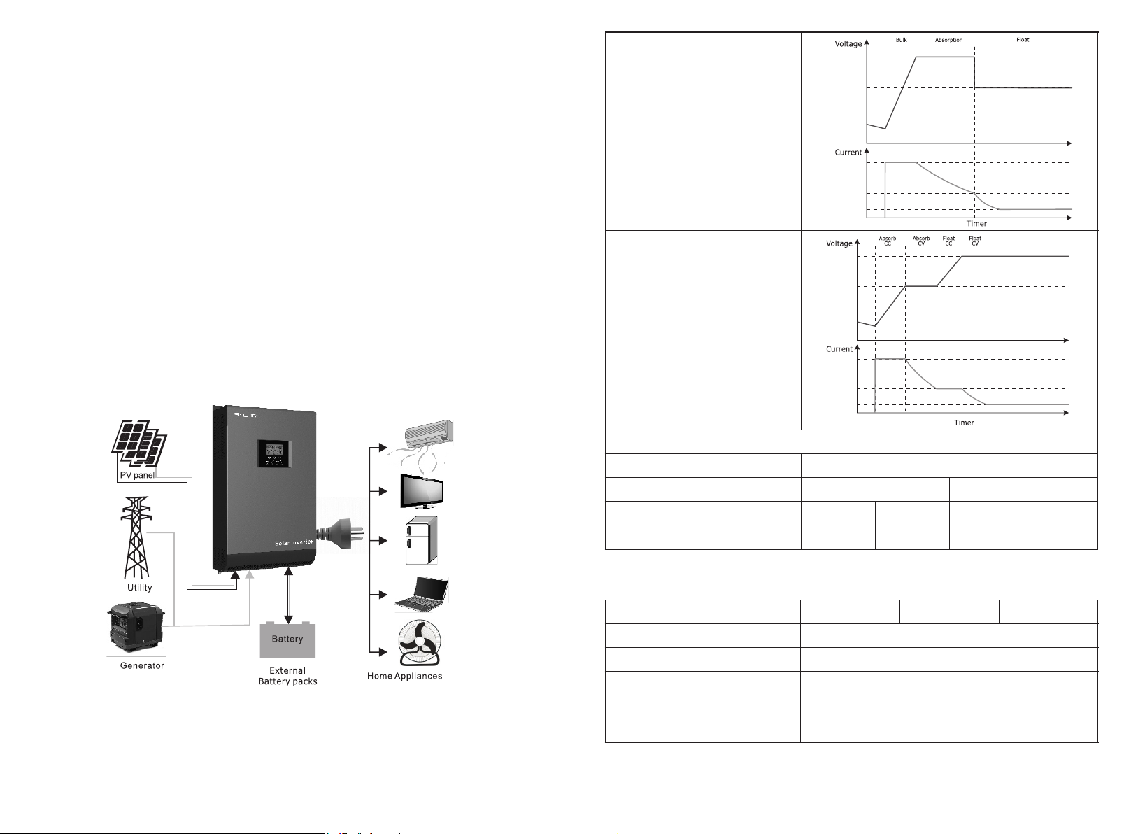
Basic System Architecture
The following illustration shows basic application for this inverter/charger. It also includes following devices to have
a complete running system:
Generator or Utility.
PV modules (option)
Consult with your system integrator for other possible system architectures depending on your requirements.
This inverter can power all kinds of appliances in home or office environment, including motor-type appliances such
as tube light, fan, refrigerator and air conditioner.
Charging algorithm for
lead acid battery
Charging algorithm for
Lithium battery
Figure 1 Hybrid Power System
2
Joint Utility and Solar Charging
INVERTER MODEL
Max Charging Current
Default Charging Current
Table 4 General Specications
INVERTER MODEL
Safety Certication
Operating Temperature Range
Storage temperature
Dimension (D*W*H), mm
Net Weight, kg
MPPT charger
120A
60A
3KW
27
3KW~5KW
140A
80A
4KW
CE
0°C to 55°C
-15°C~ 60°C
488 x 295 x 141
10.0
PWM charger
120A
60A
5KW

Low DC Cut-off Voltage
@ load < 20%
@ 20% ≤ load < 50%
@ load ≥ 50%
High DC Recovery Voltage
High DC Cut-off Voltage
No Load Power Consumption
Table 3 Charge Mode Specications
Utility Charging Mode
INVERTER MODEL
Charging Current @ Nominal Input
Voltage
Absorption
Voltage
Reoat
Voltage
Float
Voltage
Charging Algorithm
Solar Charging Mode
INVERTER MODEL
Rated Power
MPPT charger
solar charging current
Max.PV Array Open Circuit Voltage
PV Array MPPT Voltage Range
Min battery voltage for PV charge
PWM charger
solar charging current
Operating Voltage Range
Max.PV Array Open Circuit Voltage
Standby Power Consumption
Battery Voltage Accuracy
PV Voltage Accuracy
Charging Algorithm
AGM / Gel/LEAD
Battery
Flooded battery
AGM / Gel/LEAD
Battery
Flooded battery
AGM / Gel/LEAD
Battery
Flooded battery
42.0Vdc
40.8Vdc
38.4Vdc
58Vdc
60Vdc
<50W
3KW~5KW
1~60A
50Vdc
50Vdc
54.8Vdc
54.8Vdc
57.6Vdc
56.8Vdc
33-Step(Flooded Battery,AGM/Gel/LEAD Battery),4-Step(LI)
3KW~5KW
3000W 4000W
60A
145Vdc max
64~130Vdc
34Vdc
60A
60~72Vdc
105Vdc
2W
+/-0.3%
+/-2V
3-Step(Flooded Battery,AGM/Gel/LEAD Battery), 4-Step(LI)
80A
Product Overview
3KW-5KW parallel model
NOTE: For parallel model installation and operation,
please check separate parallel installation guide for
the details.
3KW-5KW single model
1. LCD display
2. Status indicator
3. Charging indicator
4. Fault indicator
5. Function buttons
6. Power on/off switch
7. AC input
8. AC output
9. PV input
10. Battery input
11. Circuit breaker
12. RS485 communication port
13. Parallel communication port (only for parallel model)
14. Parallel switch
15. Dry contact
16. USB
26
3
 Loading...