

Must EP33-1024TLV, EP33-1512TLV, EP33-1012TLV, EP33-2012TLV, EP33-1524TLV User Manual
...
INVERTER/CHARGER
1012/1024/1512/1524/2012/2024/3024/3048
4024/4048/5048/6048
Appliances
PC TV
Air-
conditioning
Fridge
Washing
machine

TABLE OF CONTENTS
Ge ne ra l Pr ec au tions...... .. .. ............. .. .. ........... .. .. .. ........... .. .. ........... .. .. .. ........... ..... .1
Personne l Pr ec au tions...... .. .. ........... .. .. .. ........... .. .. ........... .. .. .. ........... .. .. ........... .....1
Intr od uc ti on......... .. .. ........... .. .. .. ........... .. .. ........... .. .. .. ........... .. .. ........... .. .. .. .........2
Featu re s. .. .. .. ........... .. .. ............. .. .. ........... .. .. ............. .. .. ........... .. .. ............. .. .. ...2
Prod uc t Ov er view.. .. ........... .. .. .. ........... .. .. ............. .. .. ........... .. .. ............. .. .. ........... 2
LCD Pan el D es cription. ............. .. .. ........... .. .. ............. .. .. ........... .. .. ............. .. .. ........2
Ba ck panel prin ti ng d es criptio n. .. ........... .. .. ........... .. .. .. ........... .. .. ............. .. .. .............3
Si de panel pr in ti ng d escriptio n. .. ........... .. .. .. ........... .. .. ............. .. .. ........... .. .. ............. 3
AC terminal p an el p ri nting descr ip ti on .... .. .. .. ........... .. .. ........... .. .. .. ........... .. .. ...............4
Inst al la tion....... .. .. ........... .. .. .. ........... .. .. ........... .. .. .. ........... .. .. ........... .. .. .. ............4
Un packing a nd i ns pe ction......... .. .. .. ........... .. .. ........... .. .. .. ........... .. .. ........... .. .. .. .......4
Prepara ti on .... .. .. ........... .. .. .. ........... .. .. ........... .. .. .. ........... .. .. ............. .. .. ........... .. 4
Mo unting th e Un it .. .. .. ........... .. .. .. ........... .. .. ........... .. .. .. ........... .. .. ........... .. .. .. ........4
Op erat io n. .. ........... .. .. ........... .. .. .. ........... .. .. ........... .. .. .. ........... .. .. ........... .. ...... .....8
Op erati on k ey instruct io ns .. .. .. ........... .. .. .. ........... .. .. ........... .. .. .. ........... .. .. ....... ........ 8
Se tting key i ns tr uctions .. ........... .. .. ........... .. .. .. ........... .. .. ........... .. .. .. ......... ... ... .. .....8
LCD displ ay........ .. .. ......... .. .. .. ......... .. .. .. ....... .. .. .. ......... .. .. .. ....... .. .. .. ......... .. .. .. ......... ... ......10
Op erati ng m od e de scripti on .. .. ......... .. .. .. ......... .. .. ......... .. .. .. ......... .. .. ......... .. .. .. ....................11
AG S fu nc ti on ........... .. .. ............. .. .. ........... .. .. ............. .. .. ........... .. .. ............. .. .......11
A GS functi on i nf ormation. ........... .. .. .. ........... .. .. ............. .. .. ........... .. .. ............. .. .. ...11
Dr y contact o pe rating vo lt ag e... .. .. ........... .. .. ............. .. .. ........... .. .. ............. .............12
BTS function.... .. .. ........... .. .. ............. .. .. ........... .. .. .. ........... .. .. ........... .. .. .. ............12
BTS f un ct ion descrip ti on .. .. .. .. ........... .. .. ............. .. .. ........... .. .. ............. .. .. ..............12
Co nnect inv er te r and batte ry .. .. .. ........... .. .. ............. .. .. ........... .. .. ............. .. .. ...........1 2
Co mm un ication...... .. .. ........... .. .. ........... ... .. .. ........... .. .. .. ........... .. .. ........... ..... .....1 2
Up per Compu te r Mo ni toring dire ct io ns .... .. .. .. ........... .. .. ........... .. .. .. ........... .. .. ............1 2
T he o perat io n st ep s are as fo ll ow s... .. .. ........... .. .. .. ........... .. .. ........... .. .. .. ...................12
Sp ec if ications... .. .. ............. .. .. ........... .. .. ............. .. .. ........... .. .. .. ........... .. .. ...........1 4
Inverter M od e Sp ecification .. .. ............. .. .. ........... .. .. .. ........... .. .. ........... .. .. ..........14
A C Mo de S pe cification. .. .. ........... .. .. ............. .. .. ........... .. .. ............. .. .. ................15
Charge Mode Spe ci fi cations.... .. .. .. ........... .. .. ........... .. .. .. ........... .. .. ............ .........15
Fau lt Mode........ .. .. ........... .. .. ............. .. .. ........... .. .. ............. .. .. ........... .. .. ........16
Trouble shootio ng . .. ........... .. .. .. ........... .. .. ........... .. .. .. ........... .. .. ........... .. .. .. .........17

WARNING!
This manual contains important instructions for all Inverter/Charger models that shall be
followed during installation and maintenance of the inverter.
The following cases are not within the scope of warranty
1. Out of warranty.
2. Series number was changed or lost.
3. Battery capacity was declined or external damaged.
4. Inverter was damaged caused of transport shift, remissness, ect external factor
5. Inverter was damaged caused of irresistible natural disasters.
6. Not in accordance with the electrical power supply conditions or operate environment
caused damage.
General Precautions
Before using it, read all instructions and markings:
(1) inverter (2) battery (3) user manual
CAUTION:
To reduce risk of injury, charge only lead-acid rechargeable batteries. If customer use flooded batteries, batteries 1.
must be maintained regularly. Other battery types may cause damage and injury.
Do not expose it to rain, snow or any type liquids. Inverters are designed for indoor use.2.
3. Do not disassemble it. Take it to qualified service center when service or repair is needed.
4. To prevent the risk of electric shock, disconnect all wiring before attempting any maintenance or cleaning. Only
turning off the unit will not reduce the risk.
WARNING:
1. Provide ventilation from the battery compartment to outdoors. The battery enclosure should be designed to
prevent accumulation and concentration of hydrogen gas at the top of the compartment.
2. NEVER charge a frozen battery and connect such 12V/24V/48V batteries to inverter.
3. Input/output AC wiring mustn’t be less than 12AWG and not rated for 75 °C or higher. Battery cable mustn’t be
rated for 75°C or higher and should be no less than 4AWG /6AWG gauge.
4. Pay special attention when working with metal tools around batteries. Batteries short-circuiting could cause an
explosion.
5. Read the battery installation and maintenance instructions carefully before operating.
Personnel Precautions
1. Better to prepare plenty of fresh water and soap nearby in case battery acid contacts skin, clothing or eyes.
2. Avoid touching eyes while working near batteries.
3. NEVER smoke or allow a spark or flame near batteries.
4. Remove personal metal items such as rings, bracelets, necklaces, and watches when working with batteries.
Batteries may provide heavy short-circuit current, which would be enough to make metal melt and causes severe
burn.
5. If a remote or automatic generator start system is used, disable the automatic starting circuit or disconnect the
generator to prevent accident during servicing
-1-
Introduction
This inverter is applicable to different markets demands, it matches different voltage AC 120V/240V, also can set
output voltage, frequency, charging voltage, charging current, it’s available to work in split phase power
environment.
Features:
Pure sine wave output·
Friendly user interface·
3 Steps charging·
MFD (multi-function display)·
Overload and short-circuit protection·
Set charging voltage/charging current.·
Battery low voltage shutdown point can be set to 10/10.5/11V·
Power-save mode·
Set utility priority/ Battery priority·
Set utility input wide/narrow range·
Inverter voltage can be set to 110/115/120·
Inverter frequency can be set to 50/60Hz·
Set utility charging on/off switch·
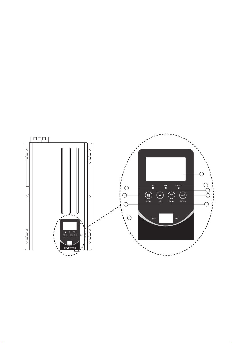
LCD Panel Description
9
1. Switch ON/OFF: POWER ON/OFF Switch
2. MENU
3. UP
4. DOWN
5. ENTER
-2-
6
2
3
1
8
7
5
4
INVERTER
6. AC LED
7. INV LED
8. FAULT
9. LCD
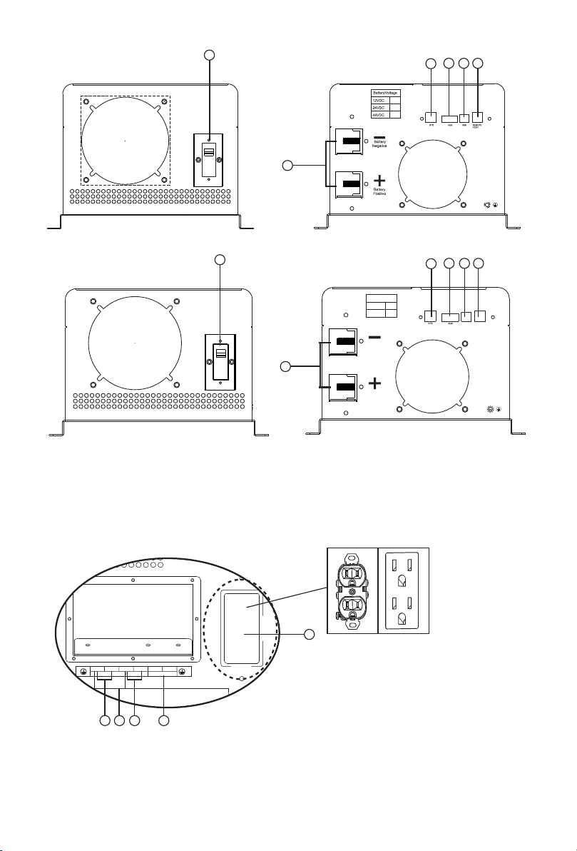
Back panel printing description:
AC OUTPU T
120V/1 5A MAX
AC OUTP UT AC INTP UT
HOT1
HOT2
N
HOT2HOT1
N
6
ACINPUT
PROTECT
5
2
4
3
1
1-3K Back Panel
6
Battery Voltage
24VDC
AC INPUT
PROTECT
1
48VDC
Battery
Negative
Battery
Positive
5 2
4
3
REMOTE
USB
PORT
4-6K Back Panel
1. Battery -/+
2. REMOTE PORT
3. BTS
4. AGS
Side panel printing description:
1
3
4
2
AC Side Panel
5. USB
6. AC INPUT PROTECT: Input protect breaker
5
1. AC OUTPUT:HOT1 -N120VAC/110 VAC/115VAC
2. AC OUTPUT: HOT2 -N120VAC/110 VAC/115VAC
3. AC OUTPUT:HOT1 -HOT2240VAC/220 VAC/230VAC
4. AC INPUT:HOT1 -HOT2240VAC/220 VAC/230VAC
5.15AMAX JFCI/NEMA 5-15R Output 110V/115V/120V Socket
-3-
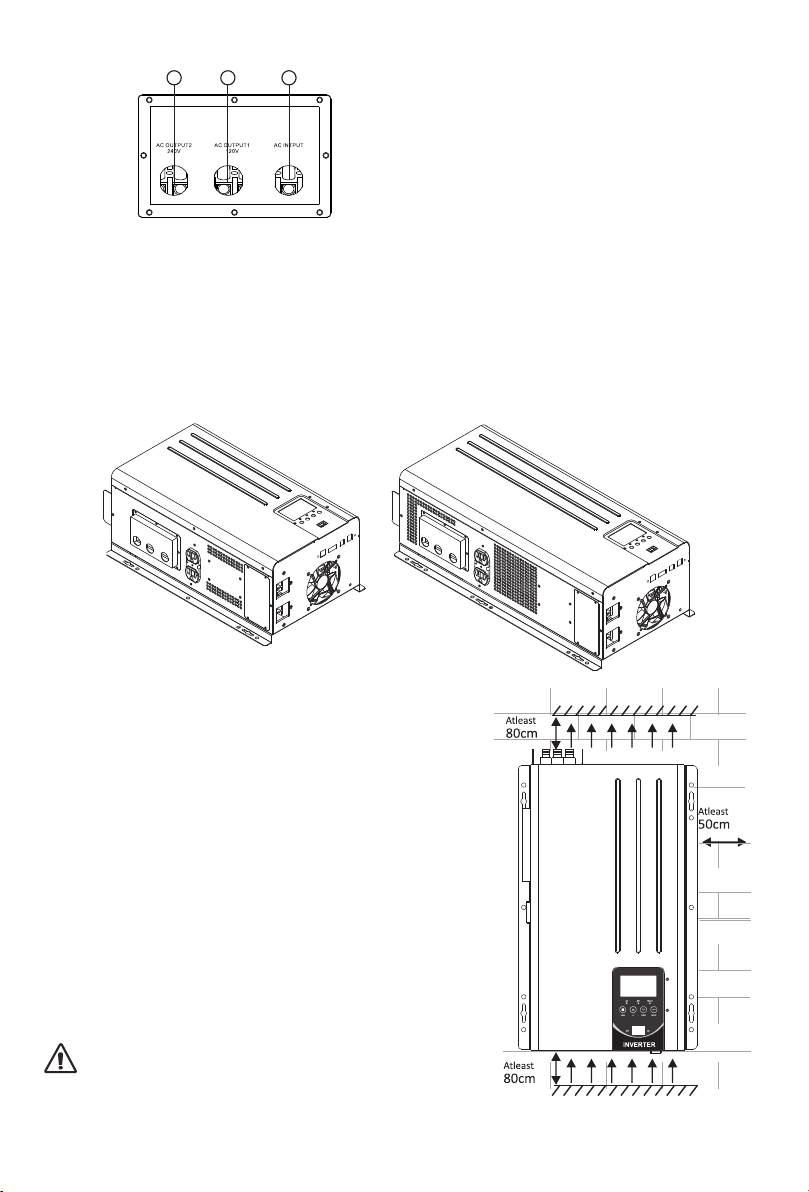
AC terminal panel printing description
1
2
3
1. AC OUTPUT2 220V/230V/240V CLIP
2. AC OUTPUT1 110V/115V/120V CLIP
3. AC INPUT 220V/230V/240V CLIP
Installation
AC terminal panel
Unpacking and inspection
Before installation, please inspect whole unit. Be sure that nothing inside the package is damaged. You should have
received the following items inside of package.
User manual X 1 Software CD X 1
Communication cable X 1 Battery cables (RED/BLACK) X 2
Preparation
Before connecting all wirings, please take off bottom cover by removing eight screws as shown below:
Mounting the Unit
Consider the following points before selecting where to install:
·Do not mount the inverter on flammable construction
materials.
·Mount on a solid surface.
·Install this inverter at eye level in order to read the
LCD display clearly.
·For proper air circulation to dissipate heat, require a
clearance about 50 cm to the side and 80 cm above
and below the unit.
·The ambient temperature should be between 0 C and
o
40 C to ensure optimal operation.
o
·The recommended installation position is to be
adhered to the wall vertically.
·Be sure to keep other objects and surfaces as shown
in the diagram to guarantee sufficient heat dissipation
and to have enough space for removing wires.
SUITABLE FOR MOUNTING ON
CONCRETE OROTHER NON-COMBUSTIBLE
SURFACE ONLY.
-4-
 Loading...