

Must PH30, 9KW, 12KW User Manual
9KW-12KW


Table Of Contents
ABOUT THIS MANUAL..................................................................................................................1
SAFETY INSTRUCTIONS...............................................................................................................1
PRODUCT INTRODUCTION .........................................................................................................2
Features..................................................................................................................................2
Basic System Architecture.........................................................................................................2
Product Overview ....................................................................................................................3
Packing List ............................................................................................................................3
User Environment ...................................................................................................................4
INSTALLATION ...........................................................................................................................4
Preparation ............................................................................................................................4
Battery Connection .................................................................................................................4
PV Connection.........................................................................................................................6
GRID / AC OUTPUT(LOAD) Connection......................................................................................7
Three-Phase Unit Connection................................................................................................8
Single-Phase Unit Connection...............................................................................................8
Grounding Connection..............................................................................................................9
Final Assembly........................................................................................................................9
Communication and BTS Connection........................................................................................10
Communication Connection.................................................................................................10
BTS Connection..................................................................................................................10
OPERATION...............................................................................................................................11
Operation and Display Panel....................................................................................................11
LCD Display Icons...................................................................................................................12
Commissioning.......................................................................................................................14
LCD Setting............................................................................................................................16
Display Setting ......................................................................................................................22
Operating State Description....................................................................................................24
Fault Reference Code.............................................................................................................25
Warning Indicator...................................................................................................................27
SPECIFICATIONS.......................................................................................................................28
Table 1 Line Mode Specifications..............................................................................................28
Table 2 Inverter Mode Specifications .......................................................................................29
Table 3 Charge Mode Specifications ........................................................................................30
Table 4 General Specifications..................................................................................................31
TROUBLE SHOOTING ................................................................................................................32
APPENDIX: APPROCIMATR BACK-UP TIME TABLE.........................................................................34
ABOUT THIS MANUAL
Purpose
Th is m an ua l de sc ri be s th e as se mb ly, insta ll at io n an d tr ou bl es ho ot in g of t hi s un it . Pl ea se
read thi s ma nu al c ar efully before installati on s an d op erations. Keep this manual for fu tu re
reference.
Scope
Th is m an ua l pr ov id es s afety and installation gui de li ne a s we ll a s in fo rm at io n on t oo l an d
wi ri ng .
SAFETY INSTRUCTIONS
Be fo re using the i nverter, pl ea se r ea d al l in st ru ct io ns a nd c au ti on ary markings on the unit
an d th is m an ua l. S to re t he m an ua l wh er e it c an b e ac ce ss ed e as il y.
CAUTION-To reduce rise of injur y, charge only deep-cycle lead acid type rechargeable
ba tterie s. O th er types of ba tteries may burst, causi ng p er so na l in ju ry a nd d am ag e.
Do n ot d is as se mb le t he u ni t. Take it to a qualified service center when service or repair is
requ ired. Incorrect re-assemble may result in a risk of electric sho ck o r fi re .
To red uc e ri sk of electric shock, disconnect all wirings before attempting any maintenance
or c le an in g. Turning off the unit will not reduce this risk.
CAUION - Only qualified person ne l ca n in st al l th is d ev ic e wi th b at te ry.
NEVER charger a frozen battery.
For optimum operation of this energy storage inve rt er, pl ea se follow required spec to select
ap pr op ri at e ca bl e si ze . It s very important to correctly operat e th is energy storag e in vert er.
Be ver y ca ut io us w he n wo rk in g wi th m et al t ools on or aro und batt er ie s. A potential risk
ex is ts t o dr op a t oo l to s pa rk o r sh or t ci rc ui t ba tt er ie s or o th er e le ct rical parts and could
ca us e an e xp lo si on .
Pl ea se s tr ic tl y fo ll ow i ns ta ll at io n pr oc ed ur e wh en y ou w an t to d is co nn ec t AC o r DC
te rm in al s, P le as e re fe r to I NS TAL LAT IO N se ct io n of t hi s ma nu al f or t he b at te ry s up pl y.
Fu se 2 p ie ce s of 2 00 A, 5 8V DC f or 9 KW, 3pieces of 2 00 A, 5 8V DC for 12K W, are provided as
over-current protection for the battery supply.
GR OU ND IO N IN ST RU CT IO NS -T hi s en er gy s to rage inverter should be connected to a
pe rm an en t gr ou nd ed W ir in g sy st em . Be sure to compl y with local req uirement s and re gulation
to i ns ta ll t hi s in verter.
NEVER cause AC output and DC input short circuit e. D o NOT connect to the mains when
DC i np ut s ho rt c ir cu it s.
Warning!! Only qualified service per so ns a re a bl e to s er vi ce t hi s de vi ce . If e rr or s st il l
pe rs is t af te r fo ll ow in g tr ou bl es ho ot in g ta bl e, p le as e send this energy stora ge i nv er te r ba ck
to l oc al d ea le r or s er vi ce c en te r fo r ma in te na nc e.
,
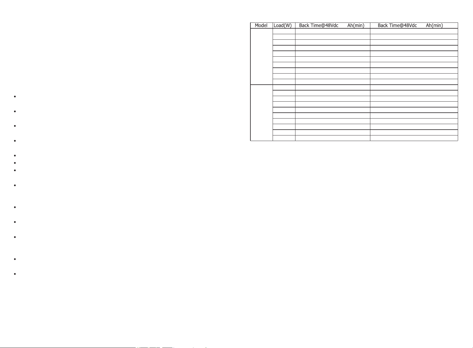
APPENDIX: APPROCIMATR BACK-UP TIME TABLE
40 0 60 0
90 0
18 00
27 00
36 00
9K W
45 00
54 00
63 00
72 00
81 00
90 00
12 00
24 00
36 00
48 00
12 KW
60 00
72 00
84 00
96 00
10 80 0
12 00 0
Notice: Bac kup time depe nds on the quality of th e batter y,age of battery and type of batte ry.
Sp ec if ic at io ns of batteries may va ry d epending on different manufacturers.
10 82
48 4
31 1
21 3
17 0
14 2
11 3
99
88
68
81 1
36 3
21 3
14 9
11 9
85
73
64
56
51
16 74
81 1
50 1
36 3
27 3
21 3
18 3
14 9
13 2
10 2
12 17
56 3
36 3
25 6
19 2
14 9
10 9
96
85
76
- 1 -
- 3 4 -

Fault code 80 CAN data loss
Fault code 81 Host data loss
Fault code 82
Fault code 83
Fault code 84
Fault code 85
Fault code 86
Fault code 87
Fault code 88
Fault code 89
Fault code 90
Synchronization data loss
The battery voltage of
each inverter isnot
the same.
AC input voltage and
frequency are
detected different
AC output current
unbalance
AC output mode setting
is different
Current feedback into the
inverter is detected.
The firmware version of
each inverter is not the
same.
The output current of each
inverter is different.
CAN ID setting Error
1.Check if communication
cables are connected well
and restart the inverter.
2.If the problem remains,
please contact your installer.
1.Make sure all inverters s
hare same groups of
batteries together.
2.If the problem remains,
please contact your installer.
1.Check the grid wiring
conncetion and restart the
inverter.
2.If the problem remains,
please contact your installer.
1.Restart the inverter.
2.If the problem remains,
please contact your installer
1.Switch off the inverter
and check the DIP switch
setting.
2.If the problem remains,
please contact you installer.r
1.Restart the inverter.
2.If the problem remains,
please contact your installer.
1.Update all inverter firmware
to the same version.
2.If the problem remains,
please contact your installer.
1.Check if sharing cables are
connected well and restart
the inverter.
2.If the problem remains,
please contact your installer.
1.Switch off the inverter and
check the DIP switch setting.
2.If the problem remains,
please contact your installer.
PRODUCT INTRODUCT IO N
Th is i s a mu lt i- fu nc ti on E ne rg y St orage Inverter, combining functions of inve rter, O n- Gr id ,
MP PT s ol ar c ha rg er a nd b at te ry c ha rg er t o of fer un in te rr up ti bl e po we r su pp or t. I t' s
co mp re he ns iv e LCD display offers user-configurable and easy-a cc es si bl e bu tt on o pe ration
su ch a s ba tter y ch ar gi ng c ur re nt , AC /s ol ar c ha rg er p ri or it y, a nd a cc ep ta bl e in pu t vo lt ag e
ba se d on d if ferent applica ti on s.
Features
Pu re sin e wave inverter.
Bu il t-in MPPT sola r ch arge c on tr ol le r.
On -g ri d Inverter with Energy Storage.
Se le ct ab le i np ut v ol ta ge range for home applianc es a nd p er so na l co mp ut er s LC D se tt in g.
Se le ct ab le b at te ry c ha rg in g cu rr en t ba se d on a pp li ca ti on s vi a LC D se tt in g.
Se le ct ab le M ul ti pl e ap pl ic at io n modes: Load priority mode, Math load mode, Sell mode,
Ba ck up U PS m od e an d Of f gr id p ri or it y mo de .
Auto restart whi le A C is r ec overing.
Sm ar t ba tter y ch arge d es ig n for opti mi ze d ba ttery performance.
Mu lt ip le c om mu ni ca ti on f or R S- 48 5 an d CA N BU S.
Overload and s ho rt c ir cu it p ro te ct io n.
Basic System Archit ec tu re
Th is e ne rg y st orage inverter can provide Po we r to connected loads by utilizing PV power,
gr id p ow er a nd b at te ry p ow er.
External
Battery pack
Grid
- 3 3 -
PV panel
PV panel PV panel
Home Appliances
- 2 -
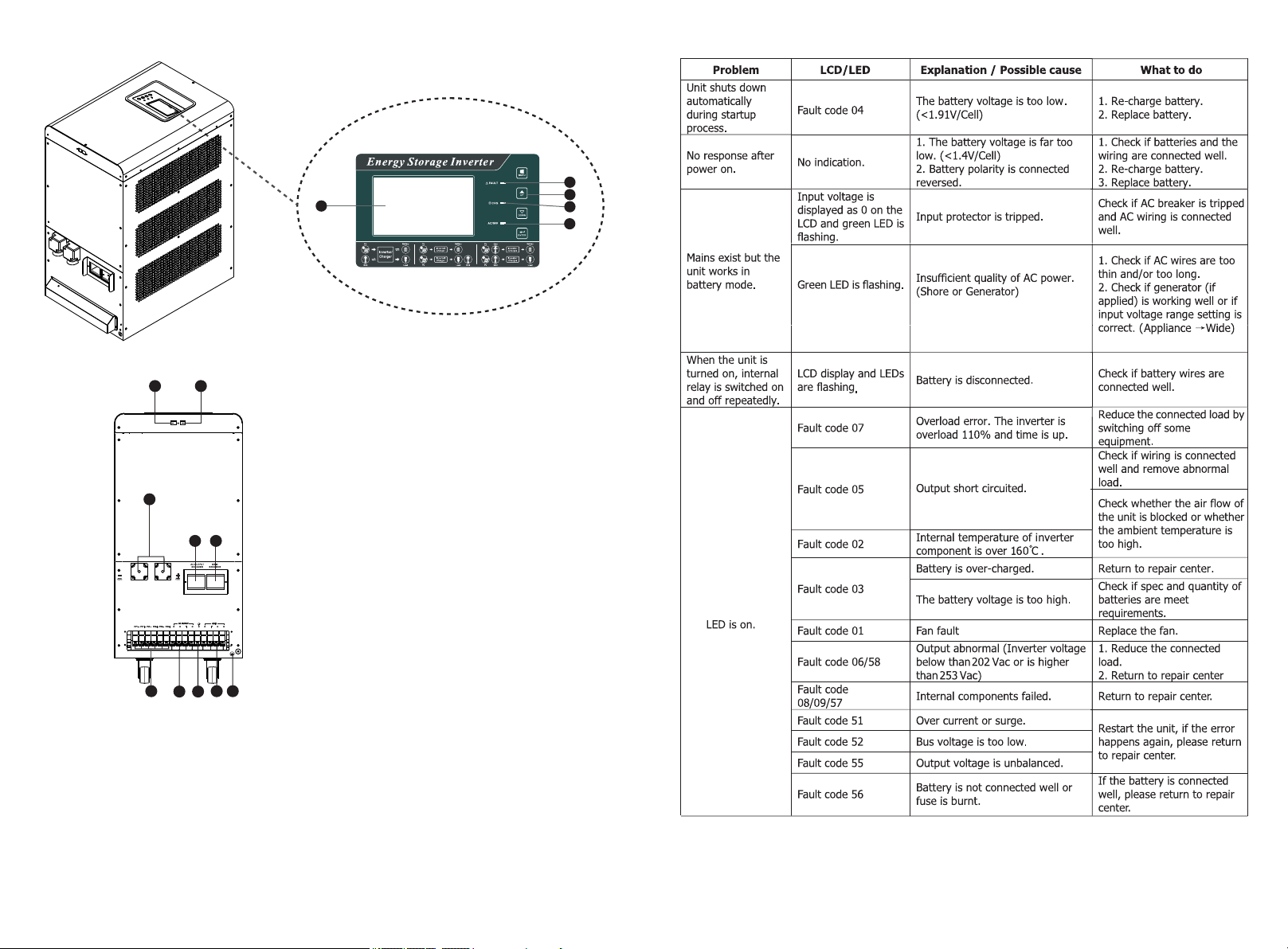
Product Overview
12 13
10
9
11 6
7814
TROUBLE SHOOTING
4
1
1. LCD display
2. S ta tu s in di ca to r
3. C ha rg in g in di ca to r
4. Fa ul t in di ca to r
5. F un ct io n bu tton s
6. G ri d br ea ker
7. AC Output
8. G ri d
9. P V in pu t
10 . Ba tt er y in pu t
11 . AC o ut pu t br ea ker
12 . CA N & RS 48 5 co mm un ic at io n po rt
13 . BTS
14
14. Grounding
5
3
2
Red
Packing List
Be fo re ins ta ll at io n, p le as e in sp ec t th e un it, Be sure that nothing inside the package is
da ma ge d. Yo u sh ou ld h av e re ce ived the following i te ms i ns id e of p ac ka ge :
The unit x 1 User manual x1
Soft ware CD x1 BT S ca bl e x1
Communic at io n ca bl e(RJ 45 t o DB 9) x 1
AC cable x2 (o nl y for single-p ha se u ni t)
Communic at io n ca bl e(US B to R S4 85 ) x1 ( Optional)
- 3 -
- 3 2 -
 Loading...