


1
Operating Instructions
Heating Press for Melting Splices
HPD 400 P 180
HPD 600 P 180
Müssel Maschinenbau GmbH
Reichelsweiherstraße 8
95615 Marktredwitz
GERMANY
Tel.: +49 9231 9980-0
Fax: +49 9231 9980-80
E-Mail: kontakt@muessel.com
Operating instruction: H002 / 0938 / 0940 Edition: 01/2016 Subject to alterations.

2
Introduction
We would like to congratulate you for having purchased the Müssel-Belting Tools made by Müssel
Maschinenbau GmbH and to thank you for the confidence you placed in us.
This operating instruction provides you with important information for the proper and safe use of the heating
press, HPD 400 P 180, HPD 600 P 180.
Owing to our experience over decades in the development and the fabrication of finishing tools for conveyor
belts and driving belts, these devices have been designed according to the latest state of technique and in
compliance with this application
in the detailed splicing instructions or in the belt specific technical data sheets of the belt manufacturer.
Please note that the future usage conditions of the conveyor belt have to be considered for the choice and
the finishing of splices.
The reproduction, distribution and utilization of this document as well as the communication of its contents
to others without express authorization is prohibited as far as this is not explicitly allowed by Müssel
Maschinenbau GmbH. Offenders will be held liable for the payment of damages. All rights reserved.
Any liability for errors and printing errors is excluded.
.
Please find further information on splicing types and finishing parameters
Operating instruction: H002 / 0938 / 0940 Edition: 01/2016 Subject to alterations.

3
Contents
1 General information
1.1 Name and address of the manufacturer
1.2 Identification of the device
1.3 CE-Declaration
1.4 Conformity
2 General safety instructions
2.1 Usage in accordance with regulations
2.2 Organisational measures
2.3 Personnel selection and qualification
2.4 Safety instructions for specific operating phases
2.5 Mobile devices
2.6 Safety instructions
3 Product description
3.1 Components and proper usage
3.2 How it works
3.3 Technical data
3.4 Wiring diagram
3.5 Accessories
4 Preparing the product for usage
4.1 Transport
4.2 Position
4.3 Electric installations
4.4 Utilities
4.5 Connection points for the compressed air
4.6 Control and limitation of temperature
5 Handling
5.1 General
5.2 Inserting the belt into the heating press
5.3 Closing the heating press
5.4 Connecting the water cooling system
5.5 Connecting the heating press to the mains and heating the splice
5.6 Cooling the splice
5.7 Removing the belt from the heating press
6 Controlling and cooling the heating press
6.1 Without control unit
6.2 With control unit
6.3 Using compressed air
7 Maintenance work
7.1 Spare parts
7.2 Wear parts
8 Disassembling and disposal
Operating instruction: H002 / 0938 / 0940 Edition: 01/2016 Subject to alterations.

4
Operating instruction: H002 / 0938 / 0940 Edition: 01/2016 Subject to alterations.

5
1 General information
1.1 Name and address of the manufacturer
Müssel Maschinenbau GmbH
Reichelsweiherstraße 8
95615 Marktredwitz
GERMANY
1.2 Identification of the device
Product designation: Heating press for melting splices
Serial/Type designation: HPD 400 P 180, HPD 600 P 180
Serial number: see type label
Year of construction: see type label
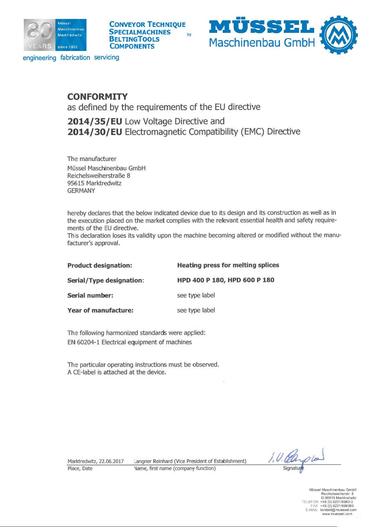
1.3 CE-Declaration
see fixed label
Operating instruction: H002 / 0938 / 0940 Edition: 01/2016 Subject to alterations.
6
1.4 Conformity
Operating instruction: H002 / 0938 / 0940 Edition: 01/2016 Subject to alterations.

7
2 General safety instructions
The following document contains important information on serious risks when operating the tool described or important technical information on the tool or processes used. Symbols are used to highlight this important information and indicate as follows:
This symbol is always to be found in connection with an endangerment and its respective
signal word.
Signal words hierarchy:
Danger: This signal word is indicating a person endangerment with a high risk level which
causes death or serious injury, in case it cannot be avoided.
Warning: This signal word is indicating a person endangerment with a medium risk level, which
can cause death or serious injury, in case it cannot be avoided.
Caution: This signal word is indicating an endangerment with a low risk level which can cause a
minor or moderate injury, in case it cannot be avoided.
Attention: This signal word is indicating a warning of material and environmental damages.
2.1 Usage in accordance with regulations
This device has been built as state of the art and according to the fundamental health and safety requirement of the EC machinery directive. However, its usage may result in risks to the body or life of
users or third parties, or adverse effects to devices and other property.
The device may only be used in proper technical condition as intended, in a safety- and hazard conscious manner and observing the operating instructions!
Observing the operating instructions and adhering to the inspection and maintenance conditions are
also parts of the intended use.
2.2 Organisational measures
The operating instructions must always be at hand at the place of use of the device!
In addition to the operating instructions, observe and instruct the user in all other generally applica-
ble legal and other mandatory regulations relevant to accident prevention and environmental protection!
The operating instructions must be supplemented by instructions covering the duties involved in supervising and notifying special organizational features, such as job organization, working sequences
or the personnel entrusted with the work.
Please only assign trained personnel familiar with the operating instructions of the device.
Check at regular intervals whether the personnel are carrying out the work in compliance with the
operating instructions and paying attention to risks and safety factors!
In order to minimize the risk of injury, garments must be close-fitting. Furthermore long hair must
be tied back and jewellery -including rings- have to be removed before beginning work.
Observe all safety instructions and warnings attached to the device and see to it that they are al-
ways complete and perfectly legible!
If the operating behaviour changes immediately stop the device and report the error to the respon-
sible department/person!
Operating instruction: H002 / 0938 / 0940 Edition: 01/2016 Subject to alterations.

8
Never make any modifications, additions or conversions which might affect safety without the supplier´s approval.
Additional mountings or modifications have as consequence that the responsibility for the accordance with the EU-directive has to be assured by the person who carries out the mountings and the
modifications.
Spare parts, only from the original equipment, comply with the technical requirements specified by
the manufacturer and guarantee the failure-free operation of the device.
2.3 Personnel selection and qualification
The device can only be operated by staff accordingly skilled and instructed.
Work on electrical equipment of the device must be performed by a qualified electrician or trained
individuals under the direction and supervision of an electrician according to electro-technical regulations.
2.4 Safety instructions for specific operating phases
The device can only be operated in a safe and absolutely reliable state. Make sure in particular that
all protective and safety-oriented devices are in place and fully functional.
Loosened screws and hose connections must be tightened upon completion of the maintenance and
repair work.
2.5 Mobile devices
In case of minor changes of place, please even disconnect the device from any external power supply! Properly reconnect to the mains prior to restarting the device!
Always use hoisting and slinging equipment with sufficient weight bearing capacity for loading!
Position hoisting devices or slinging means only on the load lifting appliances of the device that are
provided for this purpose!
Please take the necessary and appropriate measures for making sure that during the transportation
no device part may fall in or loosen!
2.6 Safety instructions
The removing of covers or parts of safety-oriented components may increase the risk of accident.
Conversions, maintenance and repair work must be performed by trained, competent and skilled
persons.
Always use original fuses with the required rating! If errors of the device electrical power supply occur immediately shut off the conveyor system!
Because of the risk of burns, make sure the device is always freely accessible and is not covered.
The devices do not have their own protection appliances against electrical overload. For this reason,
the operator must ensure that the electrical installations at the operated place, are protected from
overload.
Regularly inspect/check the electrical equipment of a device. Visible faults, such as loose connections, must be immediately rectified.
Operating instruction: H002 / 0938 / 0940 Edition: 01/2016 Subject to alterations.

9
Functional group
Components
Top part
Pressure beam
Pressure hose
Heating plate with edge cooling bar
Plug-in contact / cable
Bottom part
Pressure beam
Heating plate with edge cooling bar
Plug-in contact / cable
Eye bolts with nuts
Pneumatical hold-down bars (bottom hold-down bar without pressure hose / top hold-down bar with
pressure hose)
3 Product description
3.1 Components and proper usage
Heating presses are electrical heating devices for use in fabricating (splicing) belting material that
can withstand maximum temperatures of 200°C. Heating presses are used to splice belting material
using pressure and temperature. Depending on the requirement we differentiate between different
designs and type.
The heating press consists of the following components and functional groups:
3.2 How it works
In the closed heating press pressure and temperature are generated between the top and bottom
part and the electrically heated heating plates when compressed air is supplied; this caused the
melting of the inserted belting material as well as the splicing after a prescribed period (hold-downtime). Once cooled down, the finished splice has got the physical features required.
For further information on how the heating press functions, see chapter "5 Handling".
Operating instruction: H002 / 0938 / 0940 Edition: 01/2016 Subject to alterations.

10
HPD 400 P 180
HPD 600 P 180
Belt width max. (at 90°)
mm
400
600
Belt width max. (at 80°)
mm
350
550
Belt width max. (at 60°)
mm
230
430
Belt length min.
mm
1000
1000
Splice max.
mm
Z-110 and Z-Stepped
Z-110 and Z-Stepped
Heating plates length
mm
180
180
Length
mm
440
440
Width
mm
600
825
Height
mm
320
320
Weight (net)
kg
55,0
75,0
Voltage V 110 / 230
110 / 230
Capacity W 2x 1000
2x 1350
Heating up time up to 180°C
min
approx. 18
approx. 18
Cooling down time
from 180°C up to 40°C
min
approx. 2
approx. 2
Coolant water
water
Air pressure max.
bar
7
7
Heating temperature max.
°C
200
200
Material number
Designation
720101
HPD 400 P 180 (230V)
720102
HPD 400 P 180 (110V)
720103
HPD 600 P 180 (230V)
720104
HPD 600 P 180 (110V)
3.3 Technical data
Operating instruction: H002 / 0938 / 0940 Edition: 01/2016 Subject to alterations.

11
3.4 Wiring diagram
Valid for top and bottom part of plug-in connection cables.
Voltage: 230V / 110V
Valid for top and bottom part of fixed connection cables.
Voltage: 230V / 110V
Operating instruction: H002 / 0938 / 0940 Edition: 01/2016 Subject to alterations.

12
HPD 400 P 180
HPD 600 P 180
Designation
Optional with control unit:
7875134
HPS2 control unit (single phase)
7875122
CWD 55 E cooling device for HPS2
Note:
Should the heating presses be operated with a control unit of other manufacturers,
some problems may occur for which we cannot be made liable!
Optional without control unit:
7875126
Input inlet (230V), 16A, 2m
7875180
Input inlet US 110V, 15A, 2m
7870356
CWD 55 E cooling device
7871563
Digital measuring device
7871564
Temperature sensor standard
General:
730081
Compressor 230V, 6 l, portable
7871524
Compressor230V, 24 l, mobile
7870174
Separating paper 50 m x 330 mm
7872172
Textured fabric Standard, width 330 mm
(yard goods) Minimum quantity: 5 m
7870211
Soft pad 1 mm, width 330 mm
(yard goods) Minimum quantity: 5 m
7873029
Silicone fabric no. 1, width 330 mm
(yard goods) Minimum quantity: 5 m
Silicone embossing mats on request!
3.5 Accessories
Accessories are not included in the scope of delivery and must be ordered separately!
Operating instruction: H002 / 0938 / 0940 Edition: 01/2016 Subject to alterations.

13
4 Preparing the product for usage
Before starting the operation of the tool, the following steps must be carried out each time to ensure
that the tool works properly. Check the following points:
4.1 Transport
The transport / the relocation / the use of the device should be carried out by an appropriate lifting
appliance (regarding the minimum lifting force, please look at chapter “3.3 Technical data“). Prior to
this relocation, the device should be disconnected from the energy supply (electrical current and
compressed air).
The tool may only be transported in cooled-down condition and under observation of the generally
valid safety regulations.
Note:
When transporting, make sure that the heating presses are only transported or stored when they are
closed (This protects the heating surfaces best from damage). The filling of the pressure hose (0,5
bar is sufficient) avoids any unintentional opening of the press during the transport.
Warning
Make sure that the heating press is firmly locked in lifting.
In lifting and transporting the device, please handle particularly with care!
During the transport please do not keep staying under the floating load!
Lift the heating press only at the provided lifting points.
Attention
Do not lift the heating press at the hold-down bars!
Higher tilting danger owing to the irregular weight repartition!
4.2 Position
Heating presses and their components, in particular heating plates, must be only placed on surfaces
that can withstand maximum temperatures of 240°C. Otherwise damage can occur to materials that
are not heat resistant or they will present a fire risk. The surfaces must also be able to withstand the
static load from the weight of the heating presses.
Attention
Risk of burns! Make sure the heating press is always freely accessible and is not covered
up. Should the heating press be covered up, this will present a fire risk.
Operating instruction: H002 / 0938 / 0940 Edition: 01/2016 Subject to alterations.

14
4.3 Electric installations
The existing mains voltage must be suitable for the tools' operating voltage. The heating plates must
have their own electricity supply according to the information on the type plate.
The connection cables are delivered partial in plug-in form.
4.4 Utilities
Pressure equalizing metal sheets
Shim bars
Textured fabric standard
Silicone fabric no.1
Separating paper
Soft pad 1 mm
Thermometer
All utilities must be clean.
Operating instruction: H002 / 0938 / 0940 Edition: 01/2016 Subject to alterations.

15
Pressure hose
Hold-down bar
Hold-down bar
4.5 Connection points for the compressed air
The pressing power does not depend on the width of the inserted belt. The required pressing power
should not be exceed or below this value.
The Press is carefully to be closed.
Fill presses equipped with pressure hose only with cleaned and dry compressed air.
Fill pressure hose only, when the press is firmly closed and the hose is properly fitting.
Fill the pressure hose only by means of filling devices provided for this purpose; this makes also possible the later emptying.
Air pressure – pressure hose: max. 7 bar
Air pressure – hold-down bars: max. 4 bar
The function in-feed of compressed air is not controlled automatically and must be done from a stationary compressed air network or a compressor system. The maximum press inlet pressure is not
displayed or monitored on the heating press.
Caution
Risk of injury! Connect the pressure hoses carefully!
Check that compressed air connections work and do not leak.
Operating instruction: H002 / 0938 / 0940 Edition: 01/2016 Subject to alterations.

16
4.6 Control and limitation of temperature
Several parts of the heating device get extremely hot during operation; therefore touch the press
only at the points intended for.
The temperature must be measured always at the bore of the heating plate.
Other measuring points would falsify the reading.
Only gauged and operative measuring devices may be used!
Attention
The temperature of the heating plates may not exceed 200°C!
In case this temperature is exceeded, the temperature safety fuse would be destroyed
that is built-in for protecting the heating elements. The current supply is then interrupted.
Operating instruction: H002 / 0938 / 0940 Edition: 01/2016 Subject to alterations.

17
5 Handling
5.1 General
Heating presses are electrical heating devices for use in fabricating (splicing) belting material that
can withstand maximum temperatures of 200°C.
There are two basic methods of controlling the heating procedure,
a.) An automatic one using a control unit that carries out the heating and cooling phases on special
heating presses automatically after the operator has programmed in and
b.) A manual one where the operator supervises and carries out independently all the cycles.
Note:
When making melting splices always observe the splicing instructions for the belt type to be spliced.
5.2 Inserting the belt into the heating press
1. Prepare the two belt ends according to the required connection (Z-splice, wedged splice etc.).
2. Place the pressure equalizing metal sheet on the bottom part of the press and cover them by
silicone fabric No. 1.
3. The both belt ends must be centrically placed on the pressure equalizing metal sheet (with the
operating side reversed).
4. Place the shim bars (or material of the same thickness) to the left and right next to the ends of
the belt (refer to the following figure).
Note:
Always fold out the areas to be pressed to the full width. If the belting
material is a) narrower than the area to be pressed, (so that the press
do not flexing) extra pieces in the same thickness or several shim bars
of the corresponding width must also be inserted
5. Please entirely push together and mark the Z-splice (Fig. 1).
6. Place the top hold-down bar and tighten it slightly.
7. Centre and align the belt (Fig. 2), adjust the distance between the
two belt ends according to the instructions for the respective belt type
(belts mostly about 5 mm).
8. Fill up the pneumatically hold-down bar with compressed air.
Maximum 4 bars compressed air.
Operating instruction: H002 / 0938 / 0940 Edition: 01/2016 Subject to alterations.

18
Nut
Centering bore
Centering pin
Eye bolt
9. If necessary etc., cover the splice with additional material (PVC-Z-foil,
PU-Z-foil) (Fig. 3).
10. Depending on the belt type, place the prescribed cover material (silicone embossing mat, separating paper, textured fabric fine etc.) (Fig.
4).
11. Cover the splice with the top pressure equalizing metal sheet.
12. Place the top heating plate.
13. Place the top pressure beam with pressure hose.
5.3 Closing the heating press
1. Slightly tighten nut by hand.
2. Only then fill the pressure hose with air.
(maximum 7 bar)
Note:
The feeding of compressed air is not automatically
controlled and must be done in form of a stationary
compressed air network or a compressor system.
A pressure display does not exist!
Warning
Risk of injury! The permitted maximum air pressure for generating the pressing force is 7
bars. If you exceed this maximum figure, the device can burst!
Operating instruction: H002 / 0938 / 0940 Edition: 01/2016 Subject to alterations.

19
Circle reverse control
Front side
Back side
Drain
Supply
Circle reverse control
5.4 Connecting the water cooling system
Warning
Risk of injury! Connect the cooling hoses carefully to the tool. Leaking water or steam
can be leading to burns.
1. Make sure no more water is in the cooling system.
2. Before heating connect the cooling hoses as shown in the following figure to the rapid couplings
on the heating plates.
Note:
Only let in cooling water after the heating procedure has been completed. Only use clean water!
Only use original hoses with temperature resistance for cooling!
The temperature of the steam is 170°C and the pressure is 6 bar.
Check the connection between connector and hose.
Operating instruction: H002 / 0938 / 0940 Edition: 01/2016 Subject to alterations.

20
5.5 Connecting the heating press to the mains and heating the splice
1. Connect the heating press to the mains.
Attention
Risk of fire or damage because of overload to the electricity supply. The electricity supply
for the heating plate must be separated from the mains according to the indications mentioned on the type plate! If necessary, make sure the heating press has a separate electricity supply.
2. Observe the heating temperature using the thermometer included and put it in the measurement drill holes provided.
3. As soon as the heating temperature required has been reached, disconnect the heating press
from the mains by pulling out the plug on the heating plates. The data sheet for the belt provides information on the heating temperature and hold-down time.
Make sure the heating plates are not heated above 200°C as this will destroy the in-built melt fuse
or the heating resistance. You can automatically regulate the temperature using a control unit.
Warning
Risk of injury from burns. The heating plates can get very hot during heating (up to
200°C) Touching them without any protection will mean burns.
5.6 Cooling the splice
1. Only let in cooling water after the heating procedure has been completed. Only use clean water.
2. Cool the heating press till the heating plates has reached a temperature of approx. 40°C.
5.7 Removing the belt from the heating press
1. Please empty the pressure hose.
Note:
Empty the pressure hose only after the heating press has cooled down!
2. Please open the heating press and take off the belt.
3. If necessary, clean the edges and the surface of the belt from excess material.
The belt is prepared.
4. After use, clean the heating press.
Operating instruction: H002 / 0938 / 0940 Edition: 01/2016 Subject to alterations.

21
6 Controlling and cooling the heating press
6.1 Without control unit
The heating device can be operated without using a control unit.
The temperature can be supervised by watching the insert thermometer. When the necessary temperature is reached, the heating press is separated from the mains.
The supply in cooling water can be done by means of a hose and is hand-operated. The backpressure valve must be closed after the device has cooled down. Please connect the sewage hose
Please blow out the remaining cooling water with compressed air.
6.2 With control unit (recommended by the manufacturer)
Note:
Should the heating presses be operated with a control unit of other manufacturers, some problems
may occur for which we are not made liable!
A control unit automates the procedure of heating, controlling time and cooling of the heating presses.
The temperature of the upper and lower heating plate is measured by means of a temperature
probe and the signal is transferred to the temperature regulators.
The temperature controller indicate the target temperature and set-point temperature of the heating
plates.
The temperature controllers indicate the reached temperature and switch off the mains as soon as
the adjusted temperature and the required control response time have been reached.
Then the cooling water supply is switched on, and switched off as soon as the adjusted cooling temperature has been reached.
The cooling water is pumped into the circulation by means of a submerged pump from a portable
coolant reservoir.
Note:
Cooling water residues are not automatically blowing out.
Should the water in the coolant reservoir be heated in such a way that the adjusted cooling temperature cannot be reached, the water must be exchanged. This is only necessary for the larger
presses or several successive heating procedures. After this the heating procedure can be continued.
6.3 Using compressed air
The compressed-air supply is not automatically regulated, but is either done from the stationary
compressed-air system or a small compressor or a battery compressor.
Compressed air is used for pressure hoses and for the blowing out of the coolant passage required
in the heating plates.
Operating instruction: H002 / 0938 / 0940 Edition: 01/2016 Subject to alterations.

22
7 Maintenance work
Before operating the tool, the following maintenance work must be carried out each time to ensure
that the tool works properly. If damage is detected during maintenance that cannot be eliminated on
site, the tool must no longer be used and has to be sent for repair to the manufacturer.
Check the following each time before use:
Heating press for damage
Connectors and cable for damage
Water hoses and connections for tightness
Pressure hoses for tightness
Pressure equalizing metal sheet for smoothness and cleanliness
Heating plates for cleanliness
Shim bars for cleanliness
Drill holes for the thermometer for cleanliness
Screws for properly sit
Check after using several times:
Check heating plates for bowing
Test the heating plates for bowing in cold and in warm condition by means of a straight edge. If
the plates are bowing by more than 0,3 mm, the plates must be returned to our factory for
overhaul.
Condition of the press
To do this make one (or several) test splices.
Whether the side cooling bars jut out
For heating plates with cooling bars at the side, in a non-pressurised state the cooling bars
should jut out 2 mm over the area to be heated. Should the cooling bars jut out more than 2
mm, additional insulating material must be inserted into the heating plate.
Level o fair pressure (surface pressure)
The surface pressure the splice is heated under, does not depend on the width of the belt inserted. Maximum air pressure 7,0 bar. Close the heating press carefully.
Note:
Heating presses with pressure hoses, should be filled with clean and dry compressed air.
Only fill the pressure hose when the heating press has been tightly closed and the pressure
hose is lying flatly and snugly between the pressure beams and the heating plates.
Temperatures of different parts of the heating press
Always measure the temperature in the heating plates bore hole. Measurements on other
places will not produce correct results.
Warning
Risk of injury! The heating plates get very hot during the heating procedure, the operator risks burns.
Eye bolts, nuts and screws of the hold-down bars, lubricate as needed
Check every twelve months:
According to the VDE guideline 0701/0702 electrical tools must be checked once every twelve
months on site or according to local regulations in each country.
Operating instruction: H002 / 0938 / 0940 Edition: 01/2016 Subject to alterations.

23
HPD 400 P 180
HPD 600 P 180
Designation
7871422
7871422
Temperature fuse
787022520
787022520
Spring for cooling profile
7870511
7870511
Jack 3/8 inch RPL 08.1152
7870512
7870512
Hose coupling
7870513
7870513
Viton seal o-ring for hose coupling
7870804
7870805
Eye bolt
78710171
7871018
Plastic coated tension nut without collar
7870225142
7870225142
Pin rod ø 16 with thread M12
7870225143
7870226143
Link bold
7870232
7870233
Pressure hose complete with alu-plates
and pneumatic fittings
7872264
7872264
Pneumatic coupling ¼”
7870746
7870746
Plug for air connection suitable for pneumatic
coupling 1/4”
7872265
7872265
Hose connection consisting of: thread connection
piece, hexagon nut, disc, 2 pieces sealing (for
hose DN 75, 90)
7871053
on request
Pneumatical hold-down bar (1 set = 1x normal
1x laterally reversed)
787105321
787105321
Star knob screw M10 x 125 mm for hold-down
bar
7871346
7871346
Star knob M10
78710531
78710541
Pressure hose for hold-down bar complete with
clamps and pneumatic coupling
78707581
78707581
Hose connection for hold-down bar consisting of:
thread connection piece, hexagon nut, disc, 2
pieces sealing (for hose DN 25)
78707582
78707582
Hexagon bush 1/8 made of brass for hose connector (DN 25)
78710533
78710533
Steel-angle for hold-down bar
78710534
78710534
Adapter plate for fixing the hold-down bar on the
bottom heating packet
7870785
7870785
Cooling hose DN 10 – 500 mm
7872786
7872786
Thermometer digital, w/100 mm staff
7870193
7870194
Pressure equalizing metal sheet
7870198
7870198
Shim bar set 20 x 450 mm
(0,2 – 3,0 mm thickness)
7.1 Spare parts
Operating instruction: H002 / 0938 / 0940 Edition: 01/2016 Subject to alterations.

24
HPD 400 P 180
HPD 600 P 180
Designation
7871393
7871395
Heating element 230V with temperature fuse
7871392
7871394
Heating element 110V with temperature fuse
7870615
7870616
Insulating insert with metal sheet,
material: mineral fibre
7875276
7875278
Insulating insert special (multi-layer setup) con-
sisting of: metal sheet, heat insulation plate, glas
fibre plate
7.2 Wear parts
Materials and parts that are enumerated in the technical instructions as wear parts are excluded
from the guarantee.
Operating instruction: H002 / 0938 / 0940 Edition: 01/2016 Subject to alterations.

25
8 Disassembling and disposal
The disassembling in individual components can only be effected by competent staff with a good
knowledge of machine building.
Please sort out the device according to the respective materials (metal, plastics, electronic) and recycle them.
Operating instruction: H002 / 0938 / 0940 Edition: 01/2016 Subject to alterations.
 Loading...