

Mussel AIR 1200 P Operating Instructions Manual
1
Operating Instructions
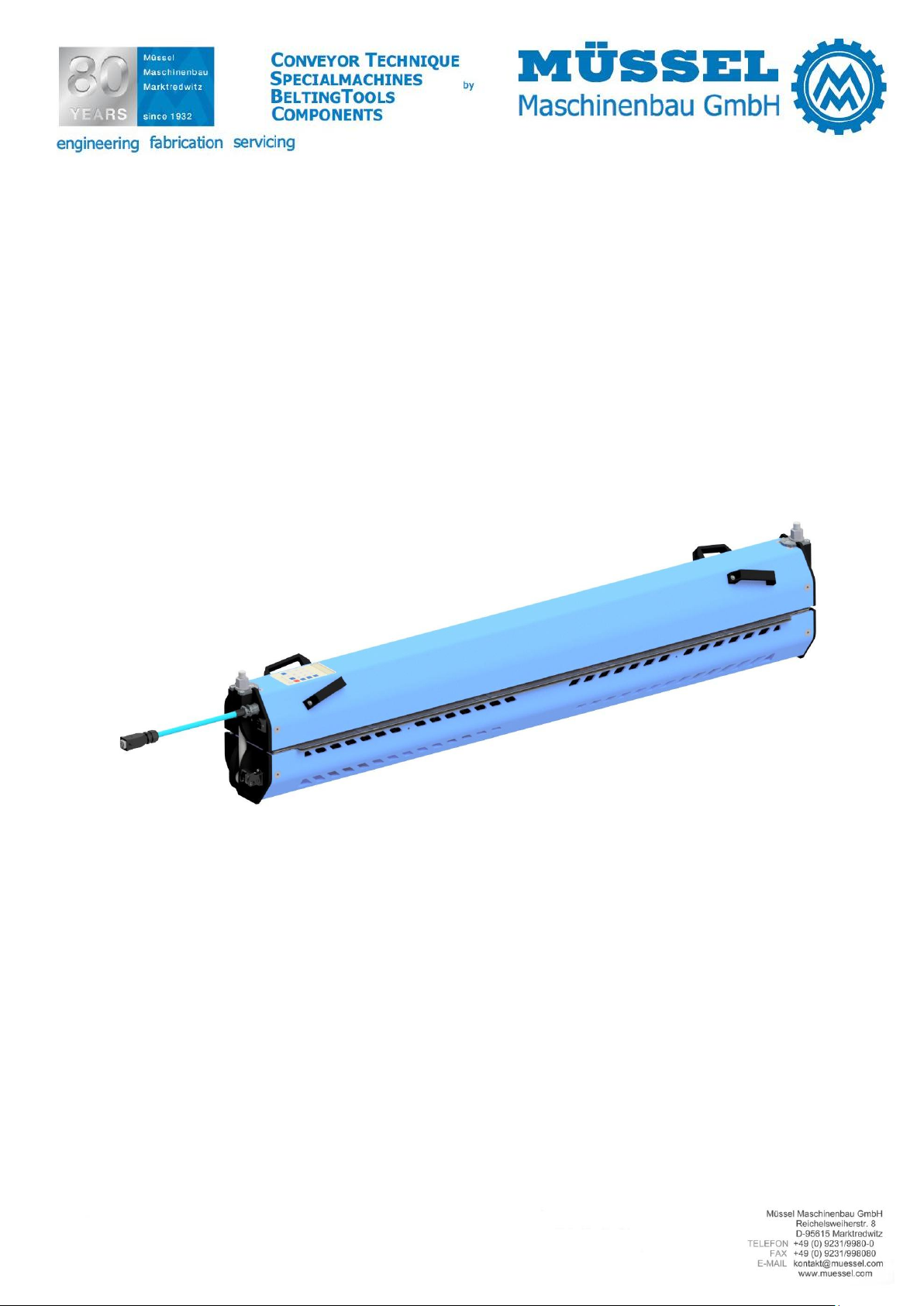
Air Cooled Heating Press
AIR 1200 P
Müssel Maschinenbau GmbH
Reichelsweiherstraße 8
95615 Marktredwitz
GERMANY
Tel.: +49 9231 9980-0
Fax: +49 9231 9980-80
E-Mail: kontakt@muessel.com
Operating instruction: O003 / 5759 Edition: 04/2019
Reproduction, duplication of this document - even a partial form –
are subject to our permission. All rights reserved.
In this data sheet any liability for changes, errors or misprints is excluded.

2
Introduction
We would like to congratulate you for having purchased the Müssel-Belting Tools made by Müssel
Maschinenbau GmbH and to thank you for the confidence you placed in us.
This operating instruction provides you with important information for the proper and safe use of the air
cooled heating press, AIR 1200 P.
Owing to our experience over decades in the development and the fabrication of finishing tools for conveyor
belts and driving belts, these devices have been designed according to the latest state of technique and in
compliance with this application
in the detailed splicing instructions or in the belt specific technical data sheets of the belt manufacturer.
Please note that the future usage conditions of the conveyor belt have to be considered for the choice and
the finishing of splices.
The reproduction, distribution and utilization of this document as well as the communication of its contents
to others without express authorization is prohibited as far as this is not explicitly allowed by Müssel
Maschinenbau GmbH. Offenders will be held liable for the payment of damages. All rights reserved.
Any liability for errors and printing errors is excluded.
.
Please find further information on splicing types and finishing parameters
Operating instruction: O003 / 5759 Edition: 04/2019
Reproduction, duplication of this document - even a partial form –
are subject to our permission. All rights reserved.
In this data sheet any liability for changes, errors or misprints is excluded.

3
Contents
1 General information
1.1 Name and address of the manufacturer
1.2 Identification of the device
1.3 CE-Declaration
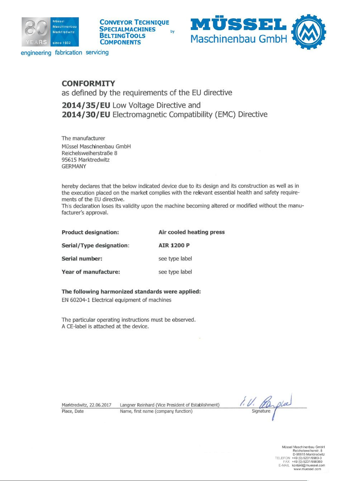
1.4 Conformity
2 General safety instructions
2.1 Usage in accordance with regulations
2.2 Organisational measures
2.3 Personnel selection and qualification
2.4 Safety instructions for specific operating phases
2.5 Mobile devices
2.6 Safety instructions
3 Product description
3.1 Components
3.2 How it works
3.3 Technical data
3.4 Wiring diagram
3.5 Accessories
4 Preparing the product for usage
4.1 Transport
4.2 Position
4.3 Electric installations
4.4 Utilities
4.5 Generation and control of pressure
4.6 Control and limitation of temperature
4.7 Air cooling system
5 Handling
5.1 General
5.2 Inserting the belt into the heating press
5.3 Closing the heating press
5.4 Connecting the heating press to the mains
5.5 Adjusting the temperature control unit and heating the splice
5.6 Cooling the splice
5.7 Removing the belt from the heating press
6 Configuration program
7 Maintenance work
7.1 Spare parts
7.2 Wear parts
8 Disassembling and disposal
9 Error notes
Operating instruction: O003 / 5759 Edition: 04/2019
Reproduction, duplication of this document - even a partial form –
are subject to our permission. All rights reserved.
In this data sheet any liability for changes, errors or misprints is excluded.

4
Operating instruction: O003 / 5759 Edition: 04/2019
Reproduction, duplication of this document - even a partial form –
are subject to our permission. All rights reserved.
In this data sheet any liability for changes, errors or misprints is excluded.

5
1 General information
1.1 Name and address of the manufacturer
Müssel Maschinenbau GmbH
Reichelsweiherstraße 8
95615 Marktredwitz
GERMANY
1.2 Identification of the device
Product designation: Air cooled heating press
Serial/Type designation: AIR 1200 P
Serial number: see type label
Year of construction: see type label
1.3 CE-Declaration
see fixed label
Operating instruction: O003 / 5759 Edition: 04/2019
Reproduction, duplication of this document - even a partial form –
are subject to our permission. All rights reserved.
In this data sheet any liability for changes, errors or misprints is excluded.
6
1.4 Conformity
Operating instruction: O003 / 5759 Edition: 04/2019
Reproduction, duplication of this document - even a partial form –
are subject to our permission. All rights reserved.
In this data sheet any liability for changes, errors or misprints is excluded.

7
2 General safety instructions
The following document contains important information on serious risks when operating the tool described or important technical information on the tool or processes used. Symbols are used to highlight this important information and indicate as follows:
This symbol is always to be found in connection with an endangerment and its respective
signal word.
Signal words hierarchy:
Danger: This signal word is indicating a person endangerment with a high risk level which
causes death or serious injury, in case it cannot be avoided.
Warning: This signal word is indicating a person endangerment with a medium risk level, which
can cause death or serious injury, in case it cannot be avoided.
Caution: This signal word is indicating an endangerment with a low risk level which can cause a
minor or moderate injury, in case it cannot be avoided.
Attention: This signal word is indicating a warning of material and environmental damages.
2.1 Usage in accordance with regulations
This device has been built as state of the art and according to the fundamental health and safety requirement of the EC machinery directive. However, its usage may result in risks to the body or life of
users or third parties, or adverse effects to devices and other property.
The device may only be used in proper technical condition as intended, in a safety- and hazard conscious manner and observing the operating instructions!
Observing the operating instructions and adhering to the inspection and maintenance conditions are
also parts of the intended use.
2.2 Organisational measures
The operating instructions must always be at hand at the place of use of the device!
In addition to the operating instructions, observe and instruct the user in all other generally applica-
ble legal and other mandatory regulations relevant to accident prevention and environmental protection!
The operating instructions must be supplemented by instructions covering the duties involved in supervising and notifying special organizational features, such as job organization, working sequences
or the personnel entrusted with the work.
Please only assign trained personnel familiar with the operating instructions on the device.
Check at regular intervals whether the personnel are carrying out the work in compliance with the
operating instructions and paying attention to risks and safety factors!
In order to minimize the risk of injury, garments must be close-fitting. Furthermore long hair must
be tied back and jewellery -including rings- have to be removed before beginning work.
Observe all safety instructions and warnings attached to the device and see to it that they are al-
ways complete and perfectly legible!
If the operating behaviour changes, immediately stop the device and report the error to the respon-
sible department/person!
Operating instruction: O003 / 5759 Edition: 04/2019
Reproduction, duplication of this document - even a partial form –
are subject to our permission. All rights reserved.
In this data sheet any liability for changes, errors or misprints is excluded.

8
Never make any modifications, additions or conversions which might affect safety without the supplier´s approval.
Additional mountings or modifications have as consequence that the responsibility for the accordance with the EU-directive has to be assured by the person who carries out the mountings and the
modifications.
Spare parts, only, from the original equipment comply with the technical requirements specified by
the manufacturer and guarantee the failure-free operation of the device.
2.3 Personnel selection and qualification
The device can only be operated by staff accordingly skilled and instructed.
Work on electrical equipment of the device must be performed by a qualified electrician or trained
individuals under the direction and supervision of an electrician according to electro-technical regulations.
2.4 Safety instructions for specific operating phases
The device can only be operated in a safe and absolutely reliable state. Make sure in particular that
all protective and safety-oriented devices are in place and fully functional.
Loosened screws and hose connections must be tightened upon completion of the maintenance and
repair work.
2.5 Mobile devices
In case of minor changes of place, please even disconnect the device from any external power supply! Properly reconnect to the mains prior to restarting the device!
Always use hoisting and slinging equipment with sufficient weight bearing capacity for loading!
Position hoisting devices or slinging means only on the load lifting appliances of the device that are
provided for this purpose!
Please take the necessary and appropriate measures for making sure that during the transportation
no device part may fall in or loosen!
2.6 Safety instructions
The removing of covers or parts of safety-oriented components may increase the risk of accident.
Conversions, maintenance and repair work must be performed by trained, competent and skilled
persons.
Because of the risk of burns, make sure the device is always freely accessible and is not covered.
The devices do not have their own protection appliances against electrical overload. For this reason,
the operator must ensure that the electrical installations at the operated place, are protected from
overload.
Regularly inspect/check the electrical equipment of a device. Visible faults, such as loose connections
must be immediately rectified.
Operating instruction: O003 / 5759 Edition: 04/2019
Reproduction, duplication of this document - even a partial form –
are subject to our permission. All rights reserved.
In this data sheet any liability for changes, errors or misprints is excluded.
9
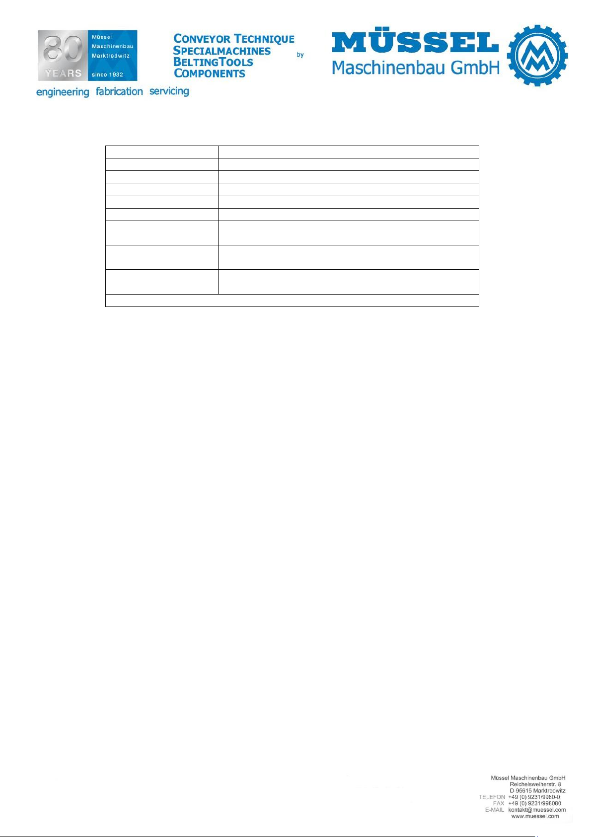
Functional group
Components
Top part
Pressure beam
Pressure hose
Heating plate
USB-contact
Temperature control unit
Compressor
Compressed air regulator with
display
Handles
Connecting cable of the heating
plates
Plug-in contact
Bottom part
Pressure beam
Heating plate
Ventilators for cooling
Eye bolt with collar nut
Plug-in contact for connecting
cable
Mechanical hold-down bars (not
included in the scope of delivery)
3 Product description
3.1 Components
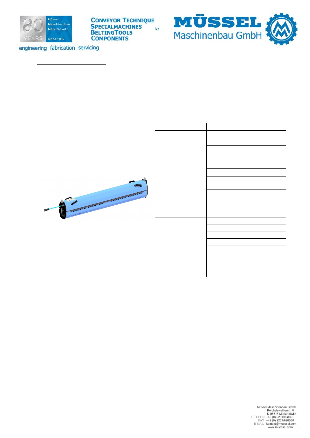
Heating presses are electrical heating devices for use in fabricating (splicing) belting material that
can withstand maximum temperatures of 210°C. Heating presses are used to splice endlessly belting
material using pressure and temperature. Depending on the requirement we differentiate between
different designs and types.
The heating press consists of the following components and functional groups:
3.2 How it works
In the closed heating press pressure and temperature are generated between the top and bottom
part and the electrically heated heating plates in supplying compressed air; this causes the melting
of the inserted belting material as well as the splicing after a prescribed period (heating-up time and
hold-down-time). Once cooled down, the finished splice has got the physical features required.
For further information on how the heating press functions, see chapter "5 Handling".
Operating instruction: O003 / 5759 Edition: 04/2019
Reproduction, duplication of this document - even a partial form –
are subject to our permission. All rights reserved.
In this data sheet any liability for changes, errors or misprints is excluded.

10
Belt width max. (at 90°)
mm
1200
Belt width max. (at 80°)
mm
1115
Belt width max. (at 60°)
mm
940
Default belt width min.
(at 90°)
mm
900
Belt length min.
without hold-down bar
mm
580
Belt length min.
with hold-down bar
mm
800
Max. splice length
mm
90
Heating plates length
mm
200
Length
mm
200
Length with hold-down bar
mm
330
Complete width
mm
1450
Complete height
mm
265
Weight (net)
kg
approx. 52,0
Complete weight with holddown bar
kg
55,0
Voltage
V
230
Capacity W 2x 1620
Heating up time up to 170°C
min
approx. 5
Cooling down time
from 170°C up to 40°C
min
approx. 19
Coolant
Air
Air pressure factory setting
bar
2
Air pressure max.
bar
2,5
Time for pressure generation
min
5:30
Heating temperature max.
°C
210
Ventilator
pcs 4 Material number
Designation
720477
AIR 1200 P (230V)
3.3 Technical data
Operating instruction: O003 / 5759 Edition: 04/2019
Reproduction, duplication of this document - even a partial form –
are subject to our permission. All rights reserved.
In this data sheet any liability for changes, errors or misprints is excluded.
11
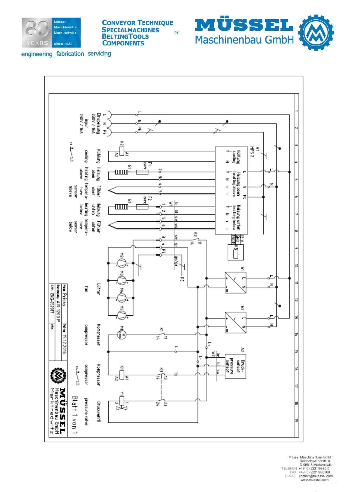
3.4 Wiring diagram
Operating instruction: O003 / 5759 Edition: 04/2019
Reproduction, duplication of this document - even a partial form –
are subject to our permission. All rights reserved.
In this data sheet any liability for changes, errors or misprints is excluded.
12
Material number
Designation
720478
Hold-down bar
730088
Handling case
7870174
Separating paper glossy 50 m x 330 mm
7870620
Separating paper matt 50 m x 400 mm
7872163
Separating paper VEZ 50 m x 330 mm
7872171
Textured fabric Standard, width 220 mm (yard goods)
Minimum quantity: 5 m
7872185
Soft pad 1 mm, width 220 mm (yard goods)
Minimum quantity: 5 m
7872192
Silicone fabric no. 1, width 220 mm (yard goods)
Minimum quantity: 5 m
Silicone embossing mats on request!
3.5 Accessories
Accessories are not included in the scope of delivery and must be ordered separately!
Operating instruction: O003 / 5759 Edition: 04/2019
Reproduction, duplication of this document - even a partial form –
are subject to our permission. All rights reserved.
In this data sheet any liability for changes, errors or misprints is excluded.
13
4 Preparing the product for usage
Before starting the operation of the tool, the following steps must be carried out each time to ensure
that the tool works properly. Check the following points:
4.1 Transport
The transport / the relocation / the use of the device should be carried out by an appropriate lifting
appliance (regarding the minimum lifting force, please look at chapter “3.3 Technical data“). Prior to
this relocation, the device should be disconnected from the energy supply (electrical current).
The tool may only be transported in cooled-down condition and under observation of the generally
valid safety regulations.
Note:
When transporting, make sure that the heating presses are only transported or stored when they are
closed (This protects the heating surfaces best from damage).
Warning
Make sure that the heating press is firmly locked in lifting.
In lifting and transporting the device, please handle particularly with care!
During the transport please do not keep staying under the floating load!
Lift the heating press only at the provided lifting points „4 handles”.
Attention
Do not lift the heating press at the hold-down bars!
Higher tilting danger owing to the irregular weight repartition!
4.2 Position
Heating presses and their components, in particular heating plates, must be only placed on surfaces
that can withstand maximum warming temperatures of 240°C. Otherwise damage can occur to materials that are not heat resistant or they will present a fire risk. The surfaces must also be able to
withstand the static load from the weight of the heating presses.
Attention
Risk of burns! Make sure the heating press is always freely accessible and is not covered
up. Should the heating press be covered up, this will present a fire risk.
4.3 Electric installations
The existing mains voltage must be suitable for the tools' operating voltage.
The connection cables are delivered in plug-in form.
4.4 Utilities
Textured fabric standard
Silicone fabric no.1
Separating paper
Soft pad 1 mm
All utilities must be clean.
Operating instruction: O003 / 5759 Edition: 04/2019
Reproduction, duplication of this document - even a partial form –
are subject to our permission. All rights reserved.
In this data sheet any liability for changes, errors or misprints is excluded.
 Loading...