

Electric Fireplace
Holds up to a 55” flat panel television
Foyer Électrique
Le support de TV supportent un
télévision plat jusqu’à 55”
Chimenea Eléctrica
El soporte de Televisión sostiene hasta
un televisor de pantalla plana de 55“
W
A
R
E
T
E
11
R
A
N
T
L
À
E
I
U
S
N
YEAR
AN
AÑO
Y
A
M
A
I
S
O
N
P
R
O
P
I
A
C
A
S
A
M
O
H
N
I
N
A
R
A
G
A
Í
T
N
A
R
A
G
save These InsTrucTIons
conserver ces InsTrucTIons
guarde esTas InsTruccIones
MTVS2500SCH
Assembly Instructions
Instructions d’assemblage
Instrucciones de montaje
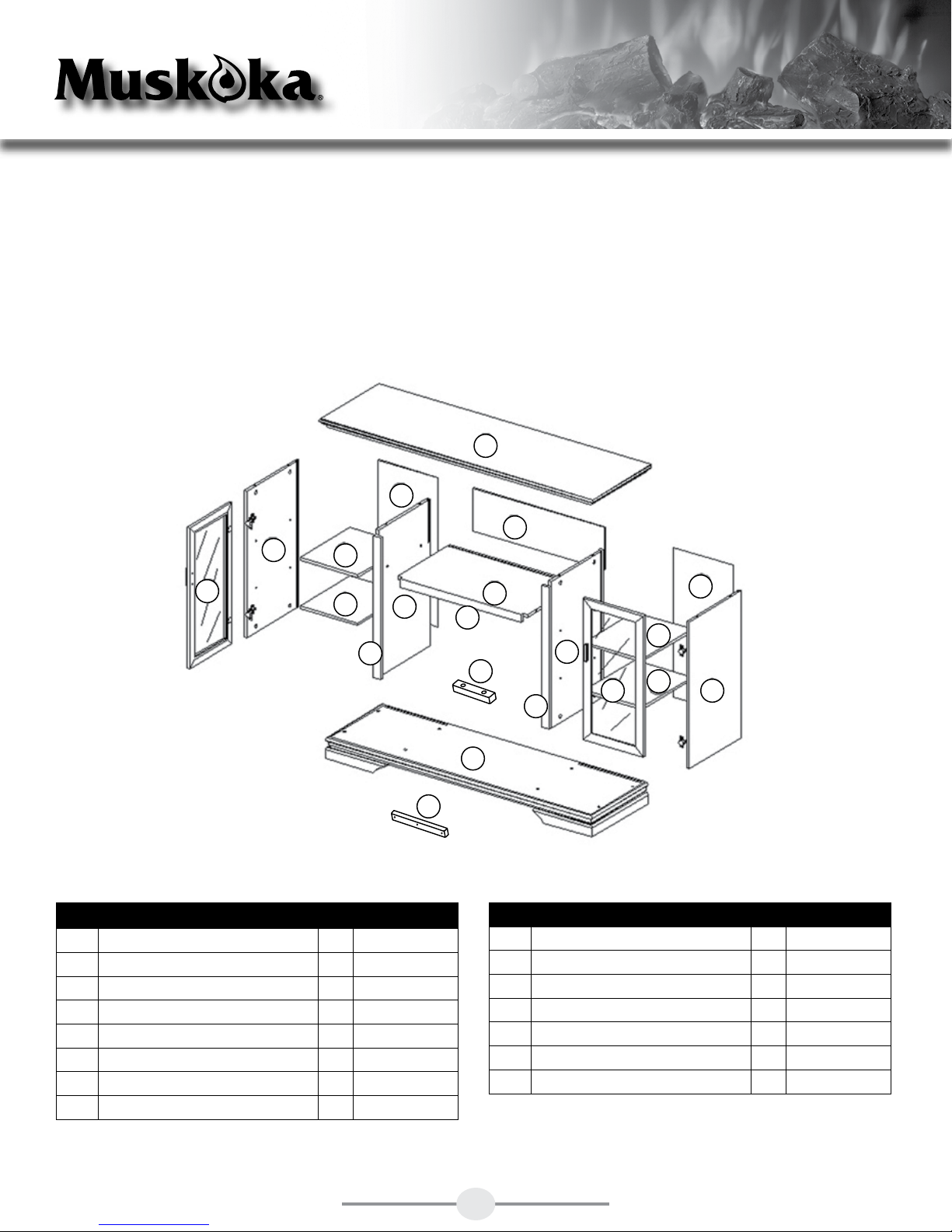
TIPS FOR THE ASSEMBLY OF YOUR NEW MANTEL
Before you begin assembly, locate the instructions and hardware. Take out all the parts and compare
them to the diagrams below. Be sure you have all the parts and can identify them.
A helping hand is always good. Assemble your mantel with an adult assistant if possible. Some pieces
are heavy and will need to be held by a helper. Assembly time will take approximately 30-60 minutes.
I
G
H
E
J
L
J
B
M
Part Description Qty. Part #
A Right Side Panel Interior 1
B Left Side Panel Interior 1
C Central Shelf 1
D Base 1
E Exterior Panel 2
F Central Shelf Trim Piece 1
G Back Panel 2
H Storage Back Panel 1
ZZ.2500SCH.01
ZZ.2500SCH.02
ZZ.2500SCH.03
ZZ.2500SCH.04
ZZ.2500SCH.05
ZZ.2500SCH.06
ZZ.2500SCH.07
ZZ.2500SCH.08
O
C
G
F
J
A
N
K
J
E
M
D
Part Description Qty. Part #
I Top 1
J Shelf 4
K Right Side Door 1
L Left Side Door 1
M Interior Panel Trim Piece 2
N Firebox Brace 1
O Base Support 1
ZZ.2500SCH.09
ZZ.2500SCH.10
ZZ.2500SCH.11
ZZ.2500SCH.12
ZZ.2500SCH.13
ZZ.2500SCH.14
ZZ.2500SCH.15
1

HARDWARE
AA BB CC DD EE
Cam Lock
Qty. 32
Plastic Cam
Cap
Mounting
Peg
Qty. 32
Qty. 16
Cam
Lock Dowel
Qty. 32
HH
II JJ KK LL
Small Screw
Qty. 19
FF
Handle
Qty. 2
MM
Nylon Strap
Qty. 1
NN
Door
Hinge
Mounting
Bracket
Qty. 2
Touch-Up
PP
Pen
Wall
Anchor
Qty. 1
Large
Screw
Qty. 1
Handle
Screw
Qty. 4
Back Panel
Screws
Qty. 44
Qty. 4
Qty. 1
2

GET READY TO START
Before assembly, use scissors to unwrap the parts from the packaging. DO NOT use a box cutter or
exacto-knife as you may cut into the mantel pieces inside the box and damage the finish. Check for the
hardware bag located inside the packaging, taped to the top box. Be sure you DO NOT discard any
pieces.
Step 1
Locate the central shelf trim piece (F). Insert 3 cam
lock dowels (AA) into the holes on the back of the
trim piece. The back side is the unfinished side.
Locate the central shelf (C). Make sure the central
shelf finished side is facing up with the mouse hole
at the back. Insert 3 cam locks (BB) into the holes
on the underside of the central shelf (C). Make
sure the arrows on the cam locks (BB) are pointing
AA
towards the trim piece. Line up the cam lock dowels
(AA) in the trim piece with the holes on the front
BB
edge of the central shelf (C). Push together the
trim piece (F) and the central shelf (C) until flush.
CC
Tighten cam locks (BB). Do not strip the cam locks
by overtightening them.
Place cam caps (CC) over the 3 cam locks.
Hardware Used
AA Cam Lock Dowels x 3
BB Cam Locks x 3
CC Cam Cap x 3
Step 2
Locate the left side panel interior trim piece (M).
Insert 3 cam lock dowels (AA) into the holes on
the back of the trim piece (M). The back side is the
unfinished side.
Locate the left side panel interior (B). Make sure
the left side panel interior (B) finished side is facing
out with the mouse hole at the bottom. Insert cam
locks (BB) into the holes on the right side of the left
side panel interior (B). Make sure the arrows on
the cam locks (BB) are pointing towards the trim
piece (M). Line up the cam lock dowels (AA) in the
trim piece (M) with the holes on the edge of the left
side panel interior (B). Push together the trim piece
(M) and the left side panel interior (B) until flush.
Tighten cam locks (BB). Do not strip the cam locks
by overtightening them.
Repeat for the right side panel interior (A).
AA
BB
CC
Hardware Used
AA Cam Lock Dowels x 6
BB Cam Locks x 6
CC Cam Cap x 6
Place cam caps (CC) over the 6 cam locks.
3

Step 3
Locate the base (D). Insert 3 cam lock dowels (AA)
into the holes under the base (D). Locate the base
support (O). Insert 3 cam locks (BB) into the holes
on the front of the base support (O). The backside
is the unfinished side. Make sure the arrows on the
cam locks (BB) are pointing up toward the base
(D). Push together the base support (O) and the
base (D) until flush. Tighten cam locks (BB). Do not
strip the cam locks (BB) by overtightening them.
Place cam caps (CC) over the 3 cam locks (BB).
Step 4
Locate the left side panel interior (B). Insert 2 cam
lock dowels (AA) into the holes on the inside of
the left side panel interior (B). Insert 2 cam locks
(AA) into the underside of the central shelf (C).
Make sure the arrows on the cam locks (BB) are
pointing towards the left side panel interior (B).
Push together the left side panel interior (B) and
the central shelf (C) until flush. Tighten cam locks
(BB). Do not strip the cam locks by overtightening
them.
AA
BB
CC
AA
Hardware Used
AA Cam Lock Dowels x 3
BB Cam Locks x 3
CC Cam Cap x 3
BB
CC
Repeat for the right side panel interior (A).
Place cam caps (CC) over the 4 cam locks (BB) on
the underside of the central shelf.
Hardware Used
AA Cam Lock Dowels x 4
BB Cam Locks x 4
CC Cam Cap x 4
4
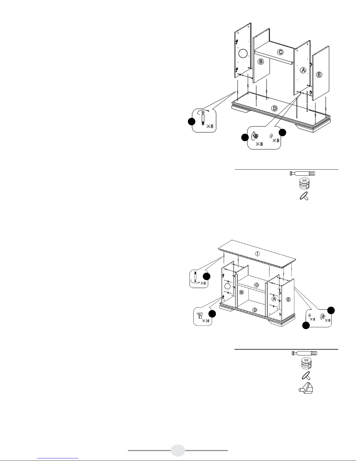
Step 5
Insert 8 cam lock dowels (AA) into the 8 holes
shown on the base (D). Insert 2 cam locks (BB)
into the bottom outside of each of the left and
right side panel interiors (B & A). Insert 2 cam
locks (BB) into the bottom inside of each of the left
and right side panel exteriors (E). Make sure the
cam lock arrows are pointing down toward the
base.
Push all 4 panels down onto the base (D) until
flush. Tighten cam locks (BB). Do not strip the cam
locks by overtightening them.
Place cam caps (CC) over the 8 cam locks (BB).
E
AA
CC
BB
Hardware Used
AA Cam Lock Dowels x 8
BB Cam Locks x 8
CC Cam Cap x 8
Step 6
Locate the top (I). Make sure the finished side
is up. Insert 8 cam lock dowels (AA) into the
holes on the underside of the top (I). Insert 2 cam
locks (BB) on the top inside of the left side panel
exterior (E) and the left side panel interior (B).
Repeat for the right side panel interior (A) and the
right side panel exterior (E). Make sure all cam
lock arrows are pointing upward toward the
top (I).
Make sure the cam lock dowels (AA) line up with
the holes on the top of the interior and exterior
panels (A, B & E). Push the top (I) down until flush.
Tighten cam locks (BB). Do not strip the cam locks
by overtightening them.
Insert 16 mounting pegs (DD) on the inside of the
left and right side storage areas.
AA
DD
E
BB
CC
Hardware Used
AA Cam Lock Dowels x 8
BB Cam Locks x 8
CC Cam Cap x 8
DD Mounting Pegs x 16
5

Step 7
Locate the 2 back panels (G) and the storage back
panel (H). Make sure the finished sides of the
panels face in toward the mantel. Line up a back
panel (G) so it is flush to the back of the left side
panel interior (B) and left side panel exterior (E).
Secure with 12 back panel screws (MM) - 5 down
each side and 1 at the top and bottom. Tighten
until secure. Repeat for the other back panel (G).
Line up the storage back panel (H) so it is flush to
the back of the left and right side panel interiors
(A and B) and the top (I). Secure with 10 back
panel screws (MM) - 4 across the top and bottom
and 1 on each side. Tighten until secure.
G
H
G
MM
Hardware Used
MM Back Panel Screws x 34
Step 8
Locate the 4 shelves (J). Place the shelves (J) on the
mounting pegs (DD) in each storage area. Make
sure the shelves are level.
6
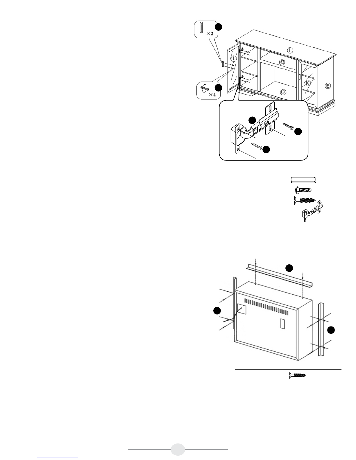
Step 9
Locate the left door (L). Place the rounded part of
the door hinge (NN) into the recessed area on
the left door (L). Using 2 small screws (EE), secure
the hinge to the door. Line up the left door (L) and
the hinge with the holes on the inside of the left
side panel exterior (E). Using 2 small screws (EE),
secure the door hinge (NN) to the left side panel
exterior (E). Repeat for the other door hinge on the
left door. Tighten all the small screws (EE) on both
door hinges until secure. Repeat for the right side
door (K).
Note: If the doors need leveling, adjust the 2
screws on the door hinge as needed.
Locate a handle (FF). Line up the holes in the
handle (FF) with the holes in a door. Insert 2
handle screws (LL) through the door and into
the handle (FF). Tighten handle screws (LL) until
secure. Repeat for the other handle (FF).
FF
LL
NN
EE
x8
EE
x8
Hardware Used
FF Handle x 2
LL Handle Screw x 4
EE Small Screw x 16
NN Door Hinge x 4
Step 10
Trim pieces for the firebox insert are provided
to close any gaps between the insert and the
mantel. Attach the firebox insert trim pieces to
firebox insert using 2 screws (MM) on the top and
2 sides. Once the trim pieces are secure, slide
firebox insert into the mantel from the back. Once
the firebox is in place and square with the mantel
opening, secure the 2 side firebox insert trim
pieces to the mantel using 2 screws (MM) on each
piece.
NOTE: If there is no room to get a screwdriver
between the insert and the mantel, the screws do
not have to be attached to the mantel. The firebox
insert will be secured in the next step. The trim
pieces are for appearance only.
MM
MM
MM
Hardware Used
MM Small Screw x 10
7
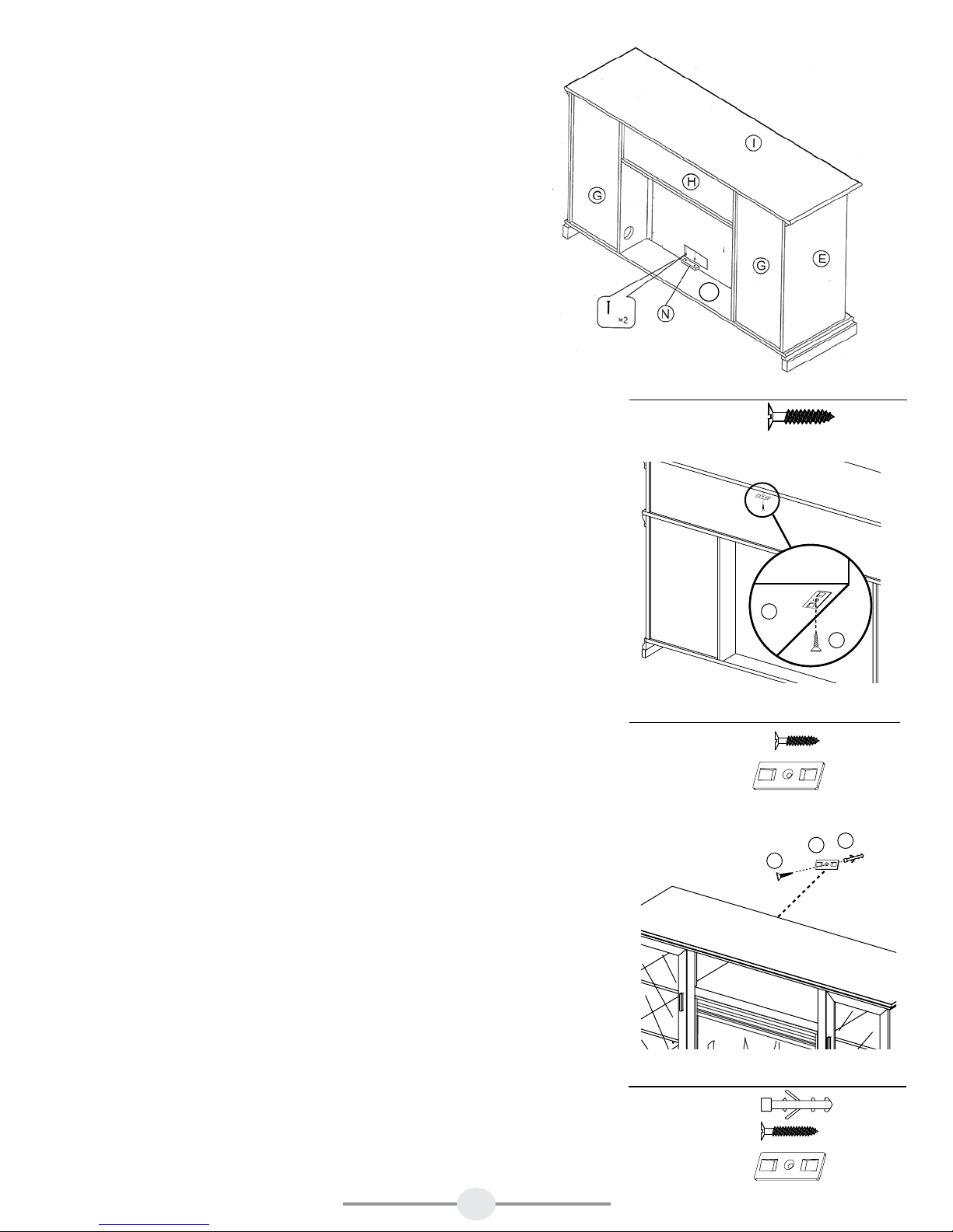
Step 11
Locate the firebox insert. Insert the firebox from
the rear of the mantel assembly. Once the firebox
insert is in place and secure, locate the firebox
brace (N). Place the firebox brace (N) up against
the firebox insert making sure you don’t cover any
air venting. Once the firebox brace (N) is snug,
secure it to the base (D) using 2 small screws (EE).
Your fireplace insert is now sitting firmly in place.
You must attach the anti-tipping device to the mantel
and the wall. This device is a safety feature that
will prevent the mantel from tipping over. Applied
weight may cause mantel imbalance.
D
Hardware Used
EE Small Screw x 2
Step 12
Attach one of the mounting brackets (II) securely to
the back underside edge of the mantel. Use 1 small
screws (EE) to make sure it is secure.
Step 13
Determine where mantel is to be placed and mark
location on the wall for the mounting bracket (II)
screw holes. The mounting bracket (II) on the wall
should be positioned horizontally. Insert a wall
anchor (JJ) into each screw hole in the wall. Place
the mounting bracket (II) over the marks on the wall
and use a large screw (KK) to securely attach the
mounting bracket (II) to wall.
EDGE OF
MANTEL
BRACKE
T
I I
Hardware Used
EE Small Screw x 1
Mounting
II
Bracket
KK
Hardware Used
JJ Wall Anchor x 1
KK Large Screw x 1
Mounting
II
Bracket
II
SMALL
SCREW
EE
JJ
WALL
x 1
x 1
8

Step 14
Place the mantel so the mounting bracket (II) on the back of the
mantel is in line with the mounting bracket (II) on the wall. Place an
end of the nylon strap (HH) down through each bracket. Bring both
ends together and slide the end of the nylon strap (HH) through the
slot in the other end until snug. Pull down on the end until it locks
into the slot. Check to make sure the nylon strap (HH) is securely
laced and locked to the mounting brackets (II).
WARNING: Young children may be injured by tipping furniture.
The use of a tipping restraint is highly recommended. This
hardware, when properly installed, could provide protection
against the unexpected tipping of furniture due to improper use.
MANTEL
Hardware Used
HH Nylon Strap x 1
WALL
GG
WARNING: THIS PRODUCT IS ONLY A DETERRENT. IT IS NOT
A SUBSTITUTE FOR PROPER ADULT SUPERVISION.
CAUTION:
This unit is intended for use only
with the products and maximum weights
indicated. Use with other products or products
heavier than the maximum weights indicated
may result in instability causing possible injury.
Note: Flat Panel TVs with base support should
be placed squarely in the center of the stand
with no overhang on any side.
MAXIMUM LOAD
30 lb. (13.6 kg)
CARE AND MAINTENANCE
FIT UP TO 55" PLASMA/
LCD TELEVISIONS
MAXIMUM LOAD
90 lb. (40.8 kg)
MAXIMUM LOAD
5 lb. (2.3 kg)
1. Dust your fireplace mantel regularly with a soft non-lint producing cloth or household dusting
product.
2. You can clean your fireplace insert with a gentle non-abrasive household cleaner. Make sure to dry it
immediately with a soft cloth or towel.
This mantel comes with a touch up pen for any minor repairs.
9

WARRANTY
Greenway Home Products is pleased to offer in-home warranty repairs. Please refer to your Firebox Use and Care Guide for warranty
information on your Firebox.
DO NOT RETURN THIS PRODUCT TO THE STORE:
Please contact Customer Service at: 1-866-253-0447
Monday to Thursday from 8:30AM to 5:00PM (EST), Friday from 8:30AM to 4:00PM (EST)
Web: www.greenwayhp.com
Email: support@greenwayhp.com
Canada: 400 Southgate Dr., Guelph, Ontario, Canada, N1G 4P5
USA:
1270 Flagship Dr., Perrysburg, Ohio, USA, 43551
Limited Warranty Definitions:
Greenway Home Products:
(Greenway) Manufacturer.
Mantel: Mantel manufactured by Greenway Home Products.
Purchaser: Purchaser of the Mantel
Distributor: Facility authorized to sell Greenway Home Products.
Warranty Card Greenway Home Products Limited Warranty Registration Card identifying the Purchaser and product model.
Greenway Limited Warranty:
Greenway warrants to the Purchaser that the Mantel is free from defects in material and workmanship, under normal use and service, for
1 year (1 year limited parts) from the date of purchase.
All warranty repairs must be preauthorized by Greenway Home Products. Greenway will, at its’ option, replace or repair free of charge
any defective part, which the Purchaser shall notify their Distributor or Greenway Home Products within the warranty period. The obligation
of Greenway Home Products under this warranty, is expressly limited to such replacement or repairs.
The provisions of this limited warranty shall not apply to the following:
1. Accidents.
2. Unauthorized repairs or alterations.
3.
Normal maintenance.
4. Changes made to other units manufactured after this mantel was manufactured.
5. Incidental damages caused by failure of the mantel such as inconvenience or loss of use.
6.
Improper installation.
The provisions of this limited warranty shall not apply to deterioration due to wear and exposure beyond the following limitations:
1. For 180 days from the date of purchase for exterior finished surfaces.
Due to the properties of natural wood, Greenway Home Products makes no warranty against mineraling of wood components.
Greenway Limited Warranty is void unless the following conditions are adhered to:
1. Warranty registration must be completed and returned to a Greenway Home Products.
2. All warranty repairs must be preauthorized by a Greenway repair facility.
3. Greenway reserves the right to inspect defective parts that have been replaced under warranty. Dealer is expected to hold
defective parts for 60 days.
4. Only parts and accessories and other materials, available through Greenway Home Products are to be used in the performance
of warranty service.
5. Purchasers are responsible for presenting/notifying their Distributor as soon a problem exists. The warranty repairs should be
completed in a reasonable amount of time from the date of authorization. Not to exceed 30 days past notification.
This limited warranty is expressly in lieu of any other expressed or implied warranty, including any implied warranty or merchantability
or fitness for a particular purpose and of any obligations or liabilities on Greenway Home Products which neither assumes nor
authorizes any other person to assume for it any other liability in connection with the Mantel manufactured by it.
The warranty is null and void if used in commercial or industrial applications.
10

CONSEILS POUR L’ASSEMBLAGE DE VOTRE NOUVEAU MANTEAU
Avant d’entreprendre l’assemblage, trouvez les instructions et les articles de quincaillerie. Sortez les
composants et comparez-les par rapport aux schémas ci-dessous. Assurez-vous que vous avez toutes les
pièces et que vous pouvez les identifier.
L’aide d’une autre personne est toujours bienvenue. Assemblez votre manteau avec l’aide d’un autre
adulte si c’est possible. Certains composants sont lourds et l’autre personne pourra les tenir. Il vous faudra
environ 30-60 minutes pour faire l’assemblage.
I
G
H
E
J
L
Pièce
Panneau latéral intérieur
A
Panneau latéral intérieur gauche
B
Description Qté
droit
C Tablette centrale 1
D Base 1
E Panneau Extérieur 2
Garniture pour Étagère Central
F
G Panneau arrière 2
Panneau arrière de l'unité de rangement
H
J
B
M
Numéro de pièce
ZZ.2500SCH.01
1
ZZ.2500SCH.02
1
ZZ.2500SCH.03
ZZ.2500SCH.04
ZZ.2500SCH.05
ZZ.2500SCH.06
1
ZZ.2500SCH.07
ZZ.2500SCH.08
1
O
C
F
J
A
N
K
J
M
D
Pièce
Description Qté
I Dessus 1
J Tablette 4
K Porte droite 1
L Porte gauche 1
Garniture pour Panneau Intérieur
M
Traverse pour foyer encastrable
N
O Support de Base 1
G
E
Numéro de pièce
ZZ.2500SCH.09
ZZ.2500SCH.10
ZZ.2500SCH.11
ZZ.2500SCH.12
ZZ.2500SCH.13
2
ZZ.2500SCH.14
1
ZZ.2500SCH.15
1

QUINCAILLERIE
AA BB CC DD EE
Attache
Camloc
Capuchon en
plastique
Taquet de
xation
Qté : 32
Qté : 32
Qté : 16
Vis Camloc
Qté : 32
HH
II JJ KK LL
Petit Vis
Qté : 19
FF
Poignée
Qté : 2
MM
Courroie de
nylon
Qté : 1
NN
Charnière
de porte
Traverse
Qté : 2
d’ancrage
PP
Crayon à
retouche
Cheville
Qté : 1
Gros Vis
Qté : 1
Poignée
Vis
Qté : 4
Vis pour
Panneau
Arrière
Qté : 44
Qté : 4
Qté : 1
2

PRÉPAREZ-VOUS À COMMENCER
Avant de commencer l’assemblage, défaites les pièces de l’emballage à l’aide de ciseaux. NE VOUS SERVEZ
PAS d'un couteau à lame rétractable ni d’un couteau de précision, car ces derniers pourraient atteindre les pièces
du manteau à l’intérieur de la boîte et endommager le fini. Dans l’emballage, repérez le sac de quincaillerie fixé
à l’extrémité supérieure de la boîte à l’aide de ruban adhésif. Assurez-vous de ne jeter AUCUNE pièce.
Étape 1
Prenez la pièce de garniture de la tablette (F). Insérez trois
goujons Camloc (AA) dans les trous situés à l’arrière de la
pièce de garniture. L’arrière est le côté non fini.
Prenez la tablette centrale (C). Assurez-vous que le côté fini
de la tablette centrale est placé face vers le haut et que le trou
de souris est à l’arrière. Insérez trois attaches Camloc (BB)
dans les trous situés sur le côté inférieur de la tablette centrale
(C). Assurez-vous que les flèches sur les attaches Camloc (BB)
AA
pointent en direction de la pièce de garniture. Alignez les
goujons Camloc (AA) de la pièce de garniture avec les trous
situés sur le rebord avant de la tablette centrale (C). Posez la
pièce de garniture (F) sur le devant de la tablette centrale (C)
BB
CC
et appuyez dessus jusqu’à ce qu’elle soit parfaitement insérée.
Serrez les attaches Camloc (BB). Évitez de serrer excessivement
les attaches Camloc afin de ne pas les abîmer.
Placez les capuchons (CC) sur les trois attaches Camloc.
Quincaillerie utilisée
AA Vis Camloc x 3
BB Attache Camloc x 3
CC Capuchon x 3
Étape 2
Prenez la pièce de garniture du panneau latéral intérieur
gauche (M). Insérez trois goujons Camloc (AA) dans les trous
situés à l’arrière de la pièce de garniture (M). L’arrière est le
côté non fini.
Prenez le panneau latéral intérieur gauche (B). Assurez-vous
que le côté fini du panneau latéral intérieur gauche (B) est
placé face vers l’extérieur et que le trou de souris est en bas.
Insérez des attaches Camloc (BB) dans les trous situés du côté
droit du panneau latéral intérieur gauche (B). Assurez-vous que
les flèches sur les attaches Camloc (BB) pointent en direction
de la pièce de garniture (M). Alignez les goujons Camloc (AA)
insérés dans la pièce de garniture (M) avec les trous situés
sur le rebord du panneau latéral intérieur gauche (B). Posez
la pièce de garniture (M) sur le devant du panneau latéral
intérieur gauche (B) et appuyez dessus jusqu’à ce qu’elle soit
parfaitement insérée. Serrez les attaches Camloc (BB). Évitez
de serrer excessivement les attaches Camloc afin de ne pas les
abîmer.
Faites de même pour le panneau latéral intérieur droit (A).
Placez les capuchons (CC) sur les six attaches Camloc.
AA
BB
CC
Quincaillerie utilisée
AA Vis Camloc x 6
BB Attache Camloc x 6
CC Capuchon x 6
3

Étape 3
Prenez la base (D). Insérez trois goujons Camloc
(AA) dans les trous situés sous la base (D). Prenez
le support de la base (O). Insérez trois attaches
Camloc (BB) dans les trous situés à l’avant du
support de la base (O). L’arrière est le côté non
fini. Assurez-vous que les flèches sur les attaches
Camloc (BB) pointent vers le haut en direction de
la base (D). Posez le support de la base (O) sur
la base (D) et appuyez dessus jusqu’à ce qu’il soit
parfaitement inséré. Serrez les attaches Camloc
(BB). Évitez de serrer excessivement les attaches
Camloc (BB) afin de ne pas les abîmer.
BB
CC
AA
Placez les capuchons (CC) sur les trois attaches
Camloc (BB).
Étape 4
Prenez le panneau latéral intérieur gauche (B).
Insérez deux goujons Camloc (AA) dans les trous
situés à l’intérieur du panneau latéral intérieur
gauche (B). Insérez deux attaches Camloc (AA)
sur le côté inférieur de la tablette centrale (C).
Assurez-vous que les flèches sur les attaches
Camloc (BB) pointent en direction du panneau
latéral intérieur gauche (B). Poussez le panneau
latéral intérieur gauche (B) contre la tablette
centrale (C) jusqu’à ce qu’il soit parfaitement
inséré. Serrez les attaches Camloc (BB). Évitez de
serrer excessivement les attaches Camloc afin de
ne pas les abîmer.
Quincaillerie utilisée
AA Vis Camloc x 3
BB Attache Camloc x 3
CC Capuchon x 3
AA
BB
CC
Quincaillerie utilisée
AA Vis Camloc x 4
BB Attache Camloc x 4
CC Capuchon x 4
Faites de même pour le panneau latéral intérieur
droit (A).
Placez les capuchons (CC) sur les quatre attaches
Camloc (BB) du côté inférieur de la tablette
centrale.
4

Étape 5
Insérez huit goujons Camloc (AA) dans les huit
trous de la base (D), tel qu’il est illustré. Insérez
deux attaches Camloc (BB) dans la partie extérieure
inférieure des panneaux latéraux intérieurs gauche
(B) et droit (A). Insérez deux attaches Camloc (BB)
dans la partie intérieure inférieure des panneaux
latéraux extérieurs gauche et droit (E). Assurez-vous
que les flèches sur les attaches Camloc pointent
vers le bas en direction de la base.
E
Appuyez les quatre panneaux contre la base
(D) jusqu'à ce qu'ils soient parfaitement insérés.
Serrez les attaches Camloc (BB). Évitez de serrer
excessivement les attaches Camloc afin de ne pas
les abîmer.
Placez les capuchons (CC) sur les huit attaches
Camloc (BB).
Étape 6
Prenez le dessus (I). Assurez-vous que le côté fini
est vers le haut. Insérez huit goujons Camloc (AA)
dans les trous situés du côté inférieur du dessus (I).
Insérez deux attaches Camloc (BB) du côté intérieur
supérieur du panneau latéral extérieur gauche
(E) et du panneau latéral intérieur gauche (B).
Recommencez, cette fois pour le panneau latéral
intérieur droit (A) et le panneau latéral extérieur
droit (E). Assurez-vous que les flèches sur toutes les
attaches Camloc pointent vers le haut en direction
du dessus (I).
Assurez-vous que les goujons Camloc (AA) sont
alignés avec les trous situés sur le dessus des
panneaux intérieur et extérieur (A, B et E). Appuyez
sur le dessus (I) jusqu’à ce qu’il soit parfaitement
inséré. Serrez les attaches Camloc (BB). Évitez de
serrer excessivement les attaches Camloc afin de ne
pas les abîmer.
AA
AA
DD
BB
CC
Quincaillerie utilisée
AA Vis Camloc x 8
BB Attache Camloc x 8
CC Capuchon x 8
E
BB
CC
Quincaillerie utilisée
AA Vis Camloc x 8
BB Attache Camloc x 8
CC Capuchon x 8
DD Taquet de fixation x 16
Insérez 16 taquets de fixation (DD) à l’intérieur des
espaces de rangement gauche et droit.
5

Étape 7
Prenez les deux panneaux arrière (G) et le
panneau arrière de l'unité de rangement (H).
Assurez-vous que les côtés finis des panneaux
sont orientés vers le manteau. Placez l'un des
panneaux arrière (G) de façon à l'aligner
parfaitement avec l'arrière du panneau latéral
intérieur gauche (B) et l'arrière du panneau latéral
extérieur gauche (E). Fixez-le à l’aide des 12 vis
du panneau arrière (MM); cinq à la verticale de
chaque côté et deux à l’horizontale dans le haut et
le bas. Serrez-les fermement. Faites de même pour
l’autre panneau arrière (G).
Placez le panneau arrière de l'unité de rangement
(H) de façon à l'aligner parfaitement avec l'arrière
des panneaux latéraux intérieurs gauche (A) et
droit (B) et avec le dessus (I). Fixez-le à l’aide des
10 vis du panneau arrière (MM); quatre dans le
haut et le bas et une de chaque côté. Serrez-les
fermement.
G
MM
Quincaillerie utilisée
MM
H
Vis pour
Panneau Arrière
G
x 34
Étape 8
Prenez les quatre tablettes (J). Placez les tablettes
(J) sur les taquets de fixation (DD) de chaque
espace de rangement. Assurez-vous que les
tablettes sont de niveau.
6

Étape 9
Trouvez la porte de gauche (L). Placez la partie
arrondie de la charnière de porte (NN) dans
la zone en retrait sur la porte de gauche (L).
Aide de 2 petites vis (EE), sûr de la charnière
de la porte. Aligner la porte de gauche (L) et la
charnière sur les trous à l'intérieur de l'extérieur
du panneau latéral gauche (E). Aide de 2 petites
vis (EE), assurer la charnière de porte (NN) à
l'extérieur du panneau latéral gauche (E). Répétez
l'opération pour l'autre porte charnière sur la
porte de gauche. Serrer toutes les petites vis (EE)
sur les deux charnières de la porte jusqu'à ce que
sécurisé. Répétez l'opération pour la porte de
droite (K).
Note: Si les portes ont besoin de mise à niveau,
ajustez les 2 vis sur la charnière de porte.
Prenez la poignée (FF). Alignez les trous de la
poignée (FF) à ceux d’une porte. Insérez les
deux vis de la poignée (LL) à travers la porte et
la poignée (FF). Serrez les vis de la poignée (LL)
jusqu’à ce qu’elle soit bien en place. Faites de
même pour l’autre poignée (FF).
FF
LL
NN
EE
x8
EE
x8
Quincaillerie utilisée
FF Poignée x 2
LL Poignée Vis x 4
EE Petit Vis x 16
NN Charnière de porte x 4
Étape 10
Pièces de finition pour l'insert foyer sont fournis
pour combler les lacunes entre le foyer et le
mantel. Fixer le support de garniture foyer pièces
à insérer foyer avec 2 vis (MM) sur la face
supérieure et 2. Une fois les pièces spéciales sont
sécurisés, insérez foyer glisser dans la cheminée
à l'arrière. Une fois le foyer est en place et de
la place avec l'ouverture de cheminée, d'assurer
l'insertion latérale 2 pièces de garniture foyer à la
cheminée avec 2 vis (MM) sur chaque morceau.
NOTE: S'il n'y a pas de place pour obtenir un
tournevis entre le foyer et le mantel, les vis ne
doivent pas être attaché au mantel. Le foyer sera
assurée dans l'étape suivante. Les pièces de
finition sont pour l'apparence seulement.
MM
MM
MM
Quincaillerie utilisée
MM Petit Vis x 10
7

Étape 11
Prenez le foyer encastrable. Insérez le foyer
par l'arrière du manteau. Une fois que le foyer
encastrable est bien en place, prenez la traverse
pour foyer (N). Appuyez la traverse pour foyer
(N) contre le foyer encastrable en veillant à ne
pas obstruer la bouche d’aération. Une fois que
la traverse pour foyer (N) est en place, fixez-la à
la base (D) à l’aide de deux petites vis (EE). Votre
foyer encastrable est maintenant solidement fixé.
Vous devez fixer le dispositif antibasculement
au manteau et au mur. Ce dispositif de sécurité
empêche le manteau de basculer. L’application
d’un poids pourrait déséquilibrer le manteau.
Étape 12
Fixez solidement un support de fixation (II) au
rebord arrière du manteau. Servez-vous d’une
petite vis (EE) afin de bien fixer ce support.
D
Quincaillerie utilisée
EE Petit Vis x 2
REBORD DU
MANTEAU
TRAVERSE
I I
Quincaillerie utilisée
EE Petit Vis x 1
II Traverse x 1
PETIT VIS
EE
Étape 13
Déterminez l’emplacement voulu du manteau, puis
faites une marque sur le mur à l’endroit où entreront
les petites vis du support de montage (II). Posez le
support de montage (II) horizontalement au mur.
Insérez une cheville d’ancrage (JJ) dans chaque
trou de vis percé dans le mur. Placez le support
de fixation (II) par-dessus les marques sur le mur,
puis servez-vous d’une grande vis (KK) pour fixer
solidement le support (II) au mur.
JJ
II
KK
MUR
Quincaillerie utilisée
JJ Cheville d’ancrage x 1
KK Gros Vis x 1
II Traverse x 1
8

Étape 14
Disposez le manteau de façon que le support de fixation (II) situé
à l’arrière du manteau soit aligné avec le support (II) fixé au mur.
Faites passer une extrémité de la courroie en nylon (HH) à travers
les supports. Alignez les deux extrémités de la courroie en nylon
(HH), puis insérez le côté plat dans l'ouverture de façon à bien
l’ajuster. Tirez sur l'extrémité plate jusqu’à ce qu’elle se bloque dans
la boucle. Assurez-vous que la courroie (HH) est solidement attachée
aux supports de fixation (II).
AVERTISSEMENT : Le basculement d’un meuble peut blesser les
jeunes enfants. Il est fortement recommandé d’utiliser un dispositif
antibasculement. Un tel article, s'il est bien installé, fournit une
protection contre le basculement accidentel d’un meuble en cas
d’usage inadéquat.
MANTEAU
Quincaillerie utilisée
HH Courroie de nylon x 1
MUR
GG
AVERTISSEMENT : CETTE MESURE DE SÉCURITÉ
SUPPLÉMENTAIRE NE REMPLACE
PAS LA SUPERVISION D’UN ADULTE.
MISE EN GARDE :
Cette unité est uniquement
compatible avec les produits spécifiés et ne
peut supporter que la charge maximale indiquée.
Le fait d’utiliser cette unité avec d’autres produits
ou avec des produits dont le poids excède la
charge maximale indiquée peut entraîner de
l’instabilité et causer des blessures.
Remarque : Les téléviseurs à écran plat munis
d'une base de soutien doivent être placés
complètement au centre du support sans
qu'aucune partie de la base ne dépasse.
CHARGE MAXIMALE
DE 13,6 KG (30 LB)
ENTRETIEN
CONVIENT AUX
TÉLÉVISEURS À ÉCRAN
PLASMA OU ACL DE
55 PO OU MOINS
CHARGE MAXIMALE DE
40,8 KG (90 LB)
CHARGE MAXIMALE
DE 2,3 KG (5 LB)
1. Époussetez régulièrement le manteau à l’aide d’un linge doux et non pelucheux ou d’un accessoire
pour l’époussetage domestique.
2. Vous pouvez nettoyer le foyer encastrable à l’aide d’un nettoyant doux et non abrasif. Essuyez-le
immédiatement à l’aide d’un linge doux ou d’une serviette.
L’emballage du manteau contient un crayon à retouche (RR) pour les réparations mineures.
9

GARANTIE
Greenway Home Products est heureux de vous offrir à domicile, les services de réparations sous garantie. Voir le Manuel d'utilisation
et d'entretien du foyer pour d’amples renseignements au sujet de la garantie.
NE RAPPORTEZ PAS CET APPAREIL AU MAGASIN :
Communiquez avec le Service à la clientèle au numéro sans frais suivant 1-866-253-0447
Du lundi au jeudi, de 8 h 30 à 17 h (HNE), le vendredi, de 8 h 30 à 16 h (HNE)
Site web: www.greenwayhp.com Courriel: support@greenwayhp.com
Au Canada: 400 Southgate Dr., Guelph, Ontario, Canada, N1G 4P5
Aux États-Unis:
Définitions s’appliquant à la garantie limitée
Greenway Home Products:
(Greenway) Fabricant.
Manteau: Manteau de cheminée fabriqué par Greenway Home Products.
Acheteur: Acheteur du manteau de cheminée
Distributeur: Établissement autorisé à vendre les produits Greenway Home Products.
Fiche de garantie: Fiche de garantie limitée de Greenway Home Products identifiant l’acheteur et le modèle du produit.
Garantie limitée de Greenway:
Greenway garantit à l’acheteur du manteau de cheminée que le produit est libre de défaut tant au niveau des matériaux que de la
fabrication, sous des conditions normales d’utilisation; la garantie est en vigueur 1 an (garantie limitée de un an sur les pièces) à partir
de la date d’achat.
Toutes les réparations faites sous garantie doivent être autorisées par Greenway Home Products. Greenway pourra, à sa discretion,
remplacer ou réparer gratuitement la pièce défectueuse, à condition que l’acheteur avise son distributeur ou Greenway Home Products
au cours de la période de garantie. L’obligation de Greenway Home Products en vertu de la garantie est expressément limitée à ce
remplacement ou à ces réparations.
1270 Flagship Dr., Perrysburg, Ohio, USA, 43551
Les dispositions de cette garantie limitée ne s’appliquent pas aux dispositions suivantes:
1. Accidents.
2. Réparations ou modifications non autorisées.
3. Entretien normal.
4. Changements apportés aux autres unités fabriquées après la fabrication du manteau de cheminée.
5. Les dommages secondaires causés par une une panne du manteau de cheminée, tels que inconvénients ou la perte d’usage.
6. Mauvaise installation.
Les dispositions de cette garantie limitée ne s’appliquent pas aux dommages provenant de l’utilisation ou par des conditions au-delà
des limites suivantes :
1. Pendant 180 jours à partir de la date d’achat pour les surfaces extérieures peintes.Compte tenu des propriétés du bois
naturel, Greenway Home Products ne donne aucune garantie contre la minéralisation des composants du bois.
La garantie limitée de Greenway est sans valeur si les conditions suivantes ne sont pas observées:
1. La fiche de garantie doit être remplie et envoyée à Greenway Home Products.
2. Toutes les réparations sous garantie doivent être autorisées d’avance par les installations de réparation de la société
Greenway.
3. Greenway se réserve le droit d’inspecter les composants défectueux remplacés sous garantie. le distributeur doit conserver
les pièces défectueuses pendant 60 jours.
4. Seul les pièces et les accessoires et tout autre matériel disponible par l’entremise de Greenway Home Products doivent être
utilisés pour exécuter le service sous garantie.
5. Il incombe aux acheteurs de se présenter/aviser leur détaillant dès que le problème se manifeste. Les réparations sous
garantie doivent être faites dans un temps raisonnable à partir de la date d’autorisation. La réparation ne doit pas dépasser
30 jours après la réception de l’avis.
Cette garantie limitée remplace toute autre garantie exprès ou tacite, y compris toute garantie tacite ou de qualité marchande ou de
convenance en fonction d’une application particulière et de toute obligation ou responsabilité afférente aux produits de Greenway
Home Products qui n’assume ni autorise aucune autre personne à assumer pour Greenway une responsabilité relatif à la fabrication
du manteau de cheminée.
Cette garantie est nulle et sans effet si l’appareil est utilisé dans des applications commerciales
ou industrielles.
10

CONSEJOS PARA EL ENSAMBLADO DE SU NUEVA REPISA DE CHIMENEA
Antes de comenzar el ensamblado, localice las instrucciones y los accesorios. Saque todos los componentes
y compárelos con los diagramas que aparecen a continuación. Asegúrese de tener todos los componentes
y que puede identificarlos.
Siempre es bueno tener alguien que le ayude; de ser posible consiga que un adulto le ayude a ensamblar
su repisa de chimenea. Algunas piezas son pesadas y necesitará que se las sostenga un ayudante. El
tiempo de ensamblado tomará de 30 a 60 minutos aproximadamente.
I
G
H
E
J
L
Pieza
A
B
Panel lateral derecho interior
Panel lateral izquierdo interior
Descripción
C Estante central 1
D Base 1
E Exterior Grupo 2
Plataforma Central borde decorativo
F
G Panel posterior 2
Panel posterior de almacenamiento
H
J
M
Cant.
Número de pieza
ZZ.2500SCH.01
1
ZZ.2500SCH.02
1
ZZ.2500SCH.03
ZZ.2500SCH.04
ZZ.2500SCH.05
ZZ.2500SCH.06
1
ZZ.2500SCH.07
ZZ.2500SCH.08
1
B
F
C
G
J
A
N
K
J
E
M
D
O
Cant.
Pieza
Descripción
I Parte superior 1
J Estante 4
K Puerta derecha 1
L Puerta izquierda 1
Panel de Interior el borde decorativo
M
Abrazadera del accesorio para chimenea
N
O Base de apoyo 1
Número de pieza
ZZ.2500SCH.09
ZZ.2500SCH.10
ZZ.2500SCH.11
ZZ.2500SCH.12
ZZ.2500SCH.13
2
ZZ.2500SCH.14
1
ZZ.2500SCH.15
1

ADITAMENTOS
AA BB CC DD EE
Cerrojo
de leva
Tapa de leva
de plástico
Estaca de
montaje
Cant. 32
Cant. 32
Cant. 16
Espiga para
cerrojo de
leva
Cant. 32
HH
II JJ KK LL
Tornillo
pequeño
Cant. 19
FF
Manija
Cant. 2
MM
Correa de
nailon
Cant. 1
Puerta de
Bisagra
Abrazadera
de montaje
Cant. 2
Aplicador de
retoque
expansión de
PPNN
Ancla de
pared
Cant. 1
Tornillo
grande
Cant. 1
Mango
Tornillo
Cant. 4
Volver
tornillos del
panel
Cant. 44
Cant. 4
Cant. 1
2

PREPÁRESE A EMPEZAR
Antes de ensamblar, use tijeras para retirar el envoltorio de las piezas del empaque. NO use un
cortador de cajas o un cuchillo utilitario debido a que puede cortar las piezas de la repisa para
chimenea dentro de la caja y dañar el acabado. Verifique la bolsa de aditamentos que se encuentra
dentro del empaque, unida a la caja superior. Asegúrese de NO desechar ninguna pieza.
Paso 1
Ubique la pieza con reborde del estante central (F). Inserte
3 espigas para cerrojo de leva (AA) en la parte posterior
de la pieza con reborde. El lado posterior es el lado sin
acabado.
Ubique el estante central (C). Asegúrese de que el lado
acabado del estante central mire hacia arriba con el orificio
de ratón en la parte posterior. Inserte 3 cerrojos de leva
(BB) en los orificios de la parte inferior del estante central
AA
(C). Asegúrese de que las flechas de los cerrojos de leva
(BB) apunten hacia la pieza con reborde. Alinee las espigas
para cerrojo de leva (AA) de la pieza con reborde con
los orificios del borde frontal del estante central (C). Una
BB
CC
mediante presión la pieza con reborde (F) con el estante
central (C) hasta que queden al ras. Apriete los cerrojos de
leva (BB). No los apriete demasiado para evitar dañarlos.
Coloque tapas de leva (CC) sobre los 3 cerrojos de leva.
Aditamentos utilizados
Espiga para
AA
cerrojo de leva
BB Cerrojo de leva x 3
x 3
Paso 2
Ubique la pieza de reborde del panel lateral izquierdo
interior (M). Inserte 3 espigas para cerrojo de leva (AA)
en la parte posterior de la pieza con reborde (M). El lado
posterior es el lado sin acabado.
Ubique el panel lateral izquierdo interior (B). Asegúrese de
que el lado acabado del panel lateral izquierdo interior
(B) mire hacia afuera con el orificio de ratón en la parte
inferior. Inserte cerrojos de leva (BB) en los orificios del
costado derecho del panel lateral izquierdo interior (B).
Asegúrese de que las flechas de los cerrojos de leva (BB)
apunten hacia la pieza con reborde (M). Alinee las espigas
para cerrojo de leva (AA) en la pieza con reborde (M) con
los orificios en el borde del panel lateral izquierdo interior
(B). Una mediante presión la pieza con reborde (M) con el
panel lateral izquierdo interior (B) hasta que queden al ras.
Apriete los cerrojos de leva (BB). No los apriete demasiado
para evitar dañarlos.
Repita el procedimiento para el panel lateral derecho
interior (A).
Coloque tapas de leva (CC) sobre los 6 cerrojos de leva.
Tapa de leva
AA
CC
de plástico
BB
CC
Aditamentos utilizados
Espiga para
AA
cerrojo de leva
BB Cerrojo de leva x 6
Tapa de leva
CC
de plástico
x 3
x 6
x 6
3

Paso 3
Ubique la base (D). Inserte 3 espigas del cerrojo
de leva (AA) en los orificios debajo de la base
(D). Coloque el soporte de la base (O). Inserte
3 cerrojos de leva (BB) en los orificios de la
parte frontal del soporte de la base (O). El lado
posterior es el lado sin acabado. Asegúrese
de que las flechas de los cerrojos de leva (BB)
apunten hacia arriba, en dirección a la base (D).
Una mediante presión el soporte de la base (O)
con la base (D) hasta que queden al ras. Apriete
los cerrojos de leva (BB). No apriete demasiado
los cerrojos de leva (BB) para evitar dañarlos.
BB
CC
AA
Coloque tapas de leva (CC) sobre los 3 cerrojos
de leva (BB).
Paso 4
Ubique el panel lateral izquierdo interior (B).
Inserte 2 espigas para cerrojo de leva (AA) en
los orificios de la parte interna del panel lateral
izquierdo interior (B). Inserte 2 cerrojos de leva
(AA) en la parte inferior del estante central (C).
Asegúrese de que las flechas de los cerrojos de
leva (BB) apunten hacia el panel lateral izquierdo
interior (B). Una mediante presión el panel lateral
izquierdo interior (B) con el estante central (C)
hasta que queden al ras. Apriete los cerrojos de
leva (BB). No los apriete demasiado para evitar
dañarlos.
Repita el procedimiento para el panel lateral
derecho interior (A).
AA
Aditamentos utilizados
Espiga para
AA
cerrojo de leva
BB Cerrojo de leva x 3
Tapa de leva
CC
de plástico
BB
CC
Aditamentos utilizados
Espiga para
AA
cerrojo de leva
BB Cerrojo de leva x 4
Tapa de leva
CC
de plástico
x 3
x 3
x 4
x 4
Coloque las tapas de leva (CC) sobre los 4
cerrojos de leva (BB) en la parte inferior del
estante central.
4

Paso 5
Inserte 8 espigas para cerrojo de leva (AA) en los
8 orificios que se muestran en la base (D). Inserte 2
cerrojos de leva (BB) en la parte exterior inferior de
cada panel lateral interior, tanto izquierdo como
derecho (B y A). Inserte 2 cerrojos de leva (BB) en
la parte interior de la parte inferior de cada panel
lateral exterior, tanto izquierdo como derecho (E).
Asegúrese de que las flechas de los cerrojos de
leva apunten hacia abajo en dirección a la base.
E
Presione los 4 paneles hacia abajo en la base
(D) hasta que estén al ras. Apriete los cerrojos de
leva (BB). No los apriete demasiado para evitar
dañarlos.
Coloque tapas de leva (CC) sobre los 8 cerrojos
de leva (BB).
Paso 6
Ubique la parte superior (I). Asegúrese de que el
lado con acabado quede hacia arriba. Inserte 8
espigas para cerrojo de leva (AA) en los orificios
de la parte inferior de la cubierta (I). Inserte 2
cerrojos de leva (BB) en la parte superior interna
del panel lateral izquierdo exterior (E) y el panel
lateral izquierdo interior (B). Repita para el panel
lateral derecho interior (A) y el panel lateral
derecho exterior (E). Asegúrese de que todas las
flechas de los cerrojos de leva apunten hacia
arriba en dirección a la parte superior (I).
AA
AA
DD
BB
Aditamentos utilizados
Espiga para
AA
cerrojo de leva
BB Cerrojo de leva x 8
Tapa de leva
CC
de plástico
E
CC
CC
x 8
x 8
BB
Asegúrese de que las espigas para cerrojo de
leva (AA) se alineen con los orificios de la parte
superior de los paneles interiores y exteriores (A,
B y E). Presione la parte superior (I) hacia abajo
hasta que quede al ras. Apriete los cerrojos de
leva (BB). No los apriete demasiado para evitar
dañarlos.
Inserte 16 estacas de montaje (DD) en la parte
interior de las áreas de almacenamiento izquierda
y derecha.
Aditamentos utilizados
Espiga para
AA
cerrojo de leva
BB Cerrojo de leva x 8
Tapa de leva
CC
de plástico
Estaca de
DD
montaje
x 8
x 8
x 16
5

Paso 7
Ubique los 2 paneles posteriores (G) y el panel
posterior de almacenamiento (H). Asegúrese de
que los lados acabados de los paneles apunten
hacia la repisa para chimenea. Alinee un panel
posterior (G) de modo que quede al ras con la
parte posterior del panel lateral izquierdo interior
(B) y el panel lateral izquierdo exterior (E). Fije
con 12 tornillos para el panel posterior (MM): 5
bajo cada lado y 1 en la parte superior e inferior.
Apriete hasta lograr un ajuste firme. Repita este
procedimiento con el otro panel posterior (G).
G
H
G
Alinee el panel posterior de almacenamiento (H)
de modo que quede al ras con la parte posterior
de los paneles laterales interiores izquierdo y
derecho (A y B) y la parte superior (I). Fije con
10 tornillos para el panel posterior (MM): 4 a lo
largo de la parte superior e inferior y 1 a cada
lado. Apriete hasta lograr un ajuste firme.
Paso 8
Ubique los 4 estantes (J). Coloque los estantes (J)
en las estacas de montaje (DD) en cada área de
almacenamiento. Asegúrese de que los estantes
estén nivelados.
MM
Aditamentos utilizados
Volver tornillos
MM
del panel
x 34
6

Paso 9
Localice la puerta de la izquierda (L). Coloque
la parte redondeada de la bisagra de la puerta
(NN) en el área empotrada en la puerta de la
izquierda (L). Con 2 tornillos pequeños (EE), seguro
de la bisagra de la puerta. Alinee la puerta de la
izquierda (L) y la bisagra con los agujeros en el
interior del exterior del panel lateral izquierdo (E).
Con 2 tornillos pequeños (EE), asegurar la bisagra
de la puerta (NN) en el exterior del panel lateral
izquierdo (E). Repita el procedimiento para la otra
puerta de la bisagra de la puerta izquierda. Apriete
todos los tornillos pequeños (EE) en los dos bisagras
de la puerta hasta que quede firme. Repita el
procedimiento para la puerta lateral derecha (K).
Nota: Si las puertas necesitan nivelación, ajuste los
dos tornillos de la bisagra de la puerta, según sea
necesario.
Ubique la manija (FF). Alinee los orificios de la
manija (FF) con los orificios de una puerta. Inserte 2
tornillos para manija (LL) a través de la puerta y en
la manija (FF). Apriete los tornillos para manija (LL)
hasta que estén seguros. Repita la operación para la
otra manija (FF).
FF
LL
NN
EE
x8
EE
x8
Aditamentos utilizados
Manija
FF
LL Mango Tornillo x 4
EE Tornillo pequeño x 16
NN Puerta de Bisagra x 4
x 2
Paso 10
Piezas especiales para la inserción del fogón se
proporcionan para cerrar los vacíos entre el relleno
y la repisa de la chimenea. Coloque el inserto de
la caja de fuego molduras para insertar la caja de
fuego con 2 tornillos (MM) en la cara superior y
2. Una vez que las piezas decorativas se inserte
segura, fogones caer en la repisa de la parte
posterior. Una vez que la cámara de combustión
está en el lugar y la plaza con la abertura de la
chimenea, asegurar la inserción lateral 2 fogones
molduras de la chimenea con 2 tornillos (MM) en
cada pieza.
NOTA: Si no hay espacio para conseguir un
destornillador entre el relleno y la repisa de la
chimenea, los tornillos no tiene que ser conectado
a la chimenea. El inserto de caja de fuego se
garantizará en el próximo paso. Las piezas
decorativas son de apariencia.
MM
MM
MM
Aditamentos utilizados
MM Tornillo pequeño x 10
7

Paso 11
Ubique el accesorio de la cámara de combustión.
Inserte la cámara de combustión desde la
parte posterior del ensamble de la repisa para
chimenea. Una vez que el accesorio de la cámara
de combustión esté en su lugar y asegurado,
ubique el soporte de la cámara de combustión
(N). Coloque el soporte de la cámara de
combustión (N) hacia arriba y contra el accesorio
de la cámara de combustión, asegurándose de no
cubrir ninguna ventilación de aire. Una vez que
el soporte de la cámara de combustión (N) esté
ceñido, asegúrelo a la base (D) con 2 tornillos
pequeños (EE). El accesorio de la chimenea ahora
está bien ajustado en su lugar.
Debe fijar el dispositivo contra vuelcos a la repisa
para chimenea y a la pared. Este dispositivo es
una característica de seguridad que evitará que
la repisa para chimenea se vuelque. El peso que
se aplique puede desequilibrar la repisa para
chimenea.
Paso 12
Fije una de las abrazaderas de montaje (II)
firmemente al borde inferior posterior de la repisa
para chimenea. Use 1 tornillo pequeño (EE) para
asegurarla.
D
Aditamentos utilizados
EE Tornillo pequeño x 2
BORDE DE LA
CHIMENEA
ABRAZADERA
DE MONTAJE
I I
Aditamentos utilizados
EE Tornillo pequeño x 1
Abrazadera
II
de montaje
TORNILLO
PEQUEÑO
EE
x 1
Paso 13
Determine en qué lugar colocará la repisa para
chimenea y marque en la pared la ubicación para
los orificios de los tornillos para la abrazadera de
montaje (II). Se debe colocar la abrazadera de
montaje (II) en la pared de forma horizontal. Inserte
un ancla de expansión de pared (JJ) en cada
uno de los orificios para los tornillos en la pared.
Coloque la abrazadera de montaje (II) sobre las
marcas en la pared y use un tornillo grande (KK)
para fijar firmemente la abrazadera de montaje (II)
en la pared.
JJ
II
KK
PARED
Aditamentos utilizados
Ancla de expansión
JJ
de pared
KK Tornillo grande x 1
Abrazadera
II
de montaje
x 1
x 1
8

Paso 14
Coloque la repisa para chimenea de modo que la abrazadera
de montaje (II) en la parte posterior de la repisa para chimenea
esté en línea con la abrazadera de montaje (II) en la pared. Pase
un extremo de la correa de nailon (HH) por cada abrazadera.
Junte los extremos y deslice el extremo de la correa de nailon
(HH) por la ranura en el otro extremo hasta que esté ceñida. Jale
el extremo hasta que se asegure en la ranura. Verifique que la
correa de nailon (HH) esté firmemente ajustada y asegurada a las
abrazaderas de montaje (II).
ADVERTENCIA: Los niños pequeños pueden salir lesionados debido
a muebles que se vuelcan. Se recomienda en gran medida usar
accesorios que impiden los vuelcos. Estos aditamentos, cuando se
instalan adecuadamente, pueden brindar protección contra el vuelco
inesperado de muebles debido a un uso inadecuado.
REPISA
Aditamentos utilizados
HH Correa de nailon x 1
PARED
GG
ADVERTENCIA: ESTE PRODUCTO SIRVE ÚNICAMENTE
COMO PROTECCIÓN Y NO REEMPLAZA LA SUPERVISIÓN
ADECUADA POR PARTE DE ADULTOS.
PRECAUCIÓN:
Esta unidad está diseñada para ser
usada únicamente con los productos y con los
PLASMA O LCD DE a 55"
90 LIBRAS (40.8 KILOS)
APTO PARA
TELEVISORES DE
CARGA MÁXIMA:
pesos máximos indicados. El uso con otros
productos, o con productos de peso mayor a los
pesos máximos indicados, puede producir
inestabilidad, lo que posiblemente causaría lesiones.
Nota: Los televisores de Pantalla Plana con
soporte de base deben colocarse perfectamente
en el centro de la base del gabinete, sin que
ninguno de los laterales sobresalga.
CARGA MÁXIMA: 30
LIBRAS (13.6 KILOS)
CARGA MÁXIMA:
5 LIBRAS (2.3 KILOS)
CUIDADO Y MANTENIMIENTO
1. Limpie la repisa para chimenea regularmente con un paño suave sin pelusas o con un producto de
limpieza doméstico.
2. Puede limpiar el accesorio para chimenea con un limpiador doméstico suave no abrasivo.
Asegúrese de secar el accesorio inmediatamente con un paño o toalla suave.
Esta repisa viene con un aplicador de retoques para cualquier reparación menor.
9

GARANTÍA
Greenway Home Products se complace en ofrecerle servicio de reparación a domicilio dentro de la garantía. Consulte el Manual del uso
y mantenimiento para información adicional sobre la garantía.
NO DEVUELVA ESTE PRODUCTO A LA TIENDA:
Comuníquese a Servicio al Cliente llamando a la linea telefónica gratuita: 1-866-253-0447
Lunes a Jueves de 8:30 AM a 5:00 PM (hora del Este), Viernes de 8:30 AM a 4:00 PM (hora del Este)
Sitio web: www.greenwayhp.com
Correo electrónico: support@greenwayhp.com
Canadá: 400 Southgate Dr., Guelph, Ontario, Canada, N1G 4P5
EE.UU:
1270 Flagship Dr., Perrysburg, Ohio, USA, 43551
Definiciones de la garantía limitada:
Greenway Home Products: Fabricante.
Repisa de chimenea: Repisa de chimenea fabricada por Greenway Home Products.
Comprador: El Comprador de la repisa de chimenea:
Distribuidor: La organización autorizada para la venta de productos domésticos Greenway Home Products.
Tarjeta de garantía La tarjeta de registro de garantía limitada de Greenway Home Products que identifica al
comprador y al número de modelo.
Garantía limitada de Greenway:
Greenway garantiza al Comprador que la Repisa de chimenea está libre de defectos de materiales y mano de obra por 1 año, bajo uso
normal y servicio (1 año para componentes limitados) a partir de la fecha de la compra.
Greenway Home Products deberá autorizar previamente todas las reparaciones bajo garantía. A su opción, Greenway, reemplazará
o reparará sin costo, cualquier componente defectuoso, después de que el comprador informe a su Distribuidor o a Greenway Home
Products, dentro del periodo de garantía. Bajo esta garantía, la obligación de Greenway Home Products está limitada expresamente al
tal reemplazo o reparación.
Los términos de esta garantía limitada no se aplican a los siguientes:
1. Accidentes
2. Reparaciones o modificaciones no autorizadas
3. Mantenimiento normal
4. Modificaciones que se ejecutaron en otras unidades fabricadas después de fabricar este Repisa de chimenea.
5. Daños incidentales causados por fallas del Repisa de chimenea tal como molestias o pérdida del uso
6. Instalación incorrecta
Los términos de esta garantía no se aplican al deterioro debido al desgaste y exposición más allá de las limitaciones
siguientes:
1. Las superficies externas acabadas por 180 días posteriores a la fecha de compra.
Debido a las propiedades de la madera natural, Greenway Home Products no ofrece ninguna garantía contra salinización de los
componentes de madera.
La garantía limitada de Greenway no tiene validez salvo que se acepten las condiciones siguientes:
1. El registro de garantía debe ser llenado y mandado a Greenway Home Products.
2. La instalación de reparaciones de Greenway deberá autorizar previamente todas las reparaciones bajo garantía.
3. Greenway se reserva el derecho de inspeccionar los componentes defectuosos que se hubieran reemplazado bajo la garantía. El
distribuidor deberá conservar los componentes defectuosos durante 60 días.
4. Para cumplir debidamente con la garantía, se deberán utilizar solamente componentes, accesorios y otros materiales disponibles
a través de Greenway Home Products.
5. Es responsabilidad de los compradores el presentarse o informar al distribuidor tan pronto como se suscite un problema. Las
reparaciones bajo la garantía deberán llevarse a cabo en un plazo razonable después de la fecha de la autorización. No deberá
sobrepasar más de 30 días después de la notificación.
Esta garantía sustituye expresamente cualquier otra garantía expresada o implícita, incluida cualquier garantía implícita o de comercialización
o apropiada para algún propósito en particular y de cualquier otras obligaciones o limitaciones de Greenway Home Products, el cual no
acepta ni autoriza a ninguna otra persona de aceptar por ella ninguna otra responsabilidad en lo que se
refiere de Repisa de chimenea fabricado por la misma.
Esta garantía es nula y sin efecto si se utiliza en aplicaciones comerciales o industriales.
10
 Loading...