

Muskoka MHC35BL Installation Manual
89 cm / 35 in curved
Wall mount heater
Foyer mural courbé de
89 cm / 35 po
Calefactor de pantalla curva de
89 cm / 35 po montable en la pared
Important:
Retain for future reference:
Read carefully
Important :
Conserver pour référence
ultérieure : lire attentivement
Importante:
Conserve para referencias futuras:
Lea cuidadosamente antes de usar
218326
MHC35BL
Model/Modèle : MHC35BL Brand/Marque : MUSKOKA
®
Français p. 14
Español p. 26
2015-06-23

Table of Contents
Table of Contents ...................................2
Safety Information ..................................2
Warranty ..........................................3
Pre-Installation .....................................4
Safety Information
Retain for future reference: Read carefully
1. Read all instructions before using this fireplace.
2. Always unplug this appliance when not in use.
3. Children should be advised not to play with this fireplace.
4. Do not operate any heater with a damaged cord or plug or after
the heater malfunctions, has been dropped or damaged
in any manner. Return heater to authorized service facility for
examination, electrical or mechanical adjustment, or repair.
5. Any repairs to this appliance should be carried out by
qualified/authorized service personnel only.
6. Under no circumstances should this appliance be modified.
Parts having to be removed for servicing must be replaced
with original “OEM” (original equipment manufacturers) parts
only.
7. Do not use outdoors.
8. This appliance is not intended for use in bathrooms, laundry
areas, and similar indoor locations. Never locate this appliance
where it may fall into a bathtub or other water container.
9. Do not run the cord under carpeting. Do not cover the cord with
throw rugs, runners, or the like. Arrange the cord away from
traffic areas and where it will not be tripped over.
10. To disconnect heater, turn controls to off, then remove plug
from outlet.
11. Connect to properly grounded outlets only.
12. This appliance, when installed, must be electrically grounded
in accordance with local codes, with the current CSA C22.1
Canadian Electric codes, or for USA installations, follow local
codes and the National Electrical Code, ANSI/NFPA No. 70.
13. There is a thermostat limiter inside the fireplace. When the
inner temperature over heats or abnormal heating occurs, the
thermostat protective device will cut off power supply to avoid
damage to the fireplace or risk of fire.
14. This appliance has hot and arching or sparking parts inside.
Do not use it in areas where gasoline, paint, or flammable
liquids are used or stored. This appliance should not be used
as a drying rack for clothing, nor should Christmas stockings
or decorations be hung on or near it.
15. Use this appliance only as described in this manual. Any other
use not recommended by the manufacturer may cause fire,
electric shock, or injury to persons.
Installation - Wall-Mount .............................7
Installation - Table Top ...............................9
Operation. . . . . . . . . . . . . . . . . . . . . . . . . . . . . . . . . . . . . . . . . 11
Care and Cleaning .................................13
16. Always plug heaters directly into a wall outlet/ receptacle. Neveruse with an extension cord or relocatable power tap (outlet/power
strip).
17. Do not use this appliance with a programmable timer or any other
device that switches the appliance on and off automatically. In
order to avoid a hazard due to inadvertent resetting of the thermal
cut out, this appliance must not be supplied through an external
switching device, such as a timer, or connected to a circuit that is
regularly switched on and off by an utility.
18. This product contains a button battery. If swallowed, it could
cause severe injury or death in just 2 hours. Seek medical
attention immediately.
CAUTION: Operate only on supplied stand or mounted to
wall.
WARNING: This heater is hot when in use. To avoid burns,
do not let bare skin touch hot surfaces. If provided, use
handles when moving this appliance. Keep combustible
materials, such as furniture, pillows, bedding, papers,
clothes, and curtains at least 0.9 m / 3 feet from front, sides
and rear of the heater.
CAUTION: When using electrical appliances, basic
precautions should always be followed to reduce the risk of
fire, electrical shock, and injury to persons.
CAUTION: To prevent a possible fire, do not block heater
air intakes or the exhaust in any manner. Do not operate
the heater on soft surfaces, like a bed, where openings may
become blocked.
CAUTION: Do not insert or allow foreign objects to enter
any ventilation or exhaust openings, as this may cause an
electric shock or fire, or damage to the heater.
CAUTION: Extreme caution is necessary when any heater
is used by or near children or invalids, and whenever the
heater is left operating and unattended.
IMPORTANT:
SAVE THESE INSTRUCTIONS.
2
1 Year Warranty
WHAT IS COVERED
The manufacturer warrants that your new electric fireplace is free from manufacturing and material defects for a period of one year from
date of purchase, subject to the following conditions and limitations.
This electric fireplace must be installed and operated at all times in accordance with the instructions furnished with the product. Any
alteration, willful abuse, accident, or misuse of the product shall nullify this warranty. This warranty is non-transferrable, and is made to
the original owner, provided that the purchase was made through an authorized supplier of the manufacturer.This warranty is limited to the
repair or replacement of part(s) found to be defective in material or workmanship, provided that such part(s) have been subjected to normal
conditions of use and service, after said defect is confirmed by the manufacturer’s inspection. The manufacturer may, at its discretion, fully
discharge all obligations with respect to this warranty by refunding the wholesale price of the defective part(s).
WHAT IS NOT COVERED
Any installation, labor, construction, transportation, or other related costs/expenses arising from defective part(s), repair, replacement,
or otherwise of same, will not be covered by this warranty, nor shall the manufacturer assume responsibility for same. Further, the
manufacturer will not be responsible for any incidental, indirect, or consequential damages, except as provided by law.
All other warranties - expressed or implied - with respect to the product, its components and accessories, or any obligations/liabilities on
the part of the manufacturer are hereby expressly excluded. The manufacturer neither assumes, nor authorizes any third party to assume,
on its behalf, any other liabilities with respect to the sale of this product. The warranties as outlined within this document do not apply to
nonmanufacturer accessories used in conjunction with the installation of this product.
This warranty does not cover the light bulb(s) included with the fireplace.
This warranty is void if: the fireplace has been operated in atmospheres contaminated by chlorine, fluorine, or other damaging chemicals;
the fireplace is subjected to prolonged periods of dampness or condensation; the fireplace is altered, willfully abused, damaged by accident,
or misused in any way.
Make sure you have your warranty, your sales receipt, and the model/serial number of your product.
DO NOT ATTEMPT TO DO ANY SERVICE WORK YOURSELF. Please contact Customer Service at:
1-866-253-0447 Monday to Thursday from 8:30AM to 5:00PM (EST),
Friday from 8:30AM to 4:00PM (EST)
Web: www.greenwayhp.com
Email: support@greenwayhp.com
Canada: 400 Southgate Dr., Guelph, Ontario, Canada, N1G 4P5
USA: 6440 W. Howard Street, Niles, Illinois U.S.A. 60714
3
Pre-Installation
PLANNING INSTALLATION
Before you begin assembly, locate the instructions and hardware. Compare all parts with the Hardware Included and Package Contents lists.
Be sure you have all the parts and can identify them. A helping hand is always good. Assemble your fireplace with an adult assistant if
possible. Some pieces are heavy and will need to be held by a helper. Assembly time will take approximately 5-20 minutes.
Before assembly, use scissors to unwrap the parts from the packaging. Do not use a knife, as you may cut into the heater pieces inside the
box and damage the finish. Check for the red hardware bag located inside the packaging, taped to the top of the box. Do not discard any
pieces. Use an appropriate screwdriver to insert and tighten all screws.
CAUTION: This carton includes a GLASS panel! Always use extreme caution when handling glass. Failure to do so could result in personal
injury or property damage.
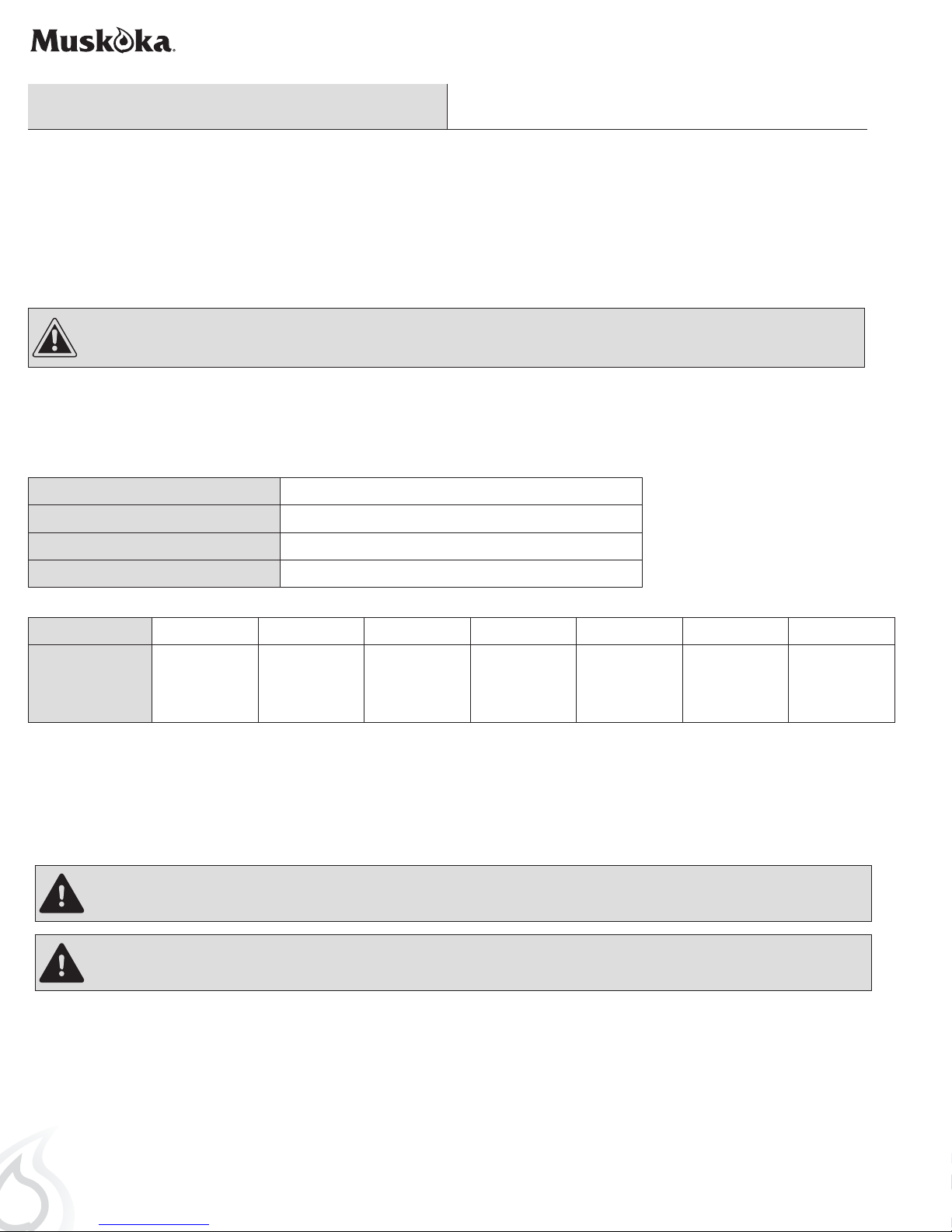
SPECIFICATIONS
Model No.
Wall Mounted Dimensions W x D x H
Stand Mounted Dimensions W x D x H
Net Weight • Gross Weight
Country
Heater Rating
USA Canada Mexico UK Spain Australia Taiwan
120V, 60Hz,
1400 W,
4777 BTUs
MHC35BL
91.5 cm / 36 in x 12.8 cm / 5 in x 44 cm / 17.3 in
91.5 cm / 36 in x 22.2 cm / 8.7 in x 54.1 cm / 21.3 in
14.4 kg / 31.8 lb • 17.9 kg / 39.5 lb
120V, 60Hz,
1400 W,
4777 BTUs
120V, 60Hz,
1400 W,
4777 BTUs
220-240V,
50Hz, 1400 W,
4777 BTUs
220-240V,
50Hz, 1400 W,
4777 BTUs
220-240V,
50Hz, 1400 W,
4777 BTUs
110V, 60Hz,
1200 W,
4094 BTUs
ELECTRICAL CONNECTION
WARNING: Electrical outlet wiring must comply with local building codes and other applicable regulations to reduce the risk of fire, electrical
shock, and injury to persons.
WARNING: Do not use this fireplace if any part of it has been under water. Immediately call a qualified service technician to inspect the
fireplace and replace any part of the electrical system which has been under water.
A properly grounded outlet is required to operate this appliance. Preferably, the appliance will be on a dedicated circuit, as other appliances on
the same circuit may cause the circuit breaker to trip or the fuse to blow when the fireplace is in operation. The unit comes standard with a 1.8
m / 6 ft long 3-wire cord, exiting out the back of the fireplace. Plan the installation to avoid the use of an extension cord. Always plug heaters
directly into a wall outlet/receptacle. Never use with an extension cord or relocatable power tap (outlet/power strip).
4
Pre-Installation (continued)
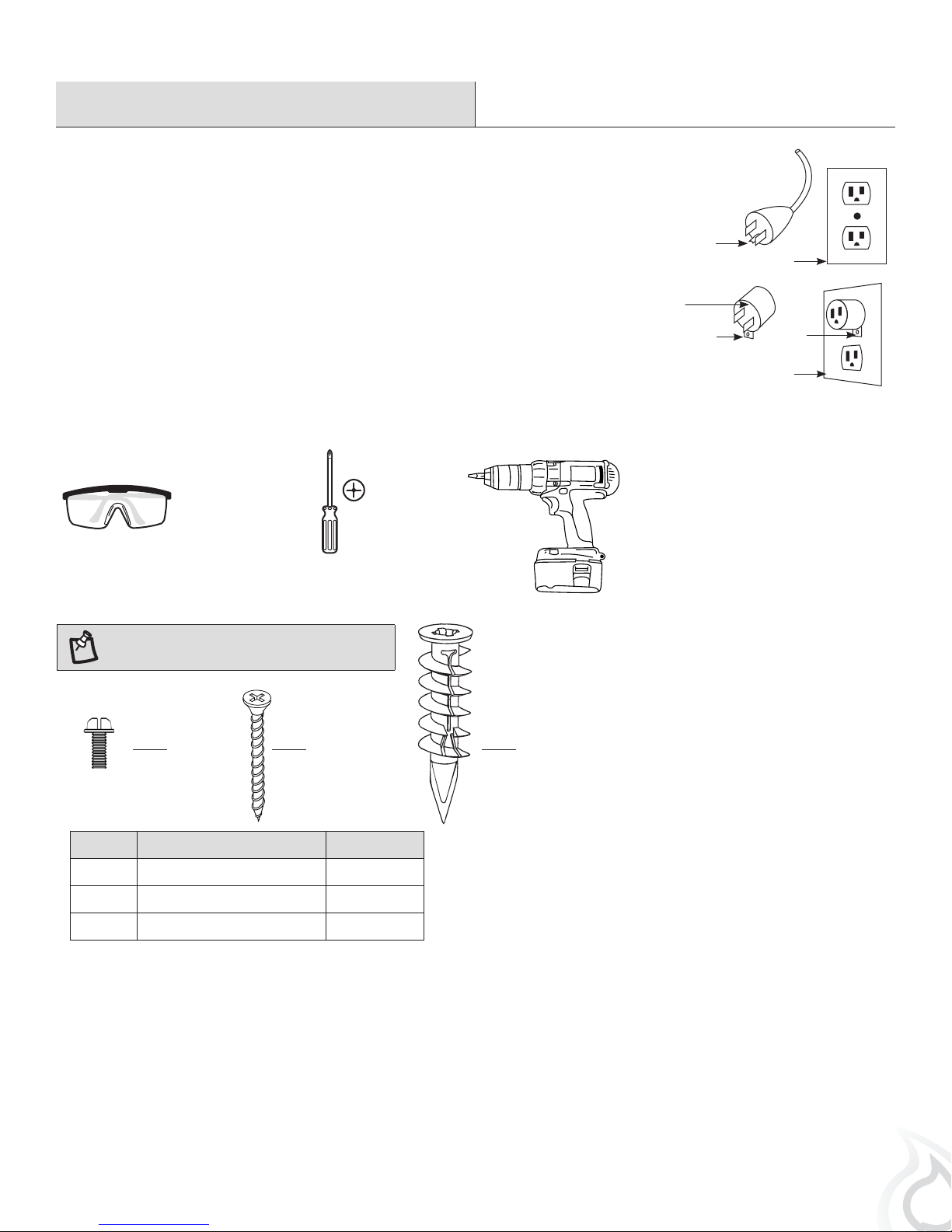
GROUNDING INSTRUCTIONS
This fireplace is for use with 110V/120V/220-240V power sources. The cord has a three-blade,
grounding-type plug. An adapter is available for connecting three-blade grounding-type
plugs to two-slot receptacles. The green grounding lug extending from the adapter must
be connected to a permanent ground, such as a properly grounded outlet box. The adapter
should not be used if a three-slot grounded receptacle is available. (Note: Grounding adapter
use prohibited in Canada)
TOOLS REQUIRED (NOT INCLUDED)
Grounding Pin
Cover of Grounded Outlet Box
Adapter
Grounding Lug
Cover of Grounded Outlet Box
Metal
Screw
Safety goggles
HARDWARE INCLUDED
NOTE: Hardware shown to actual size.
AA
Part Description Quantity
AA Small Screw 12
BB Large Screw 4
CC Wall Anchor 4
BB CC
Phillips
screwdriver
Power drill
5
Pre-Installation (continued)
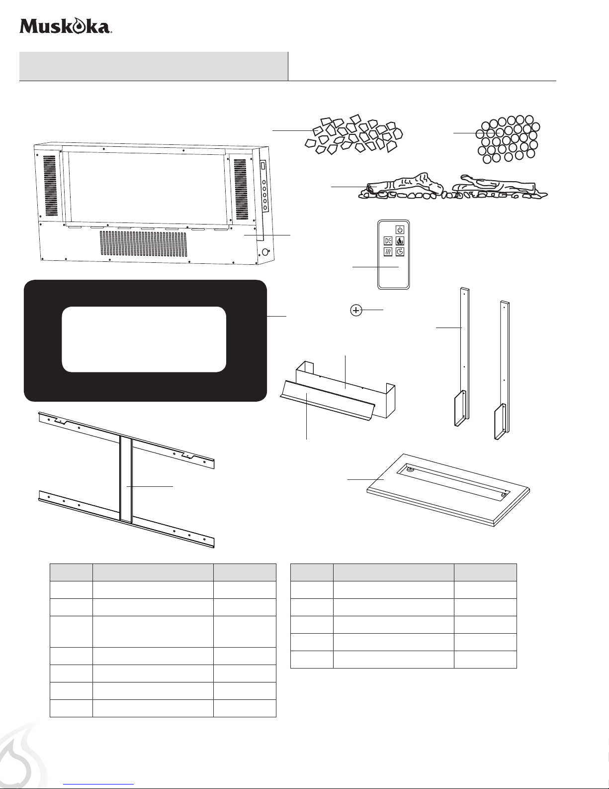
PACKAGE CONTENTS
D
E
F
A
K
B
I
L
G
C
Part Description Quantity
A Electric Firebox 1
B Glass Front 1
C Mounting Bracket (attached
to the Firebox A)
D Acrylic Crystals 1
E Pebbles 1
F Log Set 1
G Table Top Support 2
Note: Both table top supports are identical.
H
J
Part Description Quantity
H Deflector 1
I Front 1
1
J Table Top Base 1
K Remote Control 1
L Battery 1
6
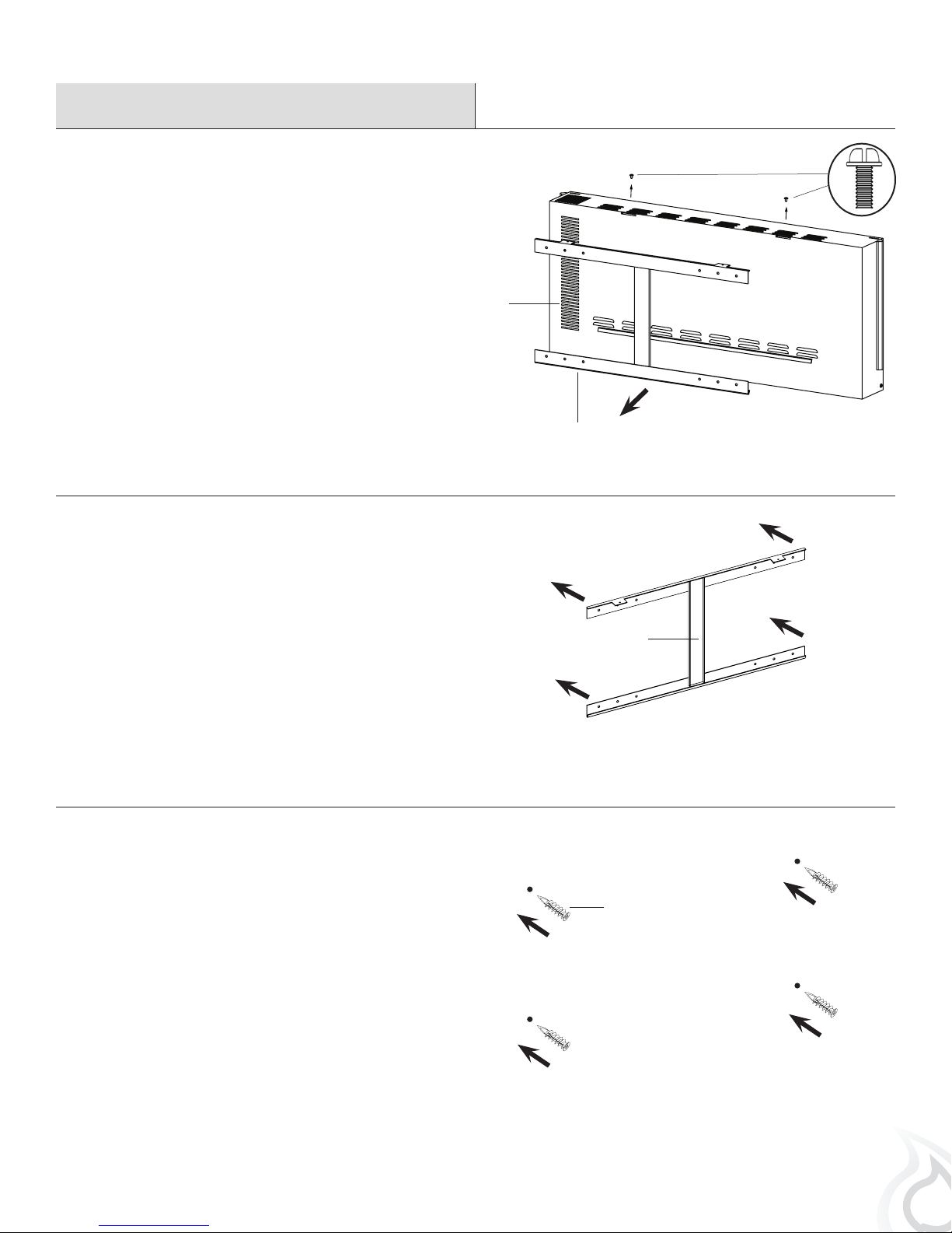
Installation - Wall-Mount
Removing the mounting bracket
1
□ Using a screwdriver, loosen the two screws (AA) that
secure the mounting bracket (C) to the top of the electric
firebox (A), and remove the mounting bracket (C).
Positioning the mounting bracket
2
AA
A
C
□ Choose a solid wall. Position the mounting bracket (C)
where the electric firebox (A) is to be installed on the wall,
and ensure that the mounting bracket (C) is level.
□ Use a pen to mark the 4 mounting holes on the wall at the
desired mounting location, using the mounting bracket (C)
as a template.
Securing the mounting bracket
3
□ Insert the 4 self-drilling wall anchors (CC) into the wall
where previously marked. If installing the mounting
bracket (C) to a wall stud, there is no need to drill the
holes in the wood and no need for the plastic wall anchors
(CC). It is recommended to install the mounting bracket to
at least one stud.
C
CC
7

Installation - Wall-Mount (continued)
Securing the mounting bracket
4
BB
□ Secure the mounting bracket (C) to the wall using four
large screws (BB).
Hanging the electric firebox
5
□ Hang the electric firebox (A) on the hooks at the bottom of
the mounting bracket (C), and push the top of the electric
firebox (A) into the mounting bracket (C).
□ Secure the electric firebox (A) to the mounting bracket
(C) by refitting the two small screws (AA) which were
removed in step 1.
Inserting the ember bed
6
□ Arrange the ember beds (acrylic crystals [D], pebbles [E]
or log set [F] ) along the inset window ledge at the front of
the electric firebox (A).
C
AA
C
A
WALL
D, E, or F
A
Installing the glass front
7
NOTE: This glass front is heavy. It is recommended that you use two
people at this stage to prevent damage to the glass front or the electric
firebox.
□ Lift the glass front (B) into place, making sure the 2 tabs on the top
back of the glass front (B) fit securely into the holes on the top of
the electric firebox (A).
□ Secure the glass front (B) by fastening two small screws (AA) on
both sides.
8
A
WALL
B
AA

Installation - Table Top
Removing the mounting bracket
1
□ Using a screwdriver, loosen the two screws (AA) that
secure the mounting bracket (C) to the top of the electric
firebox (A), and remove the mounting bracket (C).
Assembling the table top stand
2
AA
A
C
□ Attach the left and right table top supports (G) to the table
top base (J) using 4 small screws (AA).
□ Attach the deflector (H) to the front (I) using 2 small
screws (AA). Slide the front assembly onto the table top
supports (G), and onto the base assembly.
H
AA
I
G
J
AA
G
H
I
9

Installation - Table Top (continued)
Securing the mounting bracket
3
□ Use a screwdriver to secure the mounting bracket (C) to
the table top stand with 4 small screws (AA).
Securing the electric firebox
4
□ Using a screwdriver, secure the electric firebox (A) to the
top of the mounting bracket (C) with 2 small screws (AA).
AA
C
AA
C
A
Inserting the ember bed
5
□ Arrange the ember beds (acrylic crystals [D], pebbles [E]
or log set [F] ) along the inset window ledge at the front of
the electric firebox (A).
Installing the glass front
6
NOTE: This glass front is heavy. It is recommended that you use two
people at this stage to prevent damage to the glass front or the electric
firebox.
□ Lift the glass front (B) into place, making sure the 2 tabs on the
top back of the glass fit securely into the holes on the top of the
electric firebox (A).
□ Secure the glass front (B) by fastening two small screws (AA) on
both sides.
D, E, or F
A
B
A
AA
10
STAND
Operation
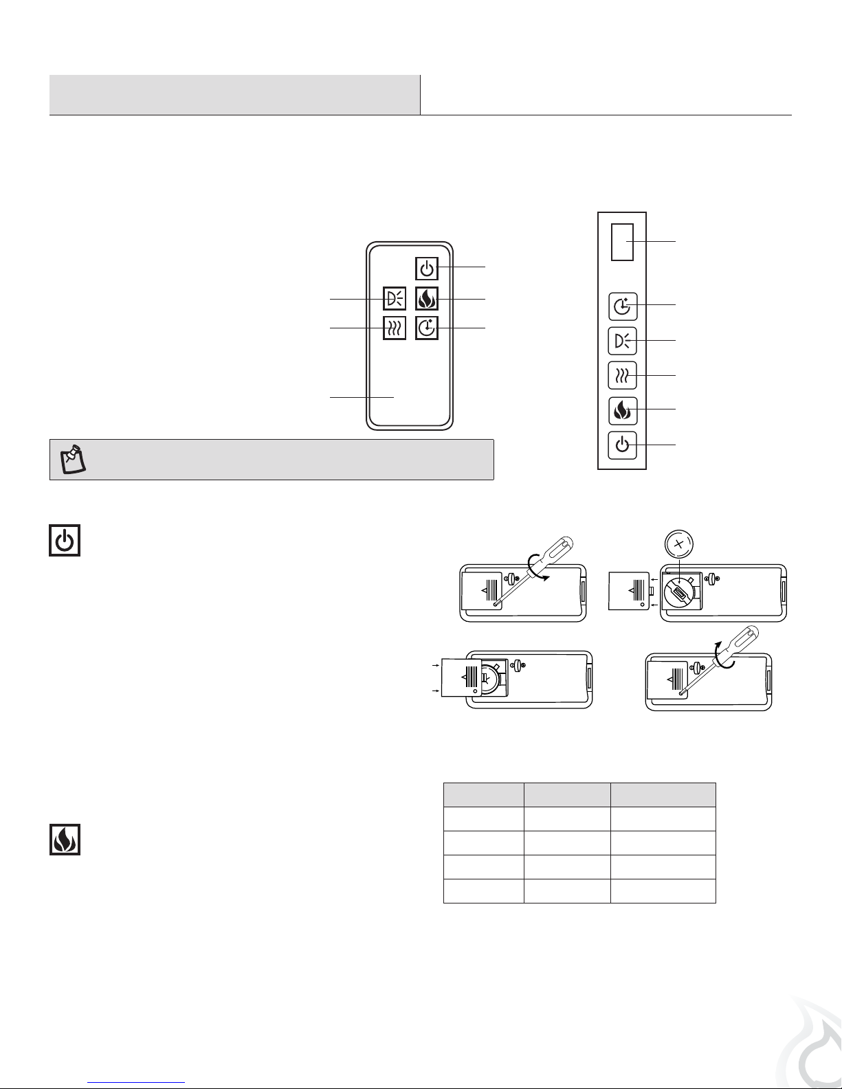
USING THE MANUAL AND REMOTE CONTROLS
On the top-right side plate of the electric fireplace (A) is the control panel. This panel contains the buttons to properly operate the electric
fireplace. The buttons on the control panel on the side of the electric fireplace (A) and the remote control (K) function in the same way. The
remote control has an effective range of up to 3.9 m / 13 ft.
6
1. Power Button
2. Flame Control Button
3. Thermostat Control Button
4. Side Light Control Button
5. Timer Control Button
6. Digital Display Panel
NOTE: The remote control is intended only for the functional operation product,
it cannot lock/unlock the heating function or adjust the temperature setting.
USING THE POWER BUTTON
□ The main power button (1) is located on the control panel
on the side of the electric fireplace.
□ Pressing the power button (1) once turns the power on.
□ Pressing the power button (1) again will turn the power
off.
□ If you find that none of the other buttons appear to work,
check to make sure that the main power (1) is turned on.
4
3
K
1
2
5
BATTERY REPLACEMENT
3 Volt lithium coin cell type 2032
1.
3.
2.
4.
5
4
3
2
1
USING THE FLAME CONTROL BUTTON
□ Press the flame control button (2) to turn on the ember
bed and flame effect.
□ Pressing the flame control button (2) once turns flames on
and lights the ember bed.
□ Pressing the flame control button (2) again will cycle
through different colors of the ember bed. The color
rotation mode will cycle through the 3 different color
settings continuously. Reference the table for more
detailed information.
This product contains a button battery. If swallowed, it could cause severe injury
or death in just 2 hours. Seek medical attention immediately. Please dispose of
the used battery per municipal or provincial/state law.
Button Press Flame State Ember Bed Color
1st Press ON Amber
2nd Press ON Blue
3rd Press ON Amber and Blue
4th Press ON Color Rotation
11

Operation (continued)
USING THE THERMOSTAT CONTROL BUTTON
□ The heat button (3) turns the heater on and off.
□ With the unit ON, press the control panel heat button (3)
for 5 seconds and enter temperature adjustment mode. In
the adjustment mode, the digital indicator (6) will flash.
□ Press the heat button (3) to change to the desired
temperature. There are 10 temperature settings.
Reference the table for more detailed information.
□ After the temperature is selected, the digital display (6)
will stay on for 10 seconds, then turn off.
ADJUSTING THE AMBIENT SIDE LIGHTING
□ Press the side light control button (4) to turn on the
ambient lighting.
□ To change the color of the lighting press the side light
control button (4) again. You can control the side lights
color as described in the table. The color rotation
mode will cycle through the 3 different color settings
continuously.
Display Value Temperature Setting
0 18°C / 64°F
1 19°C / 66°F
2 20°C / 68°F
3 21°C / 70°F
4 22°C / 72°F
5 23°C / 74°F
6 24°C / 76°F
7 25°C / 78°F
8 26°C / 80°F
9 27°C / 82°F
N ON
Button Press Side Light Color
1st Press Blue
2nd Press Amber
3rd Press Amber and Blue
4th Press Color Rotation
5th Press Off
USING THE TIMER CONTROL BUTTON
□ Pressing the timer control button (5) will set the timer.
This interval period is shown in the display (6) on the
control panel on the side of the electric fireplace. The set
intervals are as listed in the table.
NOTE: If this product experiences exceptionally
high temperature, it may automatically stop heating.
If this occurs the product should be unplugged or
isolated from the main supply for a period of 30
seconds before the power is then re-supplied.
NO HEAT FUNCTION (DEMO MODE)
□ To turn off heat mode, press and hold the heat button for 10 seconds to enter heat lock out mode.
□ Ember bed lights will flash 6 times to signal the heat function is turned off and locked out.
10 SEC
□ When the heat button is pressed in lock out mode, the ember bed will flash 6 times until heating mode is turned on
□ To turn on heat mode, press and hold the heat button for 10 seconds, the ember bed will flash 6 times and the heat function will be
restored.
Button Press Timer Interval Display Value
1st Press 1 Hour 1
2nd Press 2 Hour 2
3rd Press 3 Hour 3
4th Press 4 Hour 4
5th Press 5 Hour 5
6th Press 6 Hour 6
7th Press 7 Hour 7
8th Press 8 Hour 8
9th Press OFF NONE
12
 Loading...