

Muskoka 23-800-001, MFB25WSC-1 Use And Care Manual

ELECTRIC FIREBOX FOYER ÉLECTRIQUE HOGAR ELÉCTRICO
USE AND CARE GUIDE | GUIDE D’UTILISATION ET D’ENTRETIEN | GUÍA DE USO Y CUIDADO
IMPORTANT:
SAVE THESE
INSTRUCTIONS.
PLEASE READ THIS MANUAL BEFORE
INSTALLING AND USING APPLIANCE
IF THE INFORMATION IN THIS MANUAL IS NOT FOLLOWED
EXACTLY, AN ELECTRICAL SHOCK OR FIRE MAY RESULT
CAUSING PROPERTY DAMAGE, PERSONAL INJURY OR LOSS OF LIFE.
Retain this manual for future use.
WARNING!
23-800-001
IMPORTANT :
CONSERVER CES
INSTRUCTIONS.
VEUILLEZ LIRE CE MANUEL AVANT L’INSTALLATION
ET L’UTILISATION DE VOTRE FOYER
SI LES RENSEIGNEMENTS DE CE MANUEL NE SONT PAS EXACTEMENT
SUIVIS, UN CHOC ÉLECTRIQUE OU UN INCENDIE PEUT SURVENIR, ET
CAUSER DES DOMMAGES, DES BLESSURES OU LA PERTE DE VIE
Conserver ce manuel pour une utilisation ultérieure.
AVERTISSEMENT!
218326
IMPORTANTE:
GUARDE ESTAS
INSTRUCCIONES.
POR FAVOR LEA LAS INSTRUCCIONES DE
INSTALACIÓN Y DE OPERACIÓN ANTES DE
USAR ESTE CAJA DE FUEGO
SI NO SIGUE EXACTAMENTE LA INFORMACIÓN EN ESTE MANUAL, PODRÍA
RESULTAR EN CHOQUES ELÉCTRICOS O INCENDIO QUE PUEDEN CAUSAR
DAÑOS A LA PROPIEDAD, LESIONES PERSONALES O LA PÉRDIDA DE LA VIDA.
Guarde este manual para futuras referencias.
¡ADVERTENCIA!
Français p. 11 | Español p. 2020-10-242

Table of Contents
Table of Contents ...........................2
Safety Information ...........................2
User Instructions ............................ 3
Grounding Instructions ......................3
Locating Your Fireplace .....................3
Mantel Installation .......................... 3
Firebox Specications ....................... 3
Electrical Connection ....................... 3
Warranty ...................................4
Pre-Installation ..............................5
Planning Installation ........................ 5
Tools Required. . . . . . . . . . . . . . . . . . . . . . . . . . . . . 5
Hardware Included ........................5
Package Contents .........................5
Installation .................................6
Operation. . . . . . . . . . . . . . . . . . . . . . . . . . . . . . . . . . 6
Maintenance ............................... 7
Glass information ..........................7
Maintenance of Motors .....................7
Replacing the Light Bulbs .................... 7
Battery Replacement ....................... 8
Circuit Diagram ............................. 8
Care and Cleaning. . . . . . . . . . . . . . . . . . . . . . . . . . 8
Troubleshooting ............................. 9
Service Parts ...............................10
Safety Information
1. Read all instructions before using this heater.
2. This heater is hot when in use. To avoid burns, do not let bare skin touch hot surfaces. If provided, use
handles when moving this heater. Keep combustible materials, such as furniture, pillows, bedding, papers,
clothes, and curtains at least 3 feet (0.9 meters) from the front of the heater and keep them away from the
sides and rear.
3. Extreme caution is necessary when any heater is used by or near children or invalids and whenever the
heater is left operating and unattended.
4. Always unplug heater when not in use.
5. Do not operate any heater with a damaged cord or plug or after the heater malfunctions, has been
dropped or damaged in any manner. Return heater to authorized service facility for examination,
electrical or mechanical adjustment, or repair.
6. Do not use outdoors.
7. This heater is not intended for use in bathrooms, laundry areas and similar indoor locations. Never locate
heater where it may fall into a bathtub or other water container.
8. Do not run power cord under carpeting. Do not cover power cord with throw rugs, runners, or the like.
Arrange power cord away from trafc area and where it will not be tripped over.
9. To disconnect heater, turn controls to off, then remove plug from outlet.
10. Connect to properly grounded outlets only.
11. Do not insert or allow foreign objects to enter any ventilation or exhaust openings as this may cause an
electric shock or re, or damage the heater.
12. To prevent a possible re, do not block rebox air intakes or exhaust in any manner. Do not operate rebox
on soft surfaces, like a bed, where openings may become blocked.
13. A heater has hot and arching or sparking parts inside. Do not use in areas where gasoline, paint, or
ammable liquids are used or stored.
14. Use this heater only as described in this manual. Any other use not recommended by the manufacturer
may cause re, electrical shock, or injury to persons.
15. Always plug heaters directly into a wall outlet/receptacle. Never use with an extension cord or relocatable
power tap (outlet/power strip).
16. This electric replace is not designed for “zero” clearance wall and/or cabinet/millwork installations.
Accessibility for servicing and maintenance must be possible without disturbing building structures and/or
cabinet/millwork nishes.
17. SAVE THESE INSTRUCTIONS
2
Safety Information (continued)
USER INSTRUCTIONS
1. Any repairs to this appliance should be carried out by qualied/authorized service personnel only.
2. Under no circumstances should this appliance be modied. Parts having to be removed for servicing must
be replaced with original “OEM” (original equipment manufacturers) parts only.
3. This rebox is to be cleaned with a damp cloth (water) only.
IMPORTANT: Always unplug the power cord before cleaning the unit. Do not use any abrasive cleaners on
the unit.
4. Unplug this rebox when not in use.
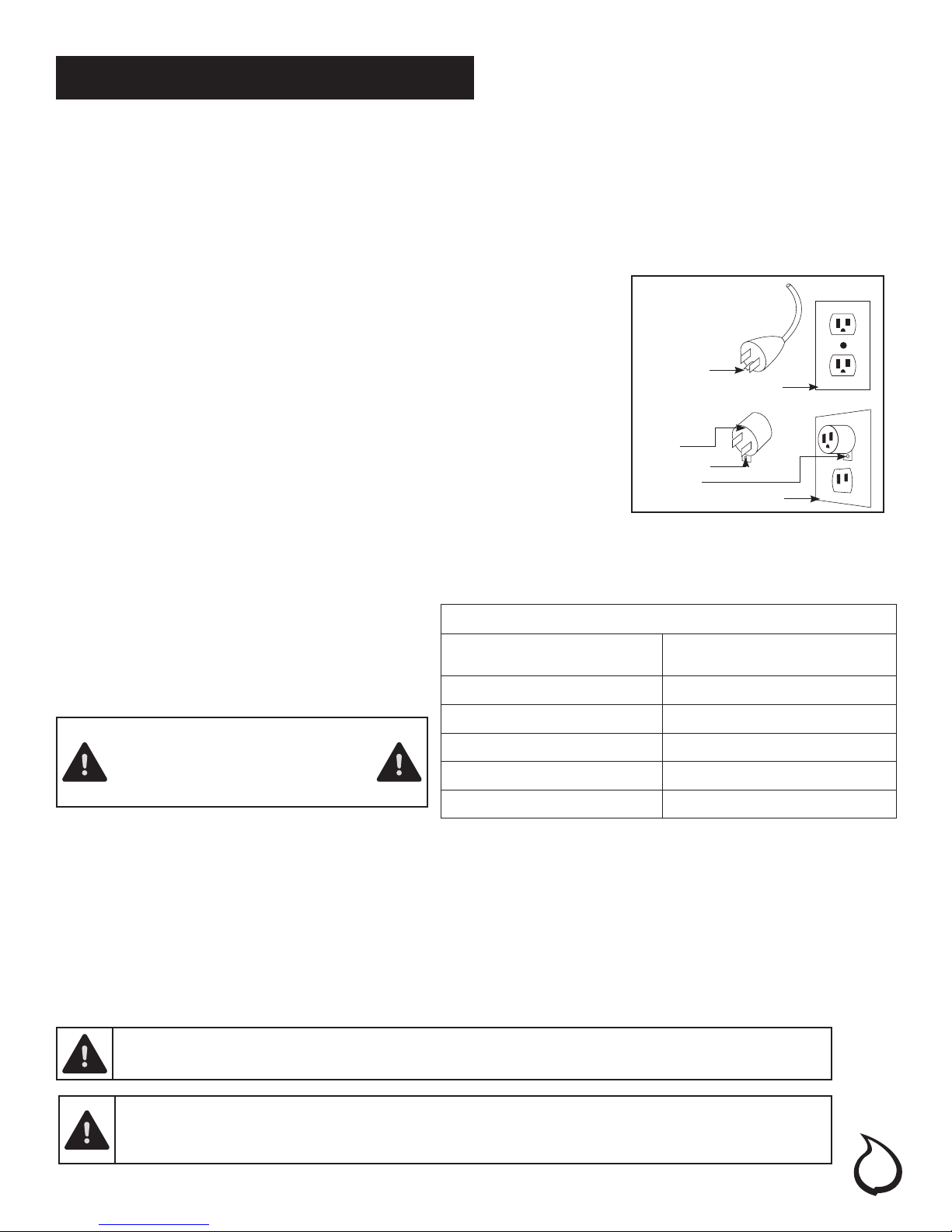
GROUNDING INSTRUCTIONS
A
This heater is for use on 120 volts. The cord has a plug as shown in gure
1A in the diagram. An adapter as shown in gure 1C is available for
Grounding Pin
Cover of Grounded Outlet Box
connecting three-blade grounding-type plugs to two-slot receptacles. The
green grounding lug extending from the adapter must be connected to a
permanent ground such as a properly grounded outlet box. The adapter
should not be used if a three-slot grounded receptacle is available.
(Note: Grounding adapter use prohibited in Canada)
Adapter
Grounding Lug
Metal Screw
Cover of Grounded Outlet Box
C
LOCATING YOUR FIREPLACE
When choosing a location for your new replace, ensure the general instructions are followed. Also, for best
effect install the replace out of direct sunlight. It is safe to set the replace insert close to non-combustibles.
MANTEL INSTALLATION
Please refer to the detailed instructions that
came with the mantel that you purchased.
DO NOT STORE OR USE GASOLINE
OR OTHER FLAMMABLE VAPORS
OR LIQUIDS IN THE VICINITY OF
THIS OR ANY OTHER APPLIANCE.
Fireplace Insert dimensions
(w x d x h)
23-800-001 SPECIFICATIONS
24.25” x 13.4” x 20.25”
61.6 cm x 23.9 cm x 51.4 cm
Net Weight 27.7 lbs • 12.6 kg
Voltage 120 V
Frequency 60 Hz
Watts • Amps. 1350W • 12.5A
Heater Rating 4777 BTU's
B
A 15 Amp, 120 Volt, 60 Hz circuit with a properly grounded outlet is required to operate this appliance.
Preferably, the replace insert will be on a dedicated circuit as other appliances on the same circuit may
cause the circuit breaker to trip or the fuse to blow when the heater is in operation. The unit comes standard
with a 6 ft (1.8 m) long 3 wire cord, exiting out the back of the replace insert. Plan the installation to avoid the
use of an extension cord. If an extension cord must be used, it must be a minimum 14 ga, 3 wire with grounding
type plug and connector and rated not less than 1875 watts. The extension cord shall not be more than 20 ft (6
WARNING: Electrical outlet wiring must comply with local building codes and other applicable
regulations to reduce the risk of re, electrical shock and injury to persons.
WARNING: Do not use this replace if any part of it has been under water. Immediately call a qualied
service technician to inspect the replace and replace any part of the electrical system which has
been under water.
ELECTRICAL CONNECTION
m) in length.
3

1 Year Warranty
WHAT IS COVERED
The manufacturer warrants that your new electric replace is free from manufacturing and material defects for
a period of one year from date of purchase, subject to the following conditions and limitations.
This electric replace must be installed and operated at all times in accordance with the instructions furnished
with the product. Any alteration, willful abuse, accident, or misuse of the product shall nullify this warranty.
This warranty is non-transferrable, and is made to the original owner, provided that the purchase was made
through an authorized supplier of the manufacturer.This warranty is limited to the repair or replacement of
part(s) found to be defective in material or workmanship, provided that such part(s) have been subjected
to normal conditions of use and service, after said defect is conrmed by the manufacturer’s inspection. The
manufacturer may, at its discretion, fully discharge all obligations with respect to this warranty by refunding the
wholesale price of the defective part(s).
WHAT IS NOT COVERED
Any installation, labor, construction, transportation, or other related costs/expenses arising from defective
part(s), repair, replacement, or otherwise of same, will not be covered by this warranty, nor shall the
manufacturer assume responsibility for same. Further, the manufacturer will not be responsible for any
incidental, indirect, or consequential damages, except as provided by law.
All other warranties - expressed or implied - with respect to the product, its components and accessories, or any
obligations/liabilities on the part of the manufacturer are hereby expressly excluded. The manufacturer neither
assumes, nor authorizes any third party to assume, on its behalf, any other liabilities with respect to the sale of
this product. The warranties as outlined within this document do not apply to nonmanufacturer accessories
used in conjunction with the installation of this product.
This warranty does not cover the light bulb(s) included with the replace.
This warranty is void if: the replace has been operated in atmospheres contaminated by chlorine, uorine, or
other damaging chemicals; the replace is subjected to prolonged periods of dampness or condensation; the
replace is altered, willfully abused, damaged by accident, or misused in any way.
Make sure you have your warranty, your sales receipt, and the model/serial number of your product.
DO NOT ATTEMPT TO DO ANY SERVICE WORK YOURSELF. PLEASE CONTACT CUSTOMER SERVICE AT:
1-866-253-0447 Monday to Thursday from 8:30AM to 5:00PM (EST),
Friday from 8:30AM to 4:00PM (EST)
Web: www.greenwayhp.com
Email: support@greenwayhp.com
Canada: 400 Southgate Dr., Guelph, Ontario, Canada, N1G 4P5
USA: 6440 W. Howard Street, Niles, Illinois U.S.A. 60714
4
Pre-Installation
PLANNING INSTALLATION
To avoid scratching the nish, assemble the product on a soft, non-abrasive surface, such as carpet or
cardboard.
Assembly of this product may require more than one person.
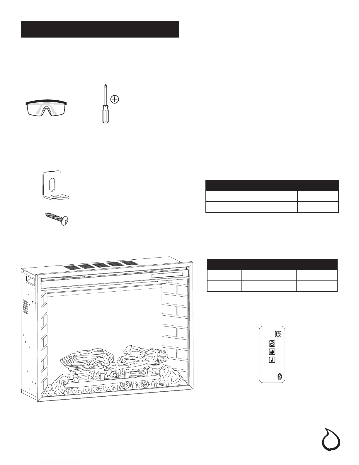
TOOLS REQUIRED
Safety Goggles Phillips screwdriver
HARWARE INCLUDED
Note: Hardware not shown to actual size.
AA
BB
PACKAGE CONTENTS
PART DESCRIPTION QUANTITY
AA Mounting Bracket 2
BB Screw (ST4) 4
PART DESCRIPTION QUANTITY
A Fireplace Insert 1
B Remote Control 1
A
JY-3B
B
5
Preparation
Before beginning assembly of product, make sure all parts are present. Compare parts with package contents
list and hardware contents. If any part is missing or damaged, do not attempt to
assemble the product. Contact customer service for replacement parts.
Estimated Assembly Time: 15 minutes
Phillips Screwdriver (not included)
Open the unit and check carefully for visible damage. If you have any problems with installation,
operation, missing parts, or damage,please call 877-447-4768 for service.
DO NOT dispose of packaging until you are satised with your replace.
DO NOT return unit to store before calling 877-447-4768 for service.
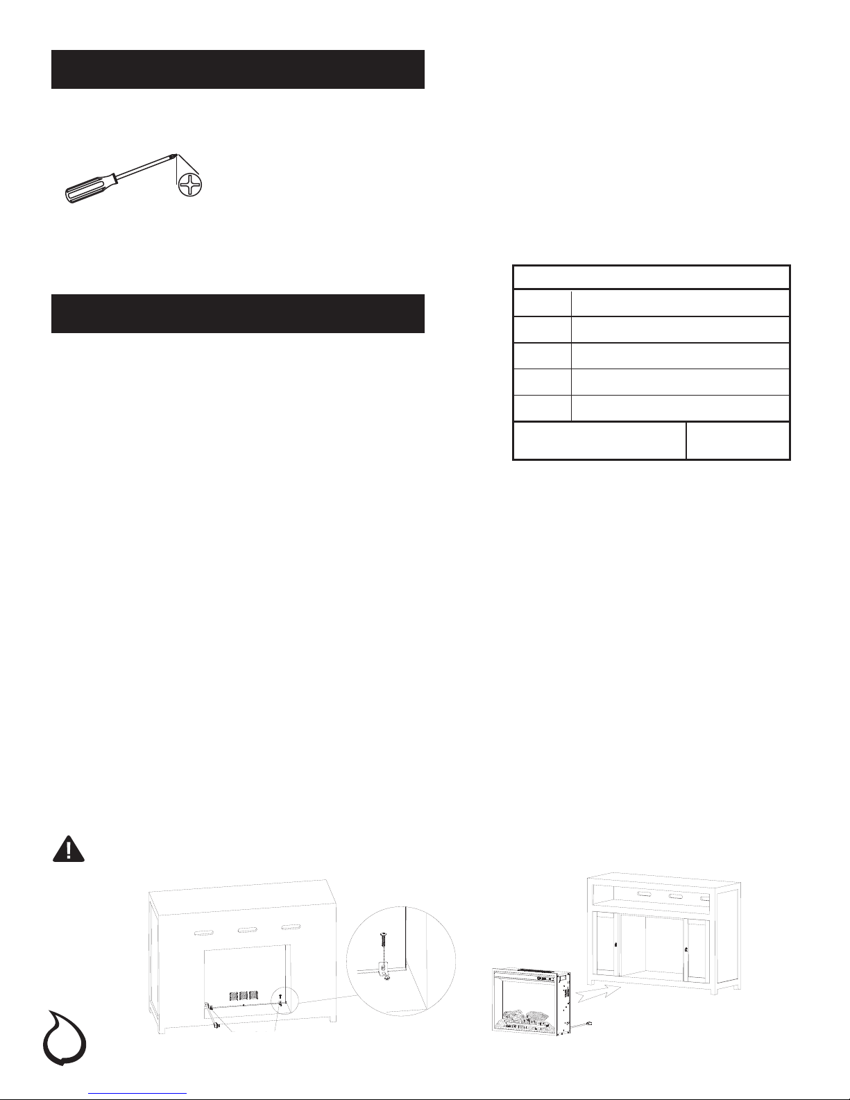
Clearance to Combustibles
Installation
Sides 2-27/64 in. (61.5 mm)
Floor 0 in. (0 mm)
The Fireplace should be located in an area:
• Out of direct sunlight
• Not susceptible to moisture
• Away from uninsulated outside wall
• At least 3 ft. (.9 m) from drapery, furniture and other combustibles
1. Place the assembled mantel near a 15-amp, 120-volt grounded electric outlet.
Read all instructions before using this appliance.
2. Place the insert directly in front of the mantel opening.
3. Carefully lift the insert through the center opening in the front of the replace. The bottom of the insert has
two foam rubber strips to prevent scratching of the hearth base. Slide the insert back through the opening
until the metal trim makes contact with the front of the mantel.
4. Install the mounting brackets provided with the insert in the pre-drilled holes on the bottom of the
insert (see Figure 2).
5. Carefully position mantel with installed replace against wall.
6. Plug the power cord into the 15-amp, 120-volt outlet. Use an extension cord rated for a minimum of 1,875
watts if necessary.
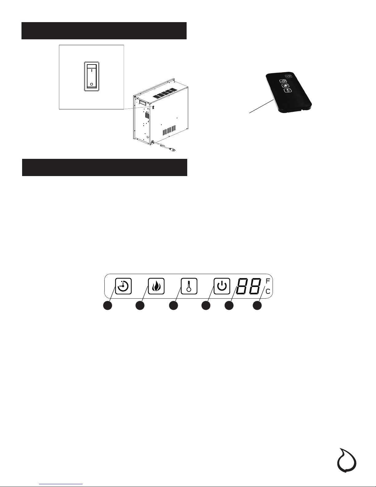
NOTE: This unit comes equipped with a safety switch on the back panel which disables the heater (See Figure 3).
To enable the heater, please ensure the switch is in the “On” mode. The heater will function using the remote
control or control panel on the front of the unit.
NOTE: This unit comes equipped with a safety switch on the back panel which disables the heater (See Figure 3).
To enable the heater, please ensure the switch is in the “On” mode. The heater will function using the remote control
or control panel on the front of the unit.
Top 2 in. (51 mm)
Front 36 in. (914 mm)
Rear 25/32 in. (20 mm)
Wooden Facing 5/16 in. (8 mm)
[up to 5/8 in. (16 mm) thick]
CAUTION: Make sure that the unit is installed so that the power cord is not compressed against or caught on
the unit or the mantel and that it has an unobstructed path to the grounded outlet.
Figure 2
6
Mounting Brackets
Installation (Continued)
Figure 3
Enable Heater/Calefacción habilitada/
Chauffage activé
Disable Heater/Calefacción deshabilitada/
Chauffage désactivé
Infrared Remote Control
Operating Instructions
The replace control functions can be accessed in two (2) ways:
• Using the touchpad control panel, located in the upper right-hand corner of the replace behind the sliding
control panel cover.
• Using the multifunction remote control unit.
The replace features conveniently separate controls for ame effect and for heater control. This allows you to
operate the unit in two (2) different modes:
• As a full-featured replace - both ame effect and heater are on.This mode allows you to enjoy the look of
the re along with the heat output of a heater.
• As a visual effect - only the ame effect is on, the heater is off. We recommend this mode for warm weather
application, when you want the ambiance of a re, without any heat output.
Figure 4
1. Main Power Button:
This button supplies power to all the functions of the replace. The Main Power button must be in the ON position, either from the remote or on the touch pad for the functions to work.
2. Heater Control Button:
This button controls the heater ON/OFF and 11 temperature modes from 68°F (20°C) to 88°F (31°C). When the
heater is rst turned on, it will come on at the lowest room temperature setting 68°F (20°C). Each time the
Heater Control button is pressed, the temperature set point increases 2°F (1°C), allowing you to adjust the
ambient temperature, up to 88°F (31°C). The replace will remember the last heat setting, and in later use, the
heater will start at that setting, unless power to the unit has been interrupted.
3. Flame Control button:
This button controls the brightness of the ame effect with settings at High, Medium and Low. When the replace is rst turned on, the ame will come on at the highest setting. The replace will remember the last ame
setting used and in later use the ame brightness will start at that setting, unless power to the unit has been
interrupted. Each time the Flame button is pressed, the ame brightness decreases. The only way to turn off the
ame effect completely is to turn off the Main Power button.
4. Timer Button:
This button controls the timer ON/OFF and 10-time setting from 30 minutes to 9 hours. When the Timer is rst
turned on, it will come on at the shortest time setting (30 minutes). Each time the Timer button is pressed, the
time increases 1 hour, up to the longest setting (9 hours). Once the set time expires, all replace functions will be
automatically turned off.
1 6 5234
7
Operating Instructions (Continued)
5. Fahrenheit/Celsius Display:
This button displays F (Fahrenheit) or C (Celsius) depending on how the temperature mode is set. When the
replace is rst turned on, the Fahrenheit (F) temperature will be displayed. To switch from Fahrenheit to Celsius,
or vise-versa, when HEATER is ON, hold HEATER CONTROL button for 10 seconds. The replace will remember the
last temperature mode setting, and in later use, the display will start at that setting, unless power to the unit has
been interrupted.
6. Temperature/Timer Display
This LED display shows the set point for the temperature and timer functions. When either of these functions is
activated, the display reects the set point for ve seconds and then fades to black. Any change in the set
point of the temperature or timer will reactivate the display, which again fades after ve seconds.
The infrared remote control relies on a line of sight and must be pointed at the ame/screen of the replace to
work. The remote control unit has the controls required to turn ON/OFF both the main power and the heater.
If you prefer to use the touchpad control on the replace unit itself, open the control panel sliding cover to
access the touchpad buttons.The layout of the buttons on touchpads and remote control unit can be seen in
Figures 4 and 6, respectively.
1. Plug your replace into a 15-amp, 120-volt power outlet.
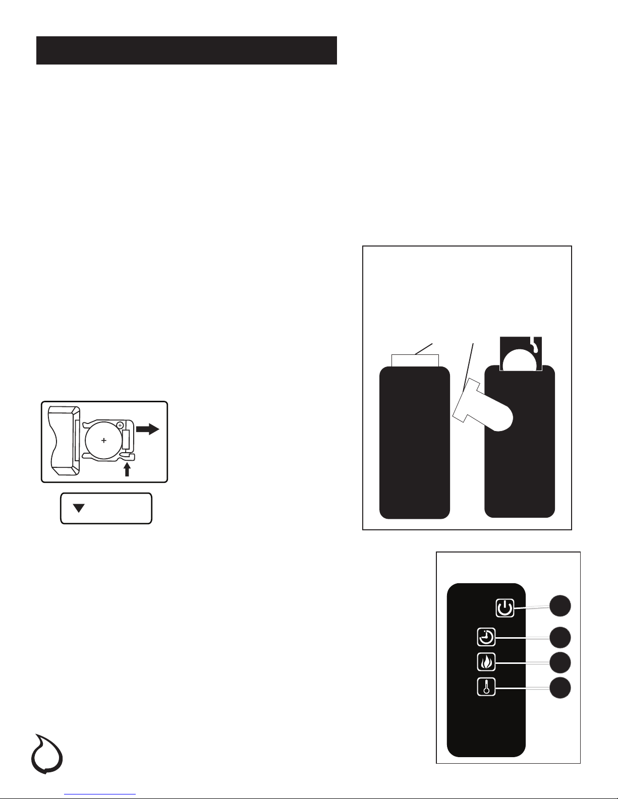
2. Turn the power on. Flame will show on the back screen of the
replace.
3. Remove plastic tab from inside battery compartment
to activate remote control.
4. Point the remote control directly at the replace
ame/screen and use the buttons to operate the
replace.
Figure 5
The plastic tab inside the battery
compartment MUST be removed
before remote control will operate.
(Pull tab)
Battery Replacement Procedure:
Battery replacement instruction
Instructions de remplacement des piles
Instrucción de reemplazo de la batería
CR2025
OPEN
OUVRIR
PUSH
POUSSER
EMPUJE
ABRIR
(Size CR2025)
RELEASE
RELÂCHER
LIBERAR
1. Main Power Button:
This button supplies power to all the functions of the replace. The main power
button must be in the ON position, either from the remote or on the touch pad
for the functions to work.
2. Timer Button:
This button controls the timer ON/OFF and 10-time setting from 30 minutes to 9
hours. When the Timer is rst turned on, it will come on at the shortest time setting
(30 minutes). Each time the Timer button is pressed, the time increases 1 hour, up
to the longest setting (9 hours). Once the set time expires, all replace functions
will be automatically turned off.
Figure 6
1
2
3. Flame Control button:
This button controls the brightness of the ame effect with settings at High,
Medium and Low. When the replace is rst turned on, the ame will come on
at the highest setting. The replace will remember the last ame setting used
and in later use the ame brightness will start at that setting, unless power to
the unit has been interrupted. Each time the Flame button is pressed, the ame
brightness decreases. The only way to turn off the ame effect completely
is to turn off the Main Power button.
8
3
4

Operating Instructions (Continued)
4. Heater Control Button:
This button controls the heater ON/OFF and 11 temperature modes from 68°F (20°C) to 88°F (31°C). When the
heater is rst turned on, it will come on at the lowest room temperature setting 68°F (20°C). Each time the Heater Control button is pressed, the temperature set point increases 2°F (1°C), allowing you to adjust the ambient
temperature, up to 88°F (31°C). The replace will remember the last heat setting, and in later use, the heater will
start at that setting, unless power to the unit has been interrupted.
NOTE: To switch between Fahrenheit/Celsius modes see
control panel Fahrenheit/Celsius display instructions.
Maintenance
DANGER: Disconnect power before servicing.
WARNING: Any electrical re-wiring of this appliance must be done by a qualied electrician. This
wiring must be done in accordance with local codes and/or in Canada with the current CSA C22.1
Canadian Electrical Code, and for US installations, the National Electrical Code ANSI/NFPA NO 70.
WARNING: If repairing or replacing any electrical component or wiring, the original wire routing, color
coding and securing locations must be followed.
GLASS INFORMATION
1. Under no circumstances should this product be operated with a broken or chipped glass panel.
2. Do not strike or slam the glass.
3. Do not use abrasive cleansers to clean the glass. Make sure the glass is cool to the touch.
4. This product uses tempered glass. Replacement of the glass supplied by the manufacturer should be done
by qualied/authorized service personnel only.
MAINTENANCE OF MOTORS
1. Always disconnect the appliance from the main power supply and allow it to cool before any servicing
operation.
2. The motors used on the fan heater and ame blower are pre-lubricated for extended bearing life and
require no further lubrication. However, periodic cleaning/vacuuming of the appliance around the air
intake and exhaust, as well as the fan heater is reccomended. For heavy or continous use, periodic
cleaning must be done more frequently. If the heater blows alternating cold and warm air, check the fan
for free movement and for debris restricting air ow. If the fan does not move freely, the unit be turned off
and fan replaced immiediately in order to prevent further damage to the unit.
Care and Cleaning
1. Always turn the heater OFF and unplug the power cord from the outlet before cleaning.
2. Cleaning of the control panel, located in the upper right-hand corner of the replace is to be done only
using a soft cloth, slightly dampened in water (if needed, a small amount of dish soap can be added to
the water) and dried using a clean, dry soft cloth. Cleaning of the screen diffuser is to be done using only
water and lint free cloth. DO NOT use any abrasive on the controls or the diffusing screen.
9
 Loading...