

Muskoka MEF2803CCHB Assembly Instructions Manual

Electric FireplaceElectric Fireplace
Electric fireplace mantel with
corner option and 28” electric firebox
Foyer Électrique
Manteau pour foyer électrique avec option
de coin et un foyer électrique de 28”
Chimenea Eléctrica
Mueble de chimenea con opción de esquina
y caja de fuego eléctrica de 28”
SAVE THESE INSTRUCTIONS
CONSERVER CES INSTRUCTIONS
GUARDE ESTAS INSTRUCCIONES
MEF2803CCHB
A
W
R
E
R
M
A
O
H
N
I
N
A
R
A
G
A
Í
T
N
A
R
A
G
11
N
T
Y
L
À
A
E
M
I
T
A
I
S
O
N
U
S
N
E
YEAR
AN
AÑO
P
R
O
P
I
A
C
A
S
A
REV07-20
Assembly Instructions
Instructions d’assemblage
Instrucciones de montaje
TIPS FOR THE ASSEMBLY OF YOUR NEW MANTEL
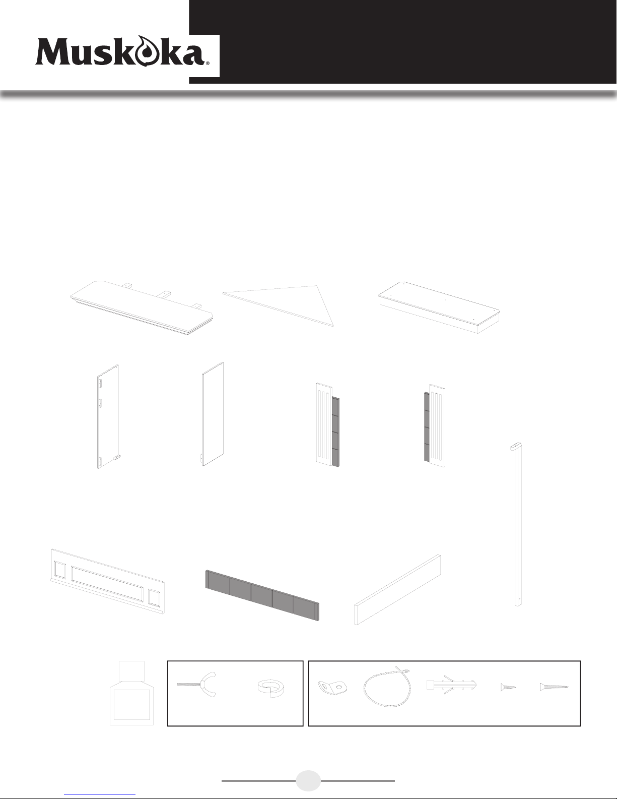
Before you begin assembly, locate the instructions and hardware. Take out all the parts and compare
them to the diagrams below. Be sure you have all the parts and can identify them.
A helping hand is always good. Assemble your mantel with an adult assistant if possible. Some pieces
are heavy and will need to be held by a helper. Assembly time will take approximately 30-60 minutes.
TOP 1PC
ZZ.2803CCHB.08
LEFT SIDE PANEL 1PC
ZZ.2803CCHB.03
CORNER ATTACHMENT 1PC
RIGHT SIDE PANEL 1PC
ZZ.2803CCHB.02
ZZ.2803CCHB.08-1
LEFT FRONT PANEL 1PC
ZZ.2803CCHB.05
BASE 1PC
ZZ.2803CCHB.01
RIGHT FRONT PANEL 1PC
ZZ.2803CCHB.04
CENTRAL HEADER 1PC
ZZ.2803CCHB.06
TOUCH UP
PAINT
INCLUDES 1 SPARE
UPPER FACING 1PC
ZZ.2803CCHB.07
CORNER BOTTOM
SUPPORT 1PC
ZZ.2803CCHB.09
4PCS 2PCS 2PCS 2PCS 2PCS25PCS 25PCS
CORNER UPRIGHT
SUPPORT 1PC
ZZ.2803CCHB.10
ANTI-TIP DEVICE 2 SETSWINGNUT AND LOCK WASHER
1
GET READY TO START
Before assembly, use scissors to unwrap the parts from the packaging.
DO NOT use a box cutter or exacto-knife as you may cut into the
mantel pieces inside the box and damage the fi nish. Check for the
hardware bag which is red and located inside the packaging, taped
to the top box. Be sure you DO NOT discard any pieces.
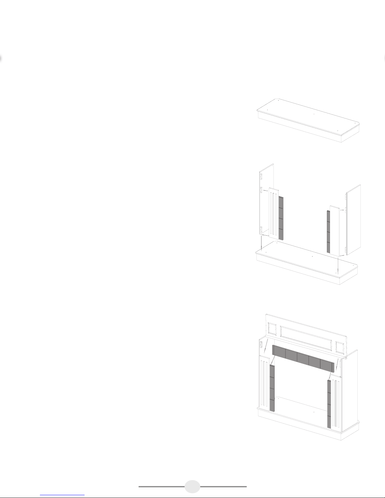
Step 1
Locate the base and place it on the fl oor. Do not put it up against the
wall at this point in the assembly, as you need to get in behind the
mantel to insert several wingnuts, lock washers and fi rebox screws.
Step 2
Locate the left side panel and the left front panel. Facing the front
of the base, take the left side panel, positioning it so the holes in
the blocks on the bottom line up with the holes on the base. Position
the left front panel next to the left side panel, lining up the holes in
the blocks with the holes on the base. Attach the left front and side
panels to the base by inserting and tightening 1 wingnut and 1 lock
washer into each of the 2 blocks. Attach the left side and front panels
together by inserting and tightening 3 wingnuts and 3 lock washers
through the holes in the 3 blocks.
Step 3
Step 1
Step 2 & 3
Repeat Step 2, but with the right side panel and the right front panel.
Step 4
Locate the brick upper facing panel that will be attached to the left
and right legs and will sit above the fi rebox. Position this panel with
the brick side facing the front of the mantel. Line up the holes on each
side and insert and tighten 1 wingnut and 1 lock washer on each
side.
Step 5
Locate the central header that will be attached to the left and right
legs and will sit above the upper facing panel. Position this panel
with the fi nished side facing the front of the mantel. Line up the holes
on each side and insert and tighten 2 wingnuts and 2 lock washers
on each side. Attach the upper facing panel to the central header by
lining up the holes in the center of each part into the hole. Insert and
tighten 1 wingnut and 1 lockwasher.
Step 4 & 5
2
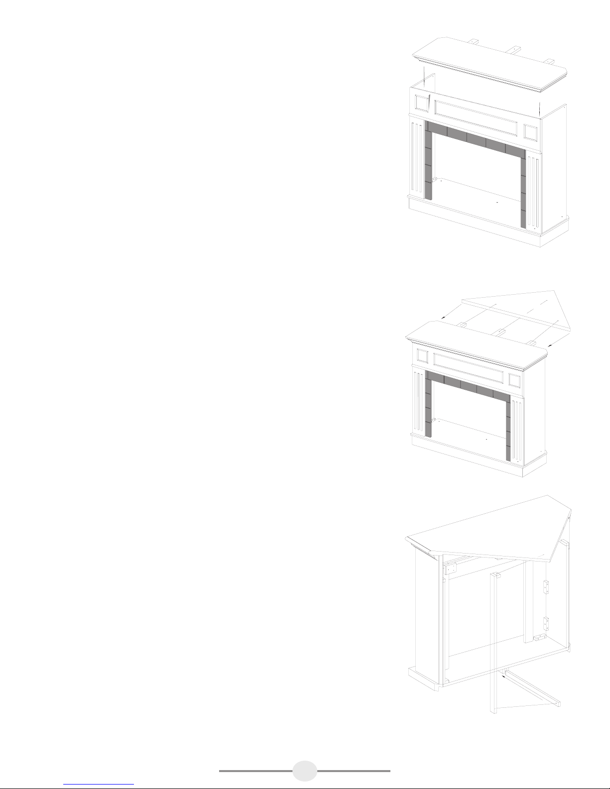
Step 6
Get your assistant and locate the top of your mantel. This top is very
heavy, it will take 2 people to lift and position it in place. Ensure
the top goes over the positioning guide located on the header. The
top must go over this guide to be positioned correctly. Line up the
holes on the top of the mantel, insert and tighten 5 wingnuts and 5
lockwashers.
Step 6
Step 7
If you are using this mantel in a corner application, locate the triangular
piece of wood which attaches to the mantel to create the corner unit.
You must attach this piece for all corner applications. Slide the corner
bottom support into the channel located at the middle of the back of
the hearth base. Place the top corner attachment on the floor upside
down. Protect it from damage. Attach the corner upright support to the
corner attachment by lining up the hole in the corner upright with hole
in the corner top then insert 1 wingnut and 1 lock washer through the
holes in the block and tighten. Simply take the triangle and slide the
brackets with the holes onto the pins which are already attached to
the mantel. Once the triangle is attached, push it up so it is level with
the mantel and lock it into place. To lock it into place simply turn the
3 horizontal wooden blocks attached to the underside of the mantel
into a vertical position to support the weight of the corner triangle.
Insert and tighten 1 wingnut and 1 lock washer into each block. Now
attach the corner bottom support to the corner upright support by
insert and tightening 1 wingnut and 1 lock washer through the holes
at the end of each piece.
Step 7
3

Step 8
Take your electric firebox out of its packaging and position it between
the 2 legs of the mantel. Once you are close to the wall, plug the
firebox into the nearest outlet.
The firebox comes with 3 metal brackets and 16 black screws (15
required plus 1 spare). These metal brackets must be attached to all
3 sides of the firebox and 2 sides of the mantel to ensure that your
firebox does not move around as you use it. All 3 trims attach to
the firebox by inserting and tightening 3 screws. Both the left and
right side trim attach to the mantel front by inserting and tightening
3 screws
The top trim does not attach to the mantel, just the firebox. if you
have any questions about the firebox please reference the installation
instructions that come with the firebox.
Step 8
4
TOP 1PC
LEFT FRONT PANEL 1PC
UPPER FACING 1PC
CORNER ATTACHMENT 1PC
CORNER UPRIGHT SUPPORT 1PC
FIREBOX SHELF 1PC
1225
1165
694
594
925
376
1054
2009-MEF2822CWG-1
TOP 1PC
STEP 1
STEP 2
STEP 3
RIGHT SIDE PANEL 1PC
LEFT SIDE PANEL 1PC
LEFT FRONT PANEL 1PC
UPPER FACING 1PC
CORNER ATTA CHMENT 1PC
CORNER UPRIGHT SUPPORT 1PC
FIREBOX SHELF 1PC
1165
694
594
376
STEP 1
STEP 2
UPPER FACING 1PC
CORNER ATTACHMENT 1PC
FIREBOX SHELF 1PC
4PCS
WING NUT(5*28) 25PCS
STEP 1
STEP 2
UPPER FACING 1PC
CORNER ATTACHMENT 1PC
FIREBOX SHELF 1PC
STEP 1
STEP 2
STEP 3
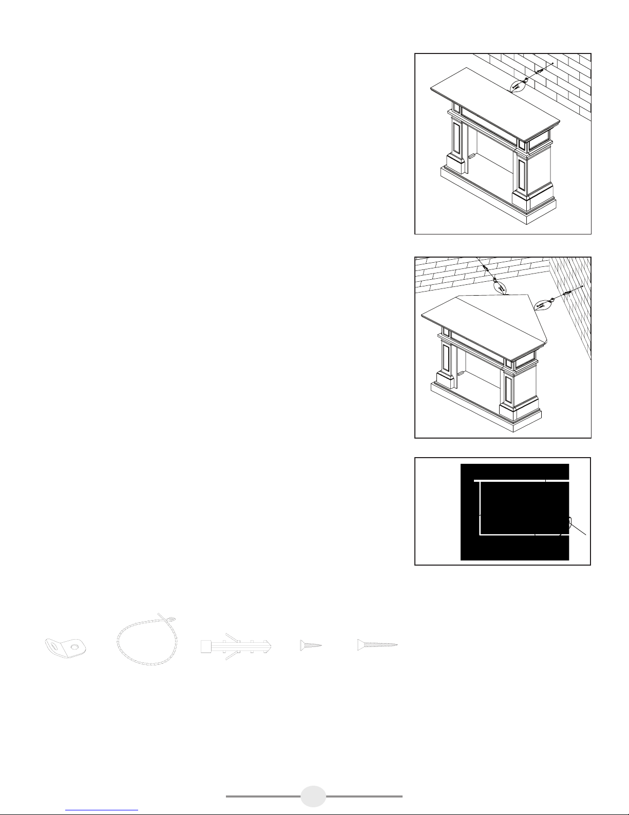
Anti-tipping device (instructions included with hardware)
1. Attach one of the mounting brackets securely to the back edge of
the furniture. Use the shorter screw.
2. Determine where furniture is to be placed and mark location
on the wall for the mounting bracket screw hole approximately 2”
(51mm) below the bracket mounted to the edge of the furniture.
3. Drill a 3/16” (5 mm) hole in the wall. Press the plastic anchor into
the hole and gently tap until the flange on the anchor is against the
wall surface.
4. Position the bracket over the anchor and use the longer screw to
securely attach the bracket to wall.
5. Place the furniture so the bracket on the back edge is in line with
the bracket on the wall.
6. Place an end of the nylon restraint strap down through each
bracket. Bring both ends together and slide the beaded end of
the strap through the keyhole-shaped slot in the other end until
snug. Pull down on the beaded end until it snap locks into the
keyhole slot.
7. To double lock, return the beaded end back through the keyhole
as shown.
8. Check to make sure the strap is securely laced and locked to
the brackets.
Fig. 1
Fig. 2
For a corner application, use 2 furniture tipping restraints as shown
in FIG. 2
Young children may be injured by tipping furniture. The use of a
tipping restraint is highly recommended. This hardware, when
properly installed, could provide protection against the unexpected
tipping of furniture due to improper use.
WARNING: THIS PRODUCT IS ONLY A DETERRENT. IT IS
NOT A SUBSTITUTE FOR PROPER ADULT SUPERVISION.
One anti-tip device includes the following:
2PCS 1PCS 1PCS 1PCS 1PCS
Nylon restraint strap
Plastic
anchor
Bracket
Two anti-tip devices have been included for corner applications.
5

WARRANTY
Greenway Home Products is pleased to offer in-home warranty repairs. Please refer to your Firebox Use and Care Guide for warranty
information on your Firebox.
DO NOT RETURN THIS PRODUCT TO THE STORE:
Please contact Customer Service at: 1-866-253-0447
Monday to Thursday from 8:30AM to 5:00PM (EST), Friday from 8:30AM to 4:00PM (EST)
Web: www.greenwayhp.com
Email: support@greenwayhp.com
Canada:
USA: 1270 Flagship Dr., Perrysburg, Ohio, USA, 43551
Limited Warranty Definitions:
Greenway Home Products:
(Greenway) Manufacturer.
Mantel: Mantel manufactured by Greenway Home Products.
Purchaser: Purchaser of the Mantel
Distributor: Facility authorized to sell Greenway Home Products.
Warranty Card Greenway Home Products Limited Warranty Registration Card identifying the Purchaser and product model.
Greenway Limited Warranty:
Greenway warrants to the Purchaser that the Mantel is free from defects in material and workmanship, under normal use and service, for
1 year (1 year limited parts) from the date of purchase.
All warranty repairs must be preauthorized by Greenway Home Products. Greenway will, at its’ option, replace or repair free of charge
any defective part, which the Purchaser shall notify their Distributor or Greenway Home Products within the warranty period. The obligation
of Greenway Home Products under this warranty, is expressly limited to such replacement or repairs.
The provisions of this limited warranty shall not apply to the following:
1. Accidents.
2. Unauthorized repairs or alterations.
3. Normal maintenance.
4. Changes made to other units manufactured after this mantel was manufactured.
5. Incidental damages caused by failure of the mantel such as inconvenience or loss of use.
6. Improper installation.
400 Southgate Dr., Guelph, Ontario, Canada, N1G 4P5
The provisions of this limited warranty shall not apply to deterioration due to wear and exposure beyond the following limitations:
1. For 180 days from the date of purchase for exterior finished surfaces.
Due to the properties of natural wood, Greenway Home Products makes no warranty against mineraling of wood components.
Greenway Limited Warranty is void unless the following conditions are adhered to:
1. Warranty registration must be completed and returned to a Greenway Home Products.
2. All warranty repairs must be preauthorized by a Greenway repair facility.
3. Greenway reserves the right to inspect defective parts that have been replaced under warranty. Dealer is expected to hold
defective parts for 60 days.
4. Only parts and accessories and other material, available through Greenway Home Products are to be used in the performance
of warranty service.
5. Purchasers are responsible for presenting/notifying their Distributor as soon a problem exists. The warranty repairs should be
completed in a reasonable amount of time from the date of authorization. Not to exceed 30 days past notification.
This limited warranty is expressly in lieu of any other expressed or implied warranty, including any implied warranty or merchantability
or fitness for a particular purpose and of any obligations or liabilities on Greenway Home Products which neither assumes nor
authorizes any other person to assume for it any other liability in connection with the Mantel
manufactured by it.
The warranty is null and void if used in commercial or industrial applications.
6
 Loading...