

Muskoka Madigan MTVS2353SMG-1, Madigan MTVS2353SOK User Manual

MEDIA CONSOLE
Save these instructions | Conserver ces instructions | Guarde estas instrucciones
CONSOLE MÉDIA
CONSOLA DE MEDIOS
MADIGAN
MTVS2353SMG-1 | MTVS2353SOK
Français p. 12
Español p. 22
REV07-02-13
ASSEMBLY TIPS
Before you begin, locate the instructions and hardware. Take out all the parts and compare them to the
diagrams below. Be sure you have all the parts and can identify them. Two people are required to assemble
this product. Assembly time will take approximately 30-90 minutes.
CARE AND MAINTENANCE
1. Dust your fireplace mantel regularly with a soft non-lint producing cloth or household dusting product.
2. You can clean your fireplace insert with a gentle non-abrasive household cleaner. Make sure to dry
your fireplace immediately with a soft cloth or towel.
P
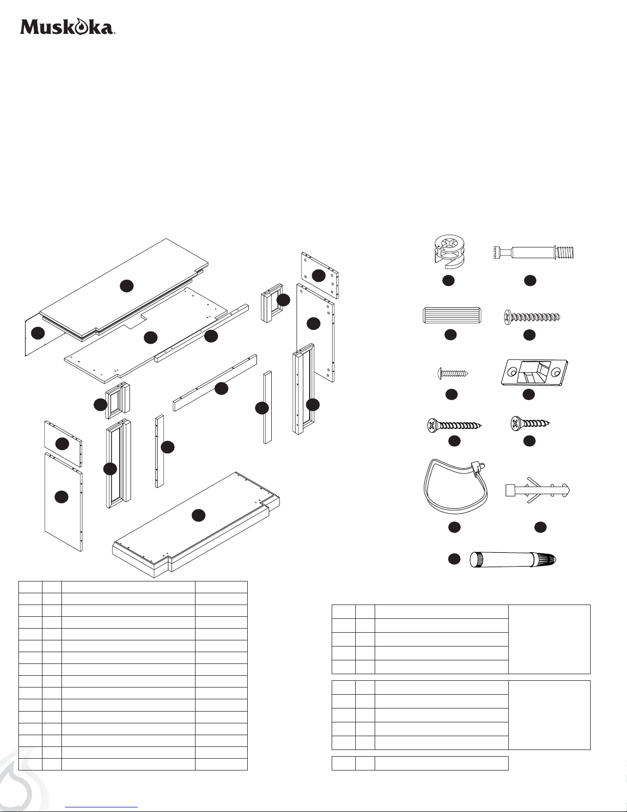
PARTS
E
A
a b
I
G
B
J
M
H
D
N
O
L
c
e
g h
d
f
K
F
C
i
k
J
A 1 TOP ZZ.2353.A
B 1 SHELF ZZ.2353.B
C 1 BASE ZZ.2353.C
D 1 LEFT TOP SIDE PANEL ZZ.2353.D
E 1 RIGHT TOP SIDE PANEL ZZ.2353.E
F 1 LEFT SIDE PANEL ZZ.2353.F
G 1 RIGHT SIDE PANEL ZZ.2353.G
H 1 LEFT TOP FRONT PANEL ZZ.2353.H
I 1 RIGHT TOP FRONT PANEL ZZ.2353.I
J 1 TOP TRIM ZZ.2353.J
K 1 LEFT FRONT PANEL ZZ.2353.K
L 1 RIGHT FRONT PANEL ZZ.2353.L
M 1 TOP OPENING TRIM ZZ.2353.M
N 1 LEFT OPENING TRIM ZZ.2353.N
O 1 RIGHT OPENING TRIM ZZ.2353.O
P 1 BACK PANEL ZZ.2353.P
2
HARDWARE
a 37 CAM LOCK
b 37 CAM LOCK DOWEL
c 42 WOOD DOWEL
d 3 LARGE SCREW
e 16 SMALL SCREW
f 2 MOUNTING BRACKET
g 2 LARGE SCREW
h 2 SMALL SCREW
i 1 NYLON STRAP
J 2 ANCHOR
k 1 TOUCH UP PAINT
SPARES
INCLUDED
ANTI-TIP DEVICE
2 SETS
INCLUDED
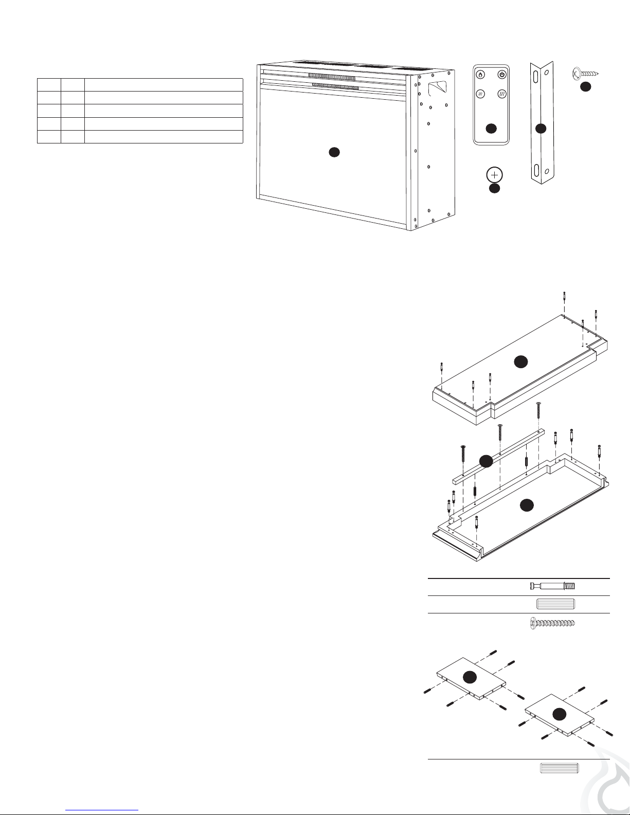
FIREBOX PACKAGE CONTENTS
AAA AAA
Q 1 FIREBOX
R 1 REMOTE
S 2 CR2032 BATTERY
T 3 METAL TRIM
U 7 FIREBOX TRIM SCREW
R
Q
S
T
U
ASSEMBLY
Before assembly, use scissors to unwrap the parts from the packaging. DO NOT use a box cutter or
exacto-knife as you may cut into the mantel pieces inside the box and damage the finish. Check for the
hardware bag which is RED and located inside the packaging, taped to the top box. DO NOT discard
any pieces.
1. Locate the base (C). Insert and tighten 6 cam lock dowels (b) into
the base (C). Make sure the threaded side is down so you can inset
C
and tighten each cam lock dowel (b) into each hole in the base (C).
Locate the top (A) and place it finished side down on a soft clean
surface. Insert and tighten 6 cam lock dowels (b) into the top (A).
Make sure the threaded side is down so you can insert and tighten
each cam lock dowel (b) into each hole in the top (A). Insert 2 wood
dowels (c) into the holes on the underside of the front of the top A.
Line up the holes in the top trim piece J with the wood dowels in the
top A. Push piece J down until flush with the top A. Secure piece J
to top A by inserting 3 long screws (d) into piece J and tightening
until secure.
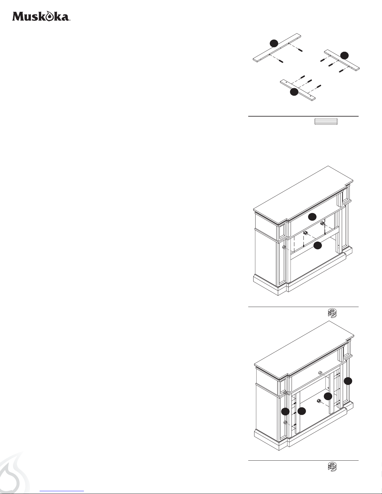
2. Locate the left and right top side panels (D & E). Insert 6 wood
dowels (c) into the edges of each panel as shown.
J
A
Hardware Used
b Cam Lock Dowel x 12
c Wood Dowel x 2
d Large Screw x 3
D
E
Hardware Used
c Wood Dowel x 12
3

3. Insert 6 cam lock dowels (b) into the holes on the top of shelf B.
Make sure the threaded side is down so you can insert and tighten
each cam lock dowel into the panels.
Flip shelf B over and insert 9 cam lock dowels (b) into the holes on
the bottom of shelf B. Make sure the threaded side is down so you
can insert and tighten each cam lock dowel into the panels.
4. Locate the top front panel H. Insert 1 cam lock dowel (c) into the
center hole on the back of panel H. Make sure the threaded side is
down so you can insert and tighten each cam lock dowel into the
panels. Insert 2 wood dowels on either end of the top front panel H.
Repeat process for top front panel I.
B
B
Hardware Used
b Cam Lock Dowel x 15
H
Hardware Used
b Cam Lock Dowel x 2
I
5. Locate the left and right front panels (K & L). Insert 1 wood dowel
(d) into each the end of each panel K & L. Insert 2 cam lock dowels
into the back of each panel K & L. Insert 2 cam lock dowels into
the outer edge of each panel K & L. Make sure the threaded side is
down so you can insert and tighten each cam lock dowel into each
panel.
c Wood Dowel x 4
K
L
Hardware Used
b Cam Lock Dowel x 8
c Wood Dowel x 4
4

6. Locate side panels F & G. Insert 6 wood dowels into the edge of
each panel.
7. Line up and insert cam lock dowels and wood dowels on panels
F and K and push together until flush. Insert 2 cam locks into the
holes on panel F. Make sure the arrows on the cam locks are facing
toward panel K. Turn the cam locks to tighten. Do not strip the cam
locks by over tightening.
F
G
Hardware Used
c Wood Dowel x 12
F
G
K
Repeat process for panels G and L.
8. Line up the wood dowels in panel D with the holes in panel H
and the cam lock dowel in panel H with the holes in panel D.
Push together until flush. Insert a cam lock into the center hole at
the bottom of panel D. Make sure the arrows on the cam lock are
facing toward panel H. Turn the cam lock to tighten. Do not strip
the cam lock by over tightening.
Repeat the process for panels E and I.
L
Hardware Used
a Cam Lock x 4
D
E
H
I
Hardware Used
a Cam Lock x 2
5
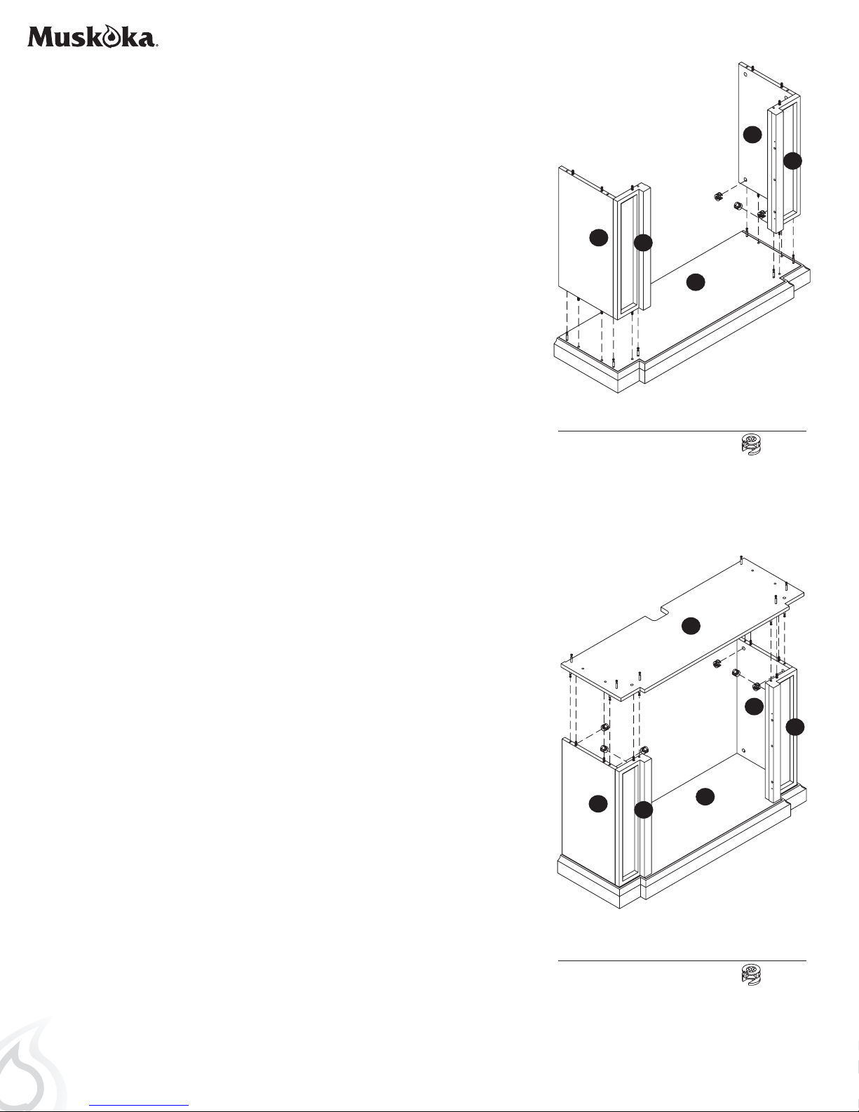
9. Line up the wood dowels in the bottom of panels F & K with the
holes in the base C. Also line up the cam lock dowels in the base
C with the holes in the bottom of panels F & K. Push the assembly
of panels F & K down until flush with the base C. Once flush, insert
cam locks at the bottom of panels F & K making sure the arrows on
the cam locks are facing down toward the base C. Turn the cam
locks to tighten. Do not strip the cam locks by over tightening.
G
L
F
K
Repeat the process for panels G & L.
10. Line up the wood dowels in the top edge of panels F, K, G, & L
with the holes on the bottom of shelf B and the cam lock dowels
in the bottom of shelf B with the holes on the top edge of panels F,
K, G, & L. Push the shelf B down on the mantle assembly until flush.
Insert cam locks into the holes on panels F, K, G, & L. Make sure
the arrows on the cam locks are facing up toward shelf B. Turn the
cam locks to tighten. Do not strip the cam locks by over tightening.
C
Hardware Used
a Cam Lock x 6
B
G
L
6
F
Hardware Used
a Cam Lock x 6
K
C
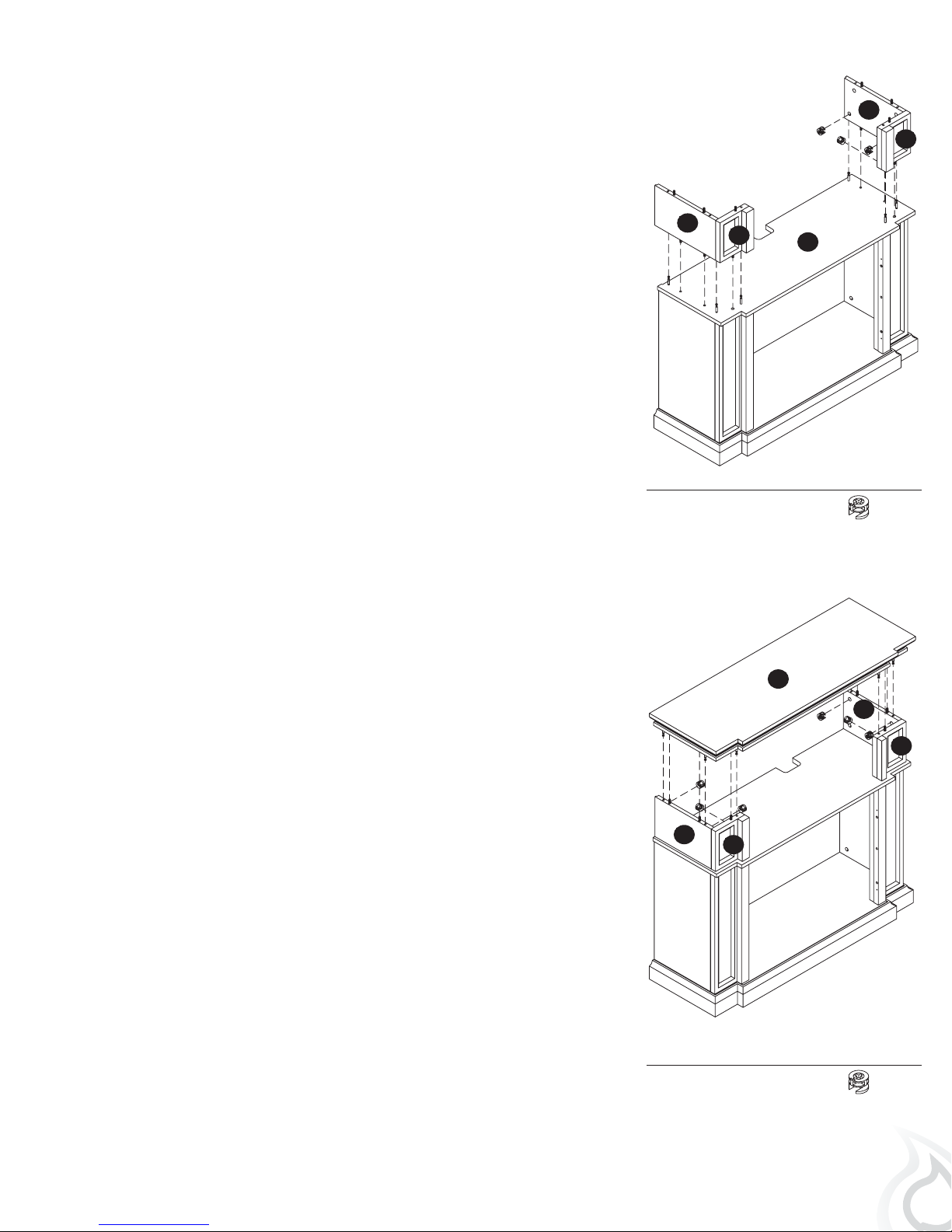
11. Line up the wood dowels in panels D & H with the holes on the top
of shelf B and the cam lock dowels on shelf B with the holes in the
bottom edge of panels D & H. Push panels D & H down onto shelf
B until flush. Insert 3 cam locks into the bottom holes of panels D &
H. Make sure the arrows on the cam locks are facing down toward
shelf B. Turn the cam locks to tighten. Do not strip the cam locks by
over tightening.
Repeat process for panels E & I.
E
D
Hardware Used
a Cam Lock x 6
H
B
I
12. Note: Top is heavy. It is recommended that 2 people be used at this
point in the assembly.
Line up the wood dowels in the top of the mantel assembly with
the holes in the underside of top A. Also make sure the cam lock
dowels on the underside of top A are lined up with the holes in
the in the top of the mantel assembly. Push top A down until flush.
Insert 6 cam locks into the holes on panels D, H, E, and I. Make
sure the arrows on the cam locks are facing up toward the top A.
Turn the cam locks to tighten. Do not strip the cam locks by over
tightening.
D
Hardware Used
H
A
E
I
a Cam Lock x 6
7
13. Locate panels M, N & O. Insert 8 wood dowels into the edge of
each panel.
14. Place panel M, making sure the finished side is facing out, into the
firebox opening and up against panel J on shelf B. Make sure the
wood dowels in panel M line up with the holes in panel J and the
cam lock dowels in panel J line up with the holes in panel M. Once
panel M is flush with panel J insert 3 cam locks on the back side
of panel M making sure the arrows on the cam locks are facing up
toward the shelf B. Turn the cam locks to tighten. Do not strip the
cam locks by over tightening.
M
N
O
Hardware Used
c Wood Dowel x 8
B
M
15. Place panel N, making sure the finished side is facing out, into
the firebox opening and up against panel K. Make sure the wood
dowels in panel N line up with the holes in panel K and the cam
locks dowels in panel K line up with the holes in panel N. Once
panel N is flush with panel K insert 2 cam locks on the back side
of panel N making sure the arrows on the cam locks are facing
toward panel K. Turn the cam locks to tighten. Do not strip the cam
locks by over tightening.
Repeat process for panels O & L.
8
Hardware Used
a Cam Lock x 3
O
N
K
Hardware Used
a Cam Lock x 4
L
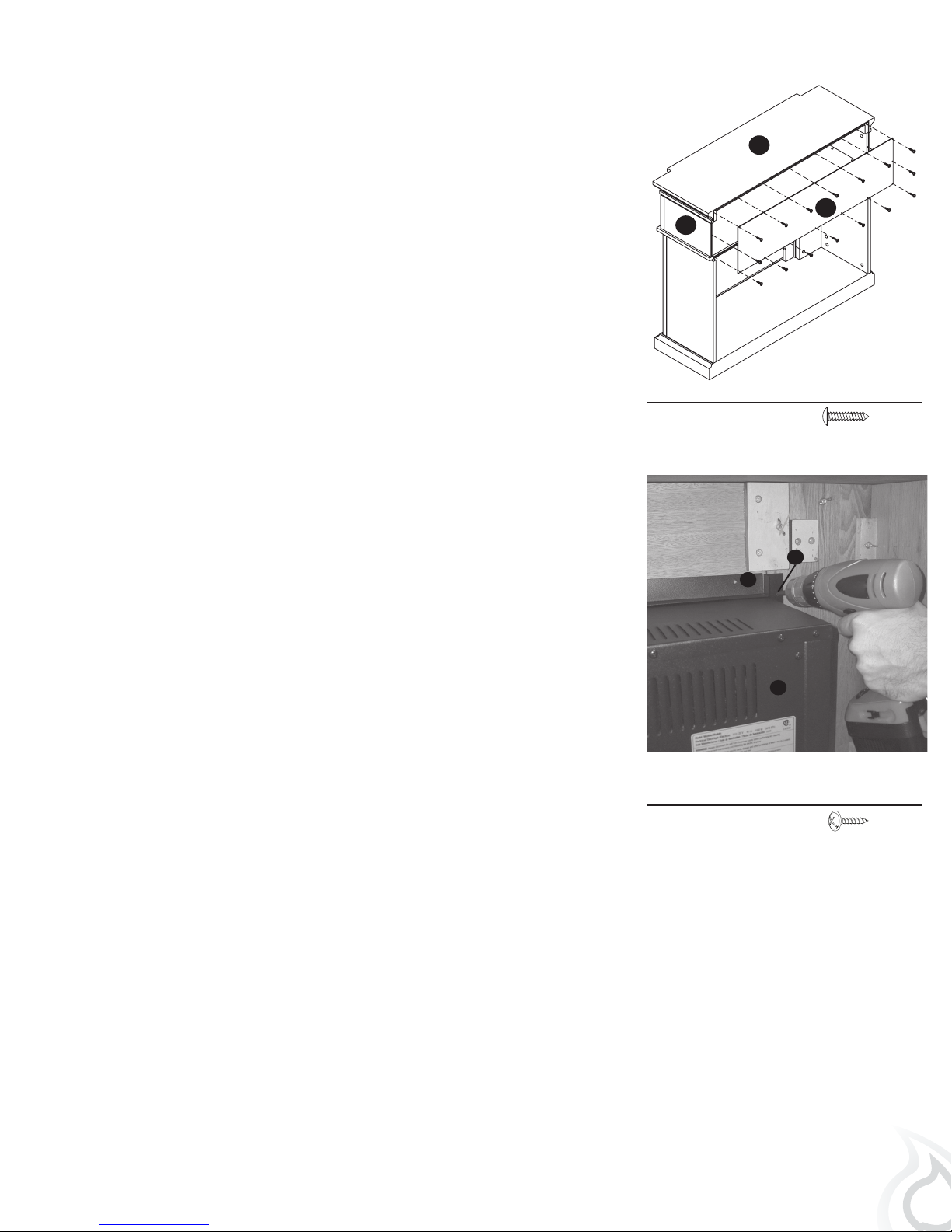
16. Locate back panel P. Making sure the finished side is facing in
toward the mantel, line up the holes in panel P with the holes on
the back of the mantel. Secure panel P to the mantel using 16 small
screws (e). Tighten until secure.
17. Installing your electric firebox
Refer to the manual included in your electric firebox carton. It will provide
you with the step by step instructions to prepare the electric firebox,
maintenance instructions and the firebox functions prior to installation
in the media console.
A
P
E
Hardware Used
e Small Screw x 16
U
T
The firebox comes with 3 metal brackets and 11 black screws (10
required plus 1 spare). These metal brackets must be attached to all 3
sides of the firebox and 2 sides of the mantel to ensure that your firebox
does not move around as you use it.
Insert your firebox from the rear of the mantel and position between the
two opening trims.
The top trim does not attach to the mantel, just the firebox. If you have any
questions about the firebox please reference the installation instructions
that come with the firebox.
Q
Hardware Used
U Firebox Trim Screw x 10
9
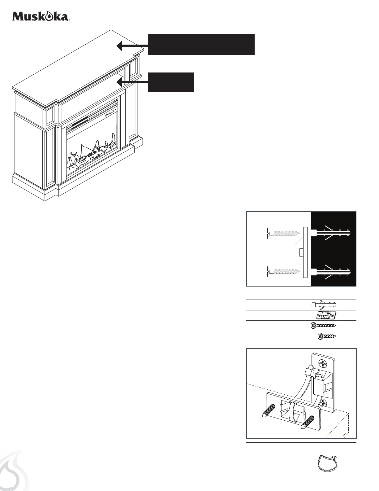
FIT UP TO 47" PLASMA/LCD/LED TELEVISIONS
MAXIMUM LOAD 55 lb. (25 kg)
MAXIMUM LOAD
30 lb. (13.6kg)
CAUTION: This unit is intended for use only with the products
and maximum weights indicated. Use with other products or
products heavier than the maximum weights indicated may
result in instability causing possible injury.
Note: Flat Panel TVs with base support should be placed
squarely in the center of the stand with no overhang on any side.
ANTI-TIPPING DEVICE (instructions included with hardware)
1. Attach one of the mounting brackets (f) securely to the back edge
of the furniture. Use the small screws (h).
2. Determine where furniture is to be placed and mark location on
the wall for the other mounting bracket (f) screw holes. You may
need to use 2 anchors (j) if you are attaching to drywall or plaster.
3. Position the bracket over the holes and use the large screws (g) to
securely attach the bracket to wall.
4. Place the furniture so the mounting bracket (f) on the back edge is
in line with the mounting bracket (f) on the wall.
5. Place an end of the nylon restraint strap (i) down through each
bracket (f). Bring both ends together and slide the end of the
nylon strap (i) through the slot in the other end until snug. Pull
down on the end until it snap locks into the slot.
6. Check to make sure the strap (i) is securely laced and locked to
the mounting brackets (f).
Young children may be injured by tipping furniture. The use of a
tipping restraint is highly recommended. This hardware, when
properly installed, could provide protection against the unexpected
tipping of furniture due to improper use.
WALL
Hardware Used
j
Anchor x 2
f
Mounting Bracket x 2
g
Large Screw x 2
h Small Screw x 2
WARNING: This product is only a deterrent. It is not a substitute for
proper adult supervision.
10
Hardware Used
i Nylon Strap x 1
 Loading...