

Muskoka 25-1000-001, GLF-2505, GLF-2507 Use And Care Manual
ELECTRIC FIREBOX FOYER ÉLECTRIQUE HOGAR ELÉCTRICO
USE AND CARE GUIDE | GUIDE D’UTILISATION ET D’ENTRETIEN | GUÍA DE USO Y CUIDADO
25-1000-001 / GLF-2505 / GLF-2507
IMPORTANT:
SAVE THESE
INSTRUCTIONS.
PLEASE READ THIS MANUAL BEFORE
INSTALLING AND USING APPLIANCE
IF THE INFORMATION IN THIS MANUAL IS NOT FOLLOWED
EXACTLY, AN ELECTRICAL SHOCK OR FIRE MAY RESULT
CAUSING PROPERTY DAMAGE, PERSONAL INJURY OR LOSS OF LIFE.
Retain this manual for future use.
WARNING!
IMPORTANT :
CONSERVER CES
INSTRUCTIONS.
VEUILLEZ LIRE CE MANUEL AVANT L’INSTALLATION
ET L’UTILISATION DE VOTRE FOYER
SI LES RENSEIGNEMENTS DE CE MANUEL NE SONT PAS EXACTEMENT
SUIVIS, UN CHOC ÉLECTRIQUE OU UN INCENDIE PEUT SURVENIR, ET
CAUSER DES DOMMAGES, DES BLESSURES OU LA PERTE DE VIE
Conserver ce manuel pour une utilisation ultérieure.
AVERTISSEMENT!
IMPORTANTE:
GUARDE ESTAS
INSTRUCCIONES.
POR FAVOR LEA LAS INSTRUCCIONES DE
INSTALACIÓN Y DE OPERACIÓN ANTES DE
USAR ESTE CAJA DE FUEGO
SI NO SIGUE EXACTAMENTE LA INFORMACIÓN EN ESTE MANUAL, PODRÍA
RESULTAR EN CHOQUES ELÉCTRICOS O INCENDIO QUE PUEDEN CAUSAR
DAÑOS A LA PROPIEDAD, LESIONES PERSONALES O LA PÉRDIDA DE LA VIDA.
Guarde este manual para futuras referencias.
¡ADVERTENCIA!
Français p. 18 | Español p. 3420-10-245

Table of Contents
Table of Contents ...........................2
Safety Information ...........................2
User Instructions ............................ 3
Grounding Instructions ......................3
Locating Your Fireplace ..................... 3
Firebox Specications ....................... 3
Electrical Connection ....................... 3
Remote Control ............................ 4
Warranty ...................................5
Pre-Installation ..............................6
Planning Installation ........................ 6
Tools Required ............................6
Hardware Included ........................6
Package Contents .........................6
Installation .................................7
Mantel Installation .......................... 7
Operation. . . . . . . . . . . . . . . . . . . . . . . . . . . . . . . . . . 8
Maintenance .............................. 15
Glass information. . . . . . . . . . . . . . . . . . . . . . . . . . 15
Maintenance of Motors ....................15
Battery Replacement ...................... 15
Care and Cleaning. . . . . . . . . . . . . . . . . . . . . . . . . 15
Circuit Diagram ............................ 16
Troubleshooting ............................ 16
Service Parts ...............................17
Safety Information
1. Read all instructions before using this heater.
2. This heater is hot when in use. To avoid burns, do not let bare skin touch hot surfaces. If provided, use
handles when moving this heater. Keep combustible materials, such as furniture, pillows, bedding, papers,
clothes, and curtains at least 3 feet (0.9 meters) from the front of the heater and keep them away from the
sides and rear.
3. Extreme caution is necessary when any heater is used by or near children or invalids and whenever the
heater is left operating and unattended.
4. Always unplug heater when not in use.
5. Do not operate any heater with a damaged cord or plug or after the heater malfunctions, has been
dropped or damaged in any manner. Return heater to authorized service facility for examination,
electrical or mechanical adjustment, or repair.
6. Do not use outdoors.
7. This heater is not intended for use in bathrooms, laundry areas and similar indoor locations. Never locate
heater where it may fall into a bathtub or other water container.
8. Do not run power cord under carpeting. Do not cover power cord with throw rugs, runners, or the like.
Arrange power cord away from trafc area and where it will not be tripped over.
9. To disconnect heater, turn controls to off, then remove plug from outlet.
10. Connect to properly grounded outlets only.
11. Do not insert or allow foreign objects to enter any ventilation or exhaust openings as this may cause an
electric shock or re, or damage the heater.
12. To prevent a possible re, do not block rebox air intakes or exhaust in any manner. Do not operate rebox
on soft surfaces, like a bed, where openings may become blocked.
13. A heater has hot and arching or sparking parts inside. Do not use in areas where gasoline, paint, or
ammable liquids are used or stored.
14. Use this heater only as described in this manual. Any other use not recommended by the manufacturer
may cause re, electrical shock, or injury to persons.
15. Avoid the use of an extension cord because of the risk of overheating the cord and the risk of re.
Extension cords are for temporary use only. If an extension cord must be used, it must be UL/CSA certied,
rated at 15A (1875W), 125V maximum with 14 AWG minimum and constructed of two current carrying
conductors with ground. A heavy duty extension cord with the shortest length possible for the connection
is recommended and must not be longer than 50 ft. (15.2 m). Do not coil or cover the extension cord.
16. This electric replace is not designed for “zero” clearance wall and/or cabinet/millwork installations.
Accessibility for servicing and maintenance must be possible without disturbing building structures and/or
cabinet/millwork nishes.
17. SAVE THESE INSTRUCTIONS
2

Safety Information (continued)
USER INSTRUCTIONS
1. Any repairs to this appliance should be carried out by qualied/authorized service personnel only.
2. Under no circumstances should this appliance be modied. Parts having to be removed for servicing must
be replaced with original “OEM” (original equipment manufacturers) parts only.
3. This rebox is to be cleaned with a damp cloth (water) only.
IMPORTANT: Always unplug the power cord before cleaning the unit. Do not use any abrasive cleaners on
the unit.
4. Unplug this rebox when not in use.
5. Remove cardboard support from log set before activating rebox.
To remove glass panel see “Installing the ember beds”.
GROUNDING INSTRUCTIONS
This heater is for use on 120 volts. The cord has a plug as shown in gure
1A in the diagram. An adapter as shown in gure 1C is available for
connecting three-blade grounding-type plugs to two-slot receptacles. The
green grounding lug extending from the adapter must be connected to a
permanent ground such as a properly grounded outlet box. The adapter
should not be used if a three-slot grounded receptacle is available.
(Note: Grounding adapter use prohibited in Canada)
Grounding Pin
Cover of Grounded Outlet Box
C
Adapter
Grounding Lug
Metal Screw
Cover of Grounded Outlet Box
LOCATING YOUR FIREPLACE
When choosing a location for your new replace, ensure the general instructions are followed. Also, for best
effect install the replace out of direct sunlight. It is safe to set the replace insert close to non-combustibles.
A
B
25-1000-001 SPECIFICATIONS
DO NOT STORE OR USE GASOLINE
OR OTHER FLAMMABLE VAPORS
OR LIQUIDS IN THE VICINITY OF
THIS OR ANY OTHER APPLIANCE.
Fireplace Insert dimensions
(w x d x h)
Voltage 120 V
Frequency 60 Hz
Watts • Amps. 1440W • 12A
Heater Rating 4600 BTU's
26.4” x 9.5”x 19”
67cm x 24,2cm x 48,4cm
ELECTRICAL CONNECTION
A 15 Amp, 120 Volt, 60 Hz circuit with a properly grounded outlet is required to operate this appliance. Preferably,
the replace insert will be on a dedicated circuit as other appliances on the same circuit may cause the circuit
breaker to trip or the fuse to blow when the heater is in operation. The unit comes standard with a 6 ft (1.8 m) long
3 wire cord, exiting out the back of the replace insert. Plan the installation to avoid the use of an extension cord.
If an extension cord must be used, it must be a minimum 14 ga, 3 wire with grounding type plug and connector
and rated not less than 1875 watts. The extension cord shall not be more than 50 ft (15.2 m) in length.
WARNING: Electrical outlet wiring must comply with local building codes and other applicable
regulations to reduce the risk of re, electrical shock and injury to persons.
WARNING: Do not use this replace if any part of it has been under water. Immediately call a qualied service
technician to inspect the replace and replace any part of the electrical system which has been under water.
3
Safety Information (continued)
REMOTE CONTROL
This device complies with Industry Canada license-exempt RSS standard(s). Operation is subject to the following
two conditions: (1) this device may not cause interference, and (2) this device must accept any interference,
including interference that may cause undesired operation of the device.
This Class (B) device complies with Part 15 of the FCC Rules and Canadian ICES-003. Operation is subject to the
following two conditions:
(1) This device may not cause harmful interference, and (2) this device must accept any interference received,
including interference that may cause undesired operation. There is no guarantee that interference will not occur
in a particular installation. If this equipment does cause harmful interference to radio or television reception,
which can be determined by turning the equipment o and on, the user is encouraged to try to correct the
interference by one or more of the following measures:
• Reorient or relocate the receiving antenna.
• Increase the separation between the equipment and receiver.
• Connect the equipment into an outlet on a circuit dierent from that to which the receiver is connected.
• Consult the dealer or an experienced radio/TV technician for help.
This remote control requires 1 Lithium Coin Cell Battery (size CR2025), which is included.
CAUTION: Changes or modications to this unit not expressly approved by the party responsible for compliance
could void the user’s authority to operate the equipment.
DO NOT mix old and new batteries.
DO NOT use rechargeable silver oxide cell batteries with remote control unit.
DO NOT mix alkaline, standard (Carbon-Zinc), or rechargeable (Nickel-Cadmium) batteries.
DO NOT dispose of batteries in re. Improper disposal may cause batteries to leak or explode.
WARNING: Never attempt to disassemble or alter the product in any way not instructed by this manual.
BLUETOOTH® CERTIFICATE
Declaration ID D030802
Qualied Design ID 71830
4
1 Year Warranty
WHAT IS COVERED
The manufacturer warrants that your new electric replace is free from manufacturing and material defects for a
period of one year from date of purchase, subject to the following conditions and limitations.
This electric replace must be installed and operated at all times in accordance with the instructions furnished
with the product. Any alteration, willful abuse, accident, or misuse of the product shall nullify this warranty. This
warranty is non-transferrable, and is made to the original owner, provided that the purchase was made through
an authorized supplier of the manufacturer.This warranty is limited to the repair or replacement of part(s) found to
be defective in material or workmanship, provided that such part(s) have been subjected to normal conditions
of use and service, after said defect is conrmed by the manufacturer’s inspection. The manufacturer may, at
its discretion, fully discharge all obligations with respect to this warranty by refunding the wholesale price of the
defective part(s).
WHAT IS NOT COVERED
Any installation, labor, construction, transportation, or other related costs/expenses arising from defective part(s),
repair, replacement, or otherwise of same, will not be covered by this warranty, nor shall the manufacturer
assume responsibility for same. Further, the manufacturer will not be responsible for any incidental, indirect, or
consequential damages, except as provided by law.
All other warranties - expressed or implied - with respect to the product, its components and accessories, or any
obligations/liabilities on the part of the manufacturer are hereby expressly excluded. The manufacturer neither
assumes, nor authorizes any third party to assume, on its behalf, any other liabilities with respect to the sale of this
product. The warranties as outlined within this document do not apply to nonmanufacturer accessories used in
conjunction with the installation of this product.
This warranty does not cover the light bulb(s) included with the replace.
This warranty is void if: the replace has been operated in atmospheres contaminated by chlorine, uorine, or
other damaging chemicals; the replace is subjected to prolonged periods of dampness or condensation; the
replace is altered, willfully abused, damaged by accident, or misused in any way.
Make sure you have your warranty, your sales receipt, and the model/serial number of your product.
DO NOT ATTEMPT TO DO ANY SERVICE WORK YOURSELF. PLEASE CONTACT CUSTOMER SERVICE AT:
1-866-253-0447 Monday to Thursday from 8:30AM to 5:00PM (EST),
Friday from 8:30AM to 4:00PM (EST)
Web: www.greenwayhp.com
Email: support@greenwayhp.com
Canada: 400 Southgate Dr., Guelph, Ontario, Canada, N1G 4P5
USA: 6440 W. Howard Street, Niles, Illinois U.S.A. 60714
5
Pre-Installation
PLANNING INSTALLATION
To avoid scratching the nish, assemble the product on a soft, non-abrasive surface, such as carpet or cardboard.
Assembly of this product may require more than one person.
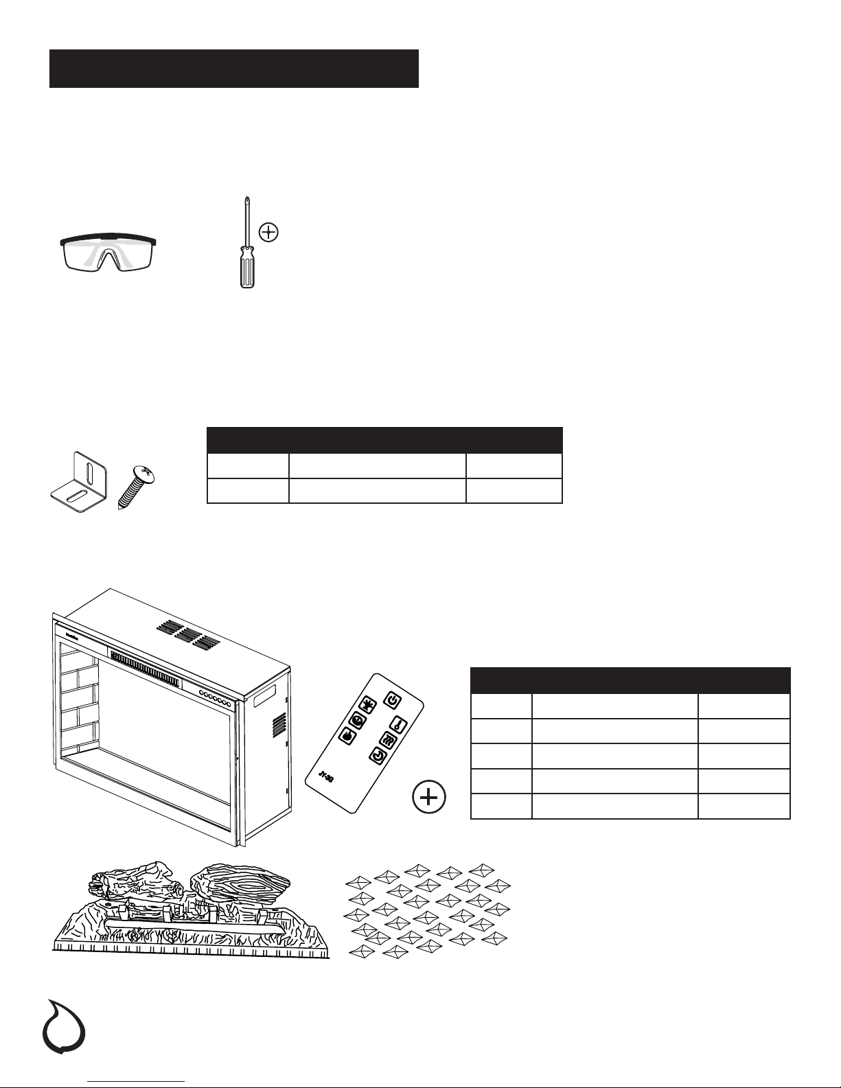
TOOLS REQUIRED
Safety Goggles Phillips screwdriver
HARWARE INCLUDED
Note: Hardware not shown to actual size.
AA BB
PART DESCRIPTION QUANTITY
AA Mounting Brackets 2
BB Screws 4
PACKAGE CONTENTS
PART DESCRIPTION QUANTITY
A Fireplace Insert 1
B Log Set 1
C Acrylic Crystal 1
D Remote control 1
E Battery (pre-installed) 1
A
B
6
D
E
C
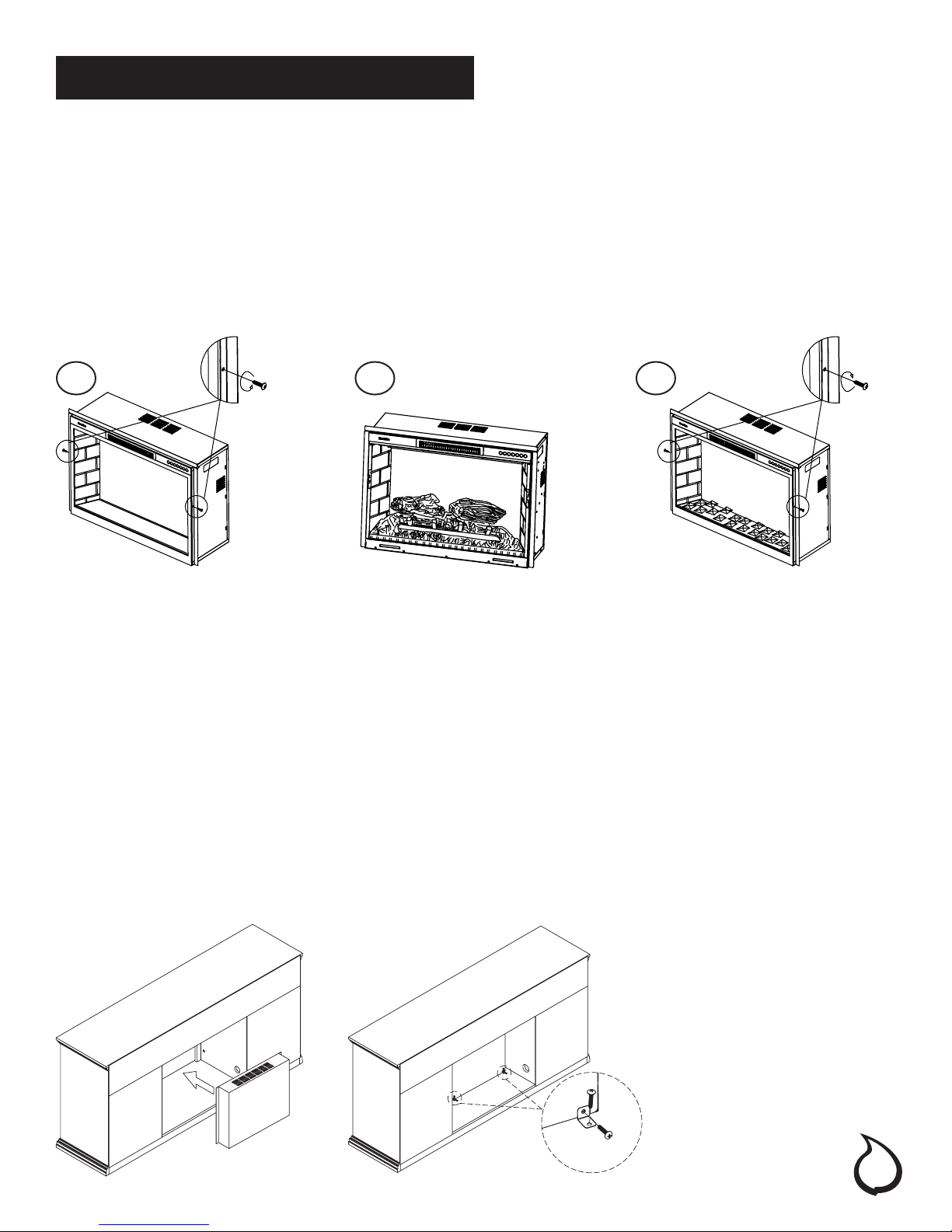
Installation
INSTALLING THE EMBER BEDS
You will need one phillips head screwdriver and remove the 3 ember beds from the carton to complete the
following instructions:
1. Remove the 2 screws on the left and right sides of the rebox that hold the glass front in place. Carefully
remove the glass front.
2. Arrange the ember beds (acrylic crystals or log set) along the inset window ledge at the front of the
electric rebox
3. Replace the glass front. Line up the holes on the front with the holes on the rebox and insert and tighten 2
screws to hold the glass front in place.
1. 2. 3.
B or C
MANTEL INSTALLATION
1. Place the assembled mantel near a 15-amp, 120-volt grounded electric outlet.
2. Place the insert directly in front of the mantel opening.
3. Carefully lift the insert through the center opening in the front of the replace. The bottom of the insert has
two foam rubber strips to prevent scratching of the hearth base. Slide the insert back through the opening
until the metal trim makes contact with the front of the mantel.
4. Install the mounting brackets provided with the insert in the pre-drilled holes on the bottom of the insert
(see Figure 2).
5. Carefully position mantel with installed replace against wall.
6. Plug the power cord into the 15-amp, 120-volt outlet.
CAUTION: Make sure that the unit is installed so that the power cord is not compressed against or caught on the
unit or the mantel and that it has an unobstructed path to the grounded outlet.
Figure 2.
AA
BB
7
Operation
The replace control functions can be accessed in two (2) ways:
1. Using the touchpad control panel, located in the upper right-hand corner of the replace.
2. Using the multifunction remote control.
The replace features conveniently separate controls for ame effect and for heater control. This allows you to
operate the unit in two (2) different modes:
1. As a full-featured replace - both ame effect and heater are on.This mode allows you to enjoy the look of
the re along with the heat output of a heater.
2. As a visual effect - only the ame effect is on, the heater is off. We recommend this mode for warm weather
application, when you want the ambiance of a re, without any heat output.
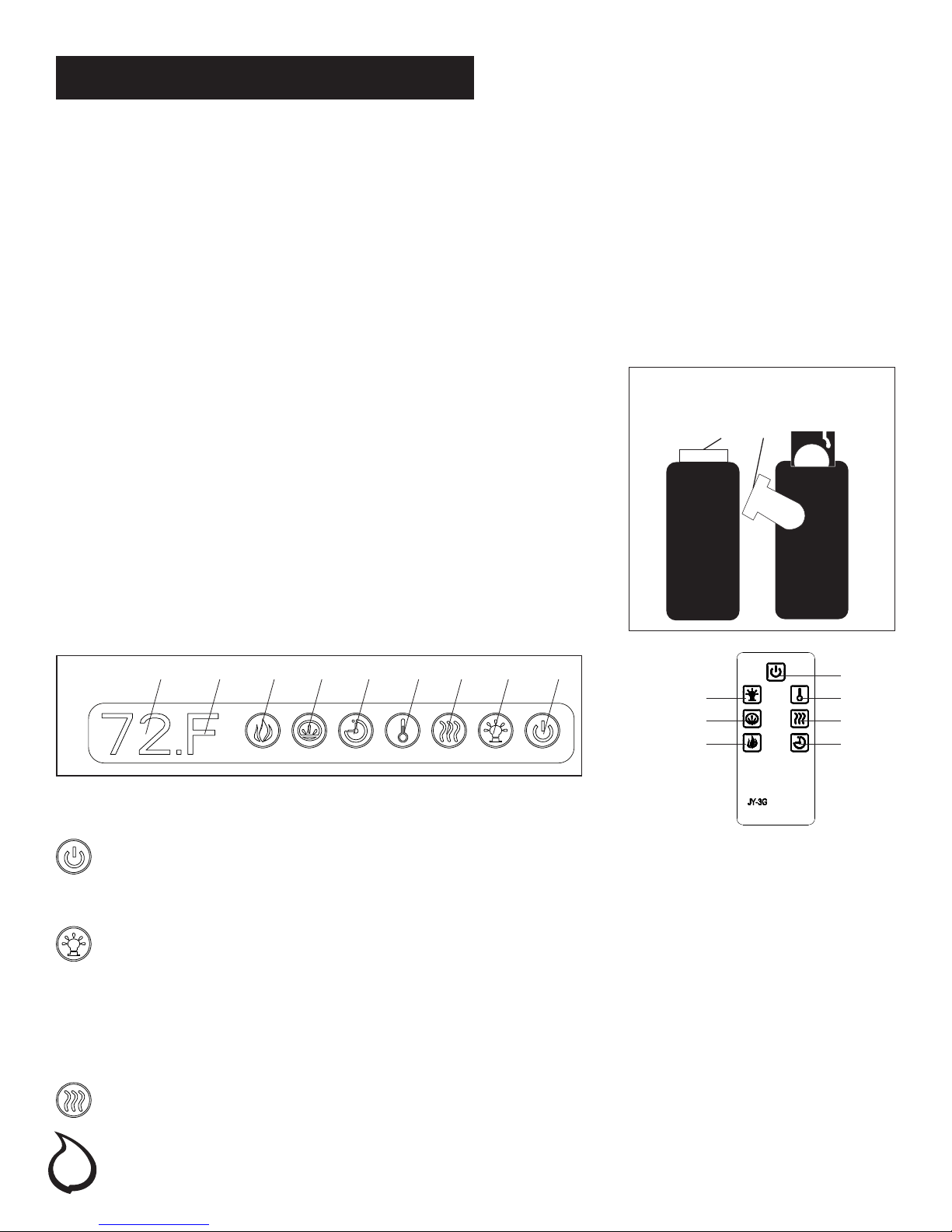
REMOTE CONTROL INFORMATION
The infrared remote control relies on a line of sight and must be pointed at
the ame/screen of the replace to work. The remote control unit has the
controls required to turn ON/OFF both the main power and the heater. If
you prefer, use the touchpad control on the replace unit itself.The layout
of the buttons on touchpads and remote control unit can be seen in
Figures 3 and 4, respectively.
1. Plug your replace into a 15-amp, 120-volt power outlet.
2. Turn the power on. Flame will show on the back screen of the
replace.
3. Remove plastic tab from inside battery compartment to activate
remote control.
4. Point the remote control directly at the replace ame/screen and
use the buttons to operate the replace.
The plastic tab inside the battery
compartment MUST be removed
before the remote control will operate.
(Pull Tab)
Figure 3. Figure 4.
123456789
2
6
7
1. MAIN POWER BUTTON
This button supplies power to all the functions of the replace. The Main Power button must be in the ON
position, either from the remote or on the touch pad for the functions to work.
2. FLAME BRIGHTNESS CONTROL
This button controls the brightness of the ame effect with settings at High(C3), Medium(C2), and
Low(C1). When rst turned on, the ame will come on at the highest setting. The log set will remember
the last ame setting used, unless power to the unit has been interrupted. Each time the ame button is
pressed, the ame brightness increases. The only way to turn off the ame effect completely is to turn off
the main power button.
3. HEATER BUTTON
Heater on / off. There are 2 operation modes:
OFF is to turn off the heater. ON is to turn on the heater.
1
4
3
5
8
Operation (continued)
4. TEMPERATURE ADJUSTMENT BUTTON
This button displays F(Fahrenheit) or C(Celsius) depending on how the temperature mode is set.
When the temperature unit is set as ‘F”, the temperature scope is as follows:
“F” =Fahrenheit temperature 86°F, 84°F, 82°F, 80°F, 78°F, 76°F, 74°F, 72°F, 70°F, 68°F, 66°F, 64°F, 62°F.
“C” =Celsius temperature 30°C, 29°C, 28°C, 27°C, 26°C, 25°C, 24°C, 23°C, 22°C, 21.C, 20°C, 19°C, 18°C, 17°C.
5. TIMER BUTTON
This button controls the timer ON/OFF and 8-time setting from 1H to 8H. When the Timer is rst turned on,
it will come on at the shortest time setting (1H). Each time the Timer button is pressed, the time increases
1 hour, up to the longest setting (8 hours). Once the set time expires, all replace functions will be
automatically turned off.
6. EMBER BED COLOR
Pressing the ember bed control button once lights the ember bed. Continue to press the ember bed
control button to cycle through different colors of the ember bed.
E1 :Orange E2 :Blue E3: Orange mixed with Blue E4: equals to 3 colors,E1,E2,E3 will cycle each 5 seconds.
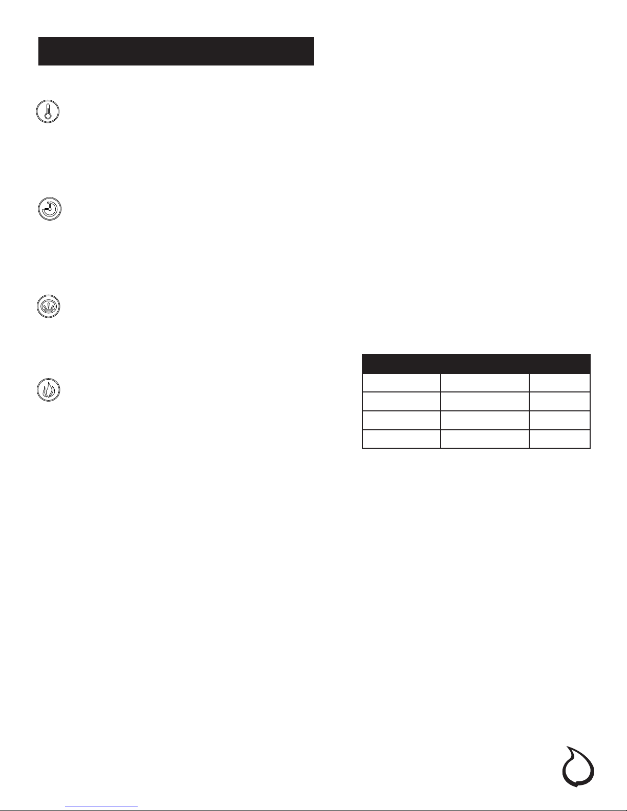
7. FLAME COLOR
Pressing the ame control button once turns ames on.
Continue to press the ame control button to cycle
through different colors of the ame. Reference the table
for more information.
BUTTON PRESS FLAME COLOR DISPLAY
1 Orange A1
2 Blue A2
3 Orange & Blue A3
4 Color Rotation A4
8. FAHRENHEIT/CELSIUS DISPLAY
This button displays F (Fahrenheit) or C (Celsius) depending on how the temperature mode is set. When the
replace is rst turned on, the Fahrenheit (F) temperature will be displayed. To switch from Fahrenheit to Celsius,
or vise-versa, when HEATER is ON, hold HEATER CONTROL button for 10 seconds. The replace will remember
the last temperature mode setting, and in later use, the display will start at that setting, unless power to the unit
has been interrupted.
9. TEMPERATURE/TIMER DISPLAY
This LED display shows the set point for the temperature and timer functions. When either of these functions is
activated, the display reects the set point for ve seconds and then fades to black. Any change in the set
point of the temperature or timer will reactivate the display, which again fades after ve seconds.
HEATER LOCKING FUNCTION
when replace is ON, press POWER button for 10 seconds, the HEATER will be locked and the HEATER button on
control panel as well as on remote control will be disabled, the purpose of this design is to avoid any mistake
that consumer turns on heater on summer, and before the heater being locked, the logset LED will ash 6
times. To un-lock the heater, that needs to press power button for 10 seconds, and before the heater un-
locked the logset LED will ash for 6 times
9
Operation (continued)
BLUETOOTH™ REMOTE APP INSTALLATION INSTRUCTIONS
The following instructions will guide you through the steps necessary to download and install the free Bluetooth™
mobile remote control app. Note that the mobile remote control app is only available on the Android and Apple
platforms. Please read through all the instructions rst before continuing your app installation.
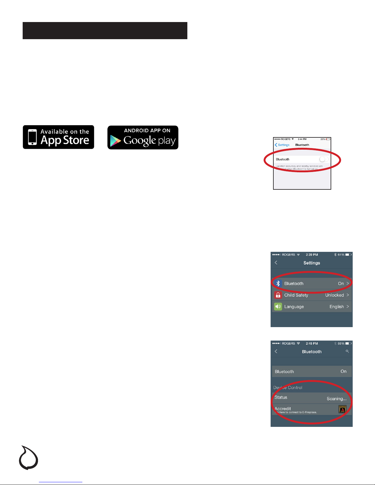
1. DOWNLOAD THE APP FROM YOUR MOBILE PLATFORM APP STORE
Search for “BluetoothFireplace” and download our free Bluetooth™ enabled remote app
within your mobile device’s preferred app store.
2. BE SURE TO ACTIVATE BLUETOOTH™ ON YOUR PHONE
Open your “settings” on your phone and select Bluetooth™. Tap to activate
Bluetooth™ connectivity on your phone.
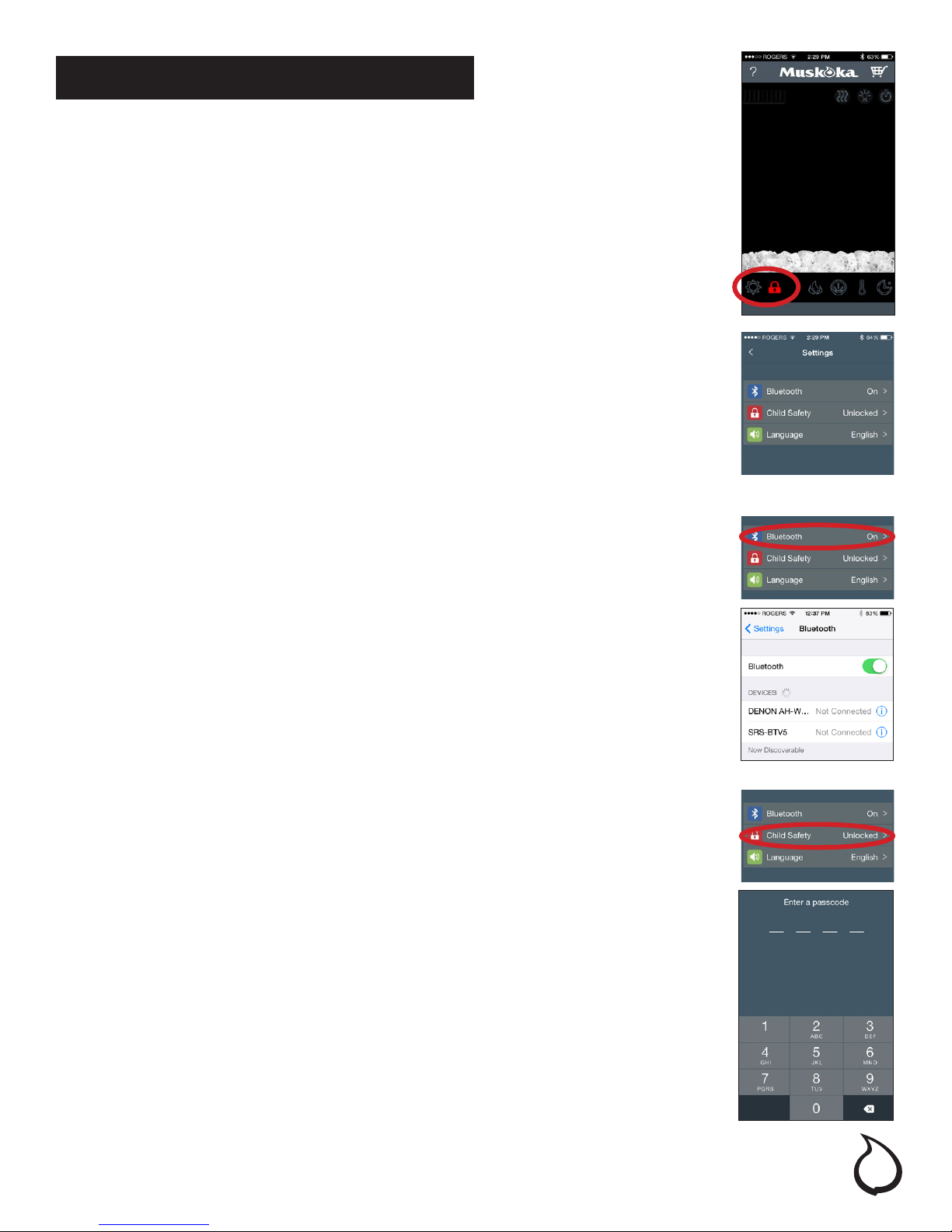
3. TURN ON YOUR FIREBOX
Press the main power button (1) on the rebox touchscreen control panel to activate the rebox.
4. TURN ON YOUR MOBILE APP
Tap the remote app icon on your mobile device to activate the app.
5. ESTABLISH A CONNECTION TO THE FIREBOX
Tap the <settings> icon to access the app settings. Tap the
<Bluetooth™> menu to access the Bluetooth™ connection screen. The
mobile device will automatically detect the Bluetooth™ enabled rebox
in your immediate vicinity.
6.VERIFY THE CONNECTION TO THE FIREBOX
Tap <Accredit> to very the connection between your mobile device
and the rebox. This will allow your mobile device to automatically
reconnect to your rebox in the future - even if the remote app has been
previously deactivated.
YOUR REMOTE APP IS NOW CONNECTED TO THE FIREBOX
10

Operation (continued)
The following instructions iluustrate the operation of the mobile remopte control app once it has been installed on
your mobile device. If the app has not yet been installed please read through and follow the instructions on the
previous page.
If at any point you’d like to see the tutorial screens in the app - simply tap the question mark icon in the upper
left hand corner of the screen.
1. ACTIVATE THE APP
Tap the app icon on your mobile device to activate the app.
2. ACTIVATE THE FIREBOX
Tap the power icon in the upper right hand corner to activate the rebox. The
heat, ame and ember bed images displayed reect the selected settings on
the rebox in your room.
2.
3. COLOR CHANGING EFFECTS
Tap the ame and ember bed images or their icons along the bottom to change
their color settings. Choose from Orange, Blue, Orange and Blue and Color
Rotation. The images change to reect the settings on made to the rebox.
4. FLAME BRIGHTNESS SETTINGS
Tap the lightbulb icon in the upper right hand side to change the ame
brightness settings. Choose from high, medium, and low brightness. The ame
image’s height reects the change to the brightness settings.
3.
4.
11

Operation (continued)
5. HEAT SETTINGS (HEAT-OFF)
Heat-off is the default when rebox is rst activated, the heat is in the status of
off, the heat vent shown in the upper left hand side won’t illuminate to show
there is no heat output.
5.
6. HEAT SETTINGS (HEAT-ON)
Heat is in the state of on, the heat vent shown in the upper left hand side will fully
illuminate to show there is heat output.
7. THERMOSTAT CONTROL
Tap the thermometer icon to reveal the thermostat indicator. Tap the icon to
increase/decrease the thermostat settings. The heat display will change to
display the selected temperature. When the thermometer icon is released, the
icon and the digital display will return to their original position To change the
display from ˚F to ˚C, simply tap and hold the thermostat icon for 5 seconds.
6.
7.
8. TIMER CONTROL
Tap the stopwatch icon to reveal the timer indicator. Tap the icon to increase
the timer settings. When the icon is released, the icon and the digital display will
return to their original positions.
12
8.
Operation (continued)
9. ADJUST THE APP SETTINGS
Tap the gear icon to access the app settings screen. Note - The Child Safety
Lock icon is only visible next to the settings icon when the safety lock has been
engaged.
9.
10. MAIN SETTINGS SCREEN
From this screen you can connect the app to the Bluetooth™
activated rebox, engage the no-heat-child safety lock, and adjust the app’s
language settings.
11. BLUETOOTH SCREEN
As indicated in the previous pages in this manual - From this screen you can
connect the app to the bluetooth activated rebox, simply activate the rebox’s
bluetooth pairing mode and tap the rebox when it appears in the “devices” list.
10.
11.
12. CHILD SAFETY LOCK FEATURE
From this screen you can engage the child safety lock to prevent the heater
from being activated or the internet being accessed without rst entering a 4
digit code. When activated a red lock is visible from the main screen next to the
settings icon. To activate the lock enter any 4 digit code of your choice. The app
will remeber this code until the next time you enter it to deactivate the child lock
function.
12.
13

Operation (continued)
13. LANGUAGES
From this screen you can switch between the app’s available languages
(English, French, and Spanish).
14. SHOP ONLINE
Tap the shopping cart icon in the upper right hand side of the main screen.
When NOT in child lock mode) the user’s mobile device will direct the preferred
web browsing app to the GHP Group inc. online store landing page.
13.
14.
15. THE “WHAT’S NEW” BAR
Swipe up from the bottom to reveal the what’s new bar. It shows links to the
latest products, blog posts, twitter feed, and our other social media connections
/ promotional items.
15.
14
Maintenance
DANGER: Disconnect power before servicing.
WARNING: Any electrical re-wiring of this appliance must be done by a qualied electrician. This
wiring must be done in accordance with local codes and/or in Canada with the current CSA C22.1
Canadian Electrical Code, and for US installations, the National Electrical Code ANSI/NFPA NO 70.
WARNING: If repairing or replacing any electrical component or wiring, the original wire routing, color
coding and securing locations must be followed.
GLASS INFORMATION
1. Under no circumstances should this product be operated with a broken or chipped glass panel.
2. Do not strike or slam the glass.
3. Do not use abrasive cleansers to clean the glass. Make sure the glass is cool to the touch.
4. This product uses tempered glass. Replacement of the glass supplied by the manufacturer should be done
by qualied/authorized service personnel only.
MAINTENANCE OF MOTORS
1. Always disconnect the appliance from the main power supply and allow it to cool before any servicing
operation.
2. The motors used on the fan heater and ame blower are pre-lubricated for extended bearing life and
require no further lubrication. However, periodic cleaning/vacuuming of the appliance around the air
intake and exhaust, as well as the fan heater is reccomended. For heavy or continous use, periodic
cleaning must be done more frequently. If the heater blows alternating cold and warm air, check the fan
for free movement and for debris restricting air ow. If the fan does not move freely, the unit be turned off
and fan replaced immiediately in order to prevent further damage to the unit.
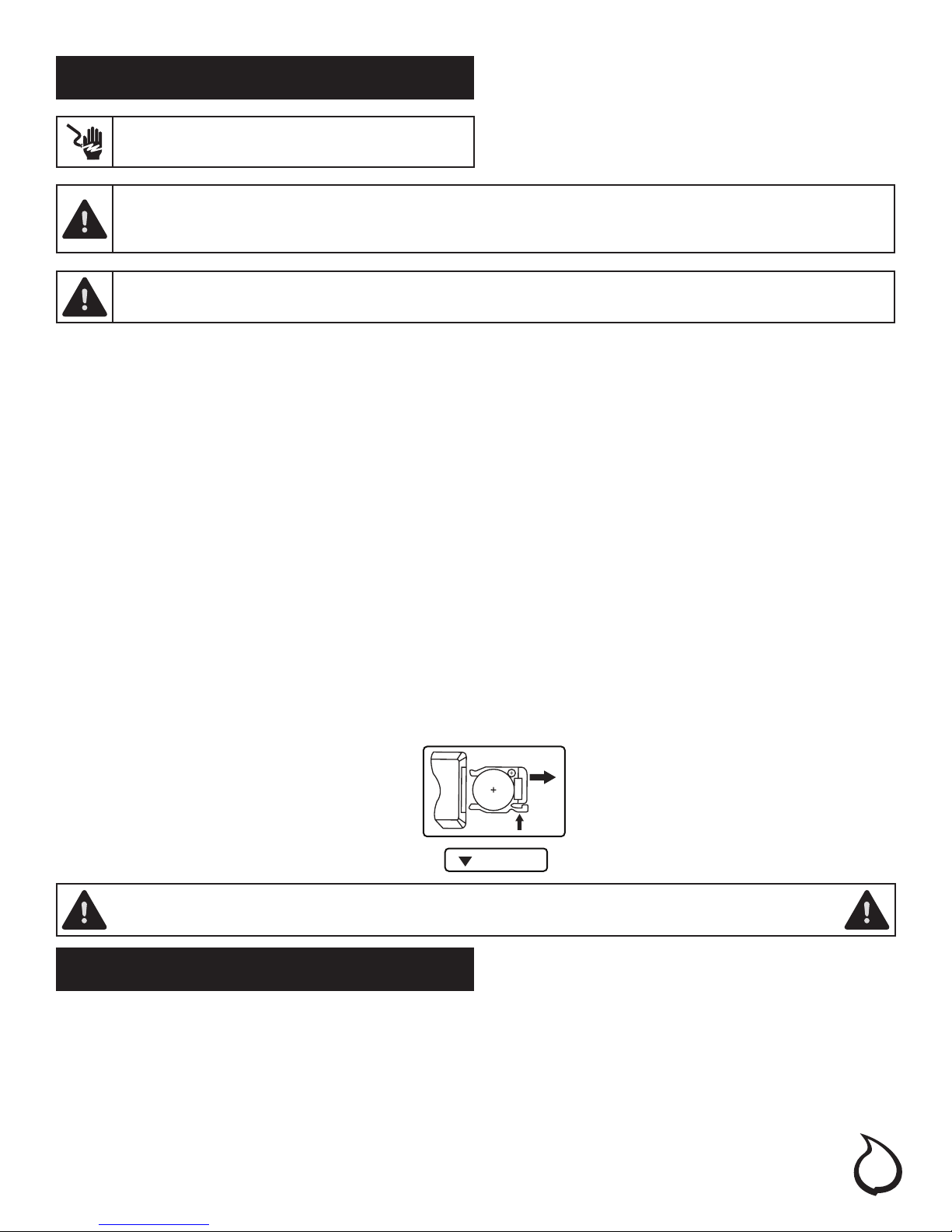
BATTERY REPLACEMENT
Please dispose of the used battery per municipal or provincial/state law.
CR2025
Battery Replacement Procedure: (Size CR2025)
RELEASE
THIS PRODUCT CONTAINS BATTERIES. IF SWALLOWED, IT COULD CAUSE SEVERE INJURY OR DEATH
IN JUST 2 HOURS. SEEK MEDICAL ATTENTION IMMEDIATELY.
OPEN
PUSH
Care and Cleaning
1. Always turn the heater OFF and unplug the power cord from the outlet before cleaning.
2. Cleaning of the control panel, located in the upper right-hand corner of the replace, is to be done only
using a soft cloth, slightly dampened in water (if needed, a small amount of dish soap can be added to
the water) and dried using a clean, dry soft cloth. Cleaning of the screen diffuser is to be done using only
water and lint free cloth. DO NOT use any abrasive on the controls or the diffusing screen.
15
 Loading...