

Muskoka 37-196-48, 37-196-204 Use And Care Manual
ELECTRIC FIREPLACE MEDIA MANTEL
USE AND CARE GUIDE | GUIDE D’UTILISATION ET D’ENTRETIEN
FOYER ÉLECTRIQUE AVEC MANTEAU
POUR APPAREILS ÉLECTRONIQUES
IMPORTANT:
SAVE THESE
INSTRUCTIONS.
PLEASE READ THIS MANUAL BEFORE
INSTALLING AND USING APPLIANCE
IF THE INFORMATION IN THIS MANUAL IS NOT FOLLOWED
EXACTLY, AN ELECTRICAL SHOCK OR FIRE MAY RESULT
CAUSING PROPERTY DAMAGE, PERSONAL INJURY OR LOSS OF LIFE.
Retain this manual for future use.
WARNING!
37-196-48 / 37-196-204
IMPORTANT :
CONSERVER CES
INSTRUCTIONS.
VEUILLEZ LIRE CE MANUEL AVANT L’INSTALLATION
ET L’UTILISATION DE VOTRE FOYER
SI LES RENSEIGNEMENTS DE CE MANUEL NE SONT PAS EXACTEMENT
SUIVIS, UN CHOC ÉLECTRIQUE OU UN INCENDIE PEUT SURVENIR, ET
CAUSER DES DOMMAGES, DES BLESSURES OU LA PERTE DE VIE
Conserver ce manuel pour une utilisation ultérieure.
AVERTISSEMENT!
Français p. 17 20-10-306

Table of Contents
Table of Contents ...........................2
Warranty ...................................2
Pre-Assembly ...............................3
Planning Assembly ......................... 3
Tools Required. . . . . . . . . . . . . . . . . . . . . . . . . . . . . 3
Hardware Included ........................ 3
Package Contents .........................4
Assembly .................................. 5
Troubleshooting ............................ 14
Care and Cleaning. . . . . . . . . . . . . . . . . . . . . . . . . 15
Shelf Weight Capacity ......................15
Service Parts ...............................15
1 Year Warranty
WHAT IS COVERED
The manufacturer warrants that your new electric replace is free from manufacturing and material defects for
a period of one year from date of purchase, subject to the following conditions and limitations.
This electric replace must be installed and operated at all times in accordance with the instructions furnished
with the product. Any alteration, willful abuse, accident, or misuse of the product shall nullify this warranty.
This warranty is non-transferrable, and is made to the original owner, provided that the purchase was made
through an authorized supplier of the manufacturer. This warranty is limited to the repair or replacement of
part(s) found to be defective in material or workmanship, provided that such part(s) have been subjected
to normal conditions of use and service, after said defect is conrmed by the manufacturer’s inspection. The
manufacturer may, at its discretion, fully discharge all obligations with respect to this warranty by refunding the
wholesale price of the defective part(s).
WHAT IS NOT COVERED
Any installation, labor, construction, transportation, or other related costs/expenses arising from defective
part(s), repair, replacement, or otherwise of same, will not be covered by this warranty, nor shall the
manufacturer assume responsibility for same. Further, the manufacturer will not be responsible for any
incidental, indirect, or consequential damages, except as provided by law.
All other warranties - expressed or implied - with respect to the product, its components and accessories, or any
obligations/liabilities on the part of the manufacturer are hereby expressly excluded. The manufacturer neither
assumes, nor authorizes any third party to assume, on its behalf, any other liabilities with respect to the sale of
this product. The warranties as outlined within this document do not apply to non-manufacturer accessories
used in conjunction with the installation of this product.
This warranty does not cover the lightbulb(s) included with the replace.
This warranty is void if: the replace has been operated in atmospheres contaminated by chlorine, uorine, or
other damaging chemicals; the replace is subjected to prolonged periods of dampness or condensation; the
replace is altered, willfully abused, damaged by accident, or misused in any way.
If warranty service is needed, contact the Customer Service Team at 1-800-986-3460 from 8 a.m. - 6 p.m., EST,
Monday-Friday or visit www.homedepot.com/hdc.
Make sure you have your warranty, your sales receipt, and the model/serial number of your product.
DO NOT ATTEMPT TO DO ANY SERVICE WORK YOURSELF. PLEASE CONTACT CUSTOMER SERVICE AT:
1-877-447-4768 Monday to Friday from 8:30AM to 4:30PM (EST),
Web: www.ghpgroupinc.com
Email: customerservice@ghpgroupinc.com
Canada: 271 Massey Road, Guelph, Ontario, Canada, N1K 1B2
USA: 6440 W. Howard Street, Niles, Illinois U.S.A. 60714
2
Pre-Assembly
PLANNING ASSEMBLY
Before you begin assembly, locate the instructions and hardware. Compare all parts with the Hardware
Included and Package Contents lists. Be sure you have all the parts and can identify them. A helping hand is
always good. Assemble your mantel with an adult assistant if possible. Some pieces are heavy and will need to
be held by a helper. Assembly time will take approximately 30-60 minutes.
Before assembly, use scissors to unwrap the parts from the packaging. Do not use a box cutter or exacto-knife,
as you may cut into the mantel pieces inside the box and damage the nish. Check for the red hardware bag
located inside the packaging. Do not discard any pieces. Use an appropriate screwdriver to insert and tighten
all screws.
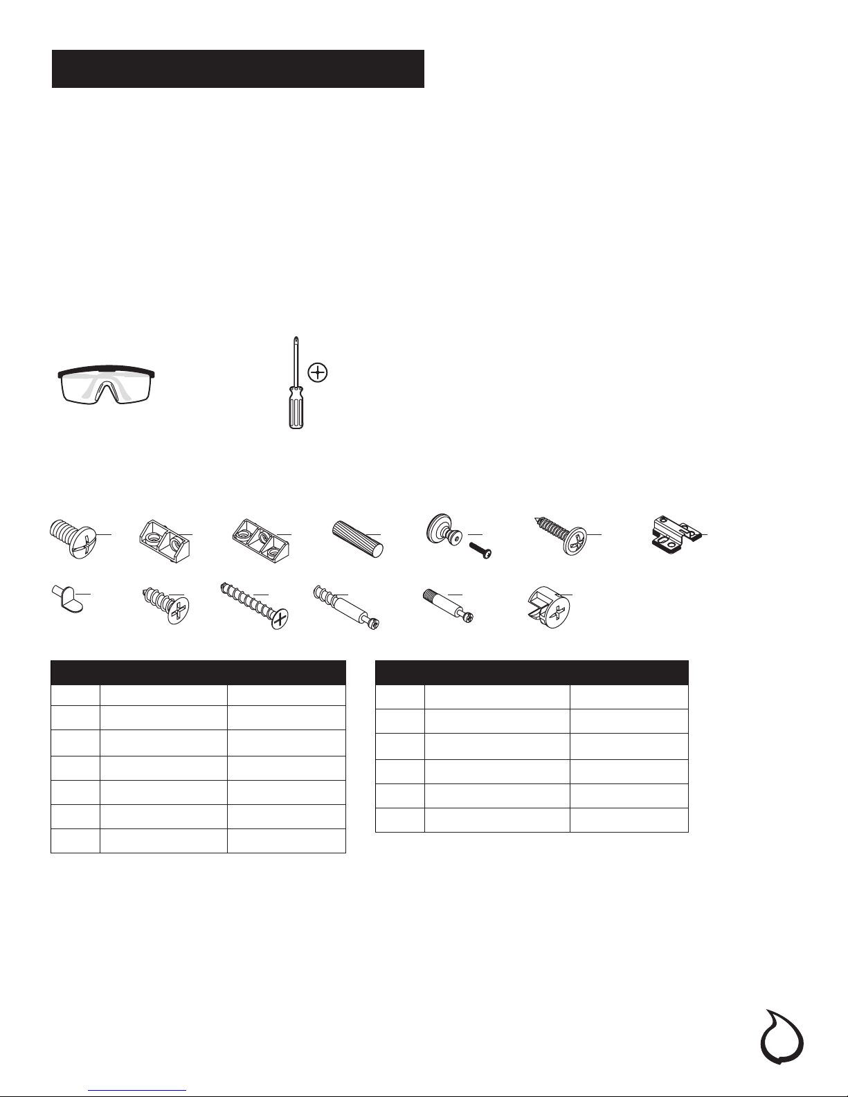
TOOLS REQUIRED (NOT INCLUDED)
Safety
goggles
HARWARE INCLUDED
Note: Hardware not shown to actual size.
AA
HH
Part Description Quantity
AA Bolt 33
BB Short Connector 2
CC Long Connector 2
DD Dowel 36
EE Knob 2
FF Back Panel Screw 30
GG Door Hinge Plate 4
BB
JJ
CC
KK
Phillips
screwdriver
DD
LL
Part Description Quantity
HH Shelf Pin 8
JJ Hinge Screw 16
KK Long Screw 2
LL Long Metal Bolt 4
MM Short Metal Bolt 4
NN Metal Cam Lock 8
MM
GGFFEE
NN
3
Pre-Assembly (continued)
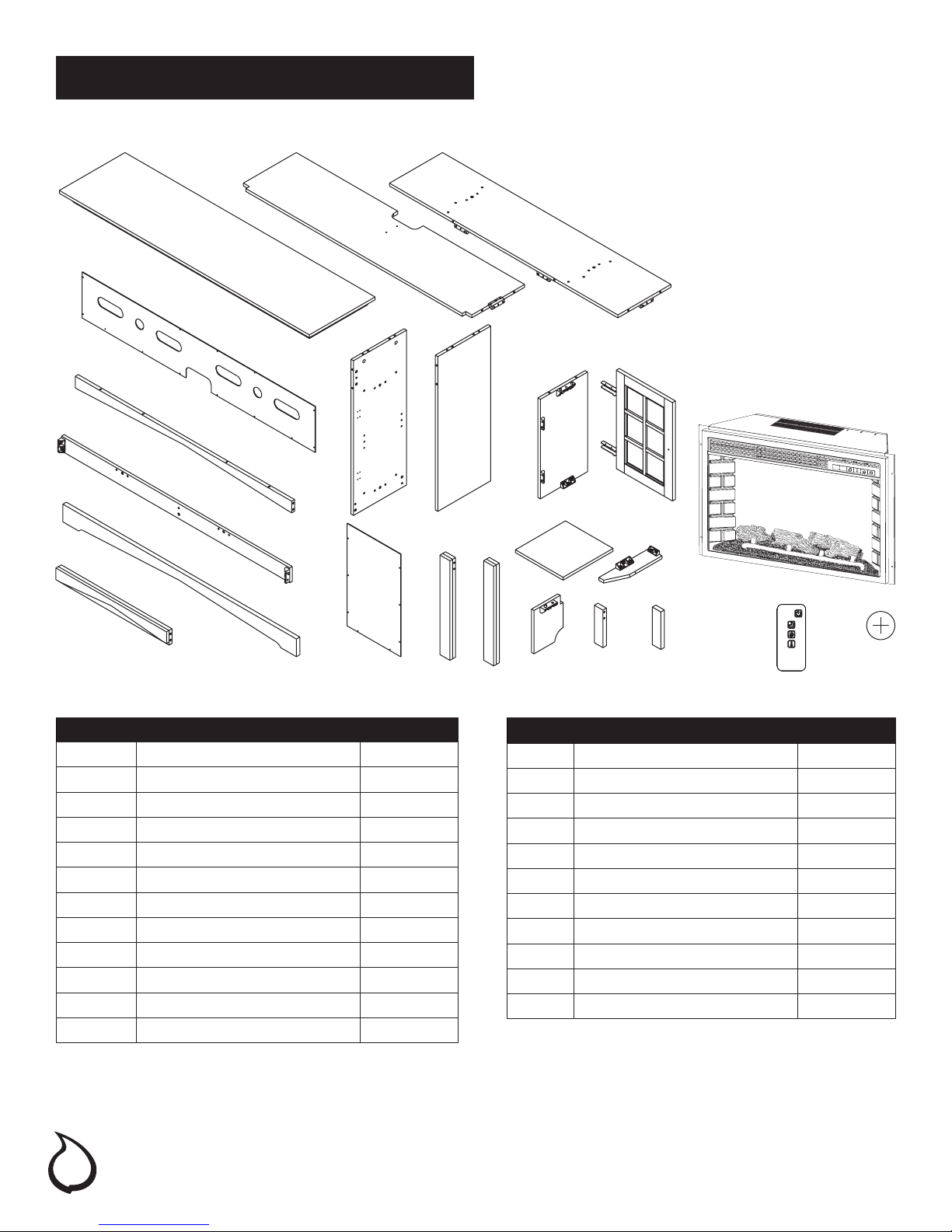
PACKAGE CONTENTS
M
J
K
L
D
A
B
E
F
N P Q
C
W
G
H
R
V
YX
S T U
Part Description Quantity
A Top Panel 1
B Media Shelf 1
C Base Panel 1
D Upper Back Panel 1
E Left Side Panel 1
F Right Side Panel 1
G Inside Panel 2
H Cabinet Door 2
J Top Rail 1
K Rear Apron Panel 1
L Front Apron Panel 1
M Top Trim 1
4
Part Description Quantity
N Side Back Panel 2
P Left Trim 1
Q Right Trim 1
R Adjustable Shelf 2
S Support Panel 1
T Left Front Panel 1
U Right Front Panel 1
V Support Leg 1
W Firebox 1
X Firebox Remote Control 1
Y Button Cell Battery 1

Assembly
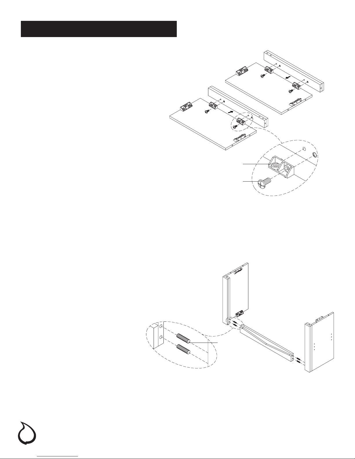
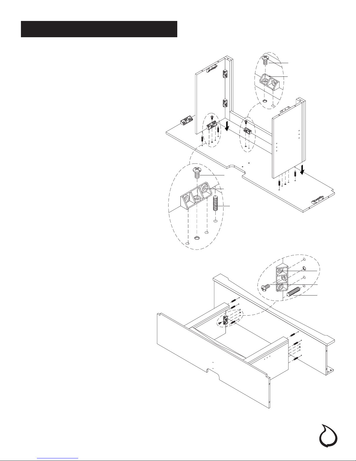
ATTACHING THE SUPPORT
LEG AND CONNECTORS
1. Locate the base panel (C) and place on a
soft surface to protect the nish. Line up and
insert the long connector (CC) on the support
leg (V) into the unthreaded holes in the
center of the base panel (C).
2. Attach the support leg (V) to the base panel
(C) by turning a bolt (AA) clockwise through
the long connector (CC). Do not strip the
bolt (AA) by overtightening.
3. Locate the top trim (M) and place them on a
soft surface to protect the nish.
4. Insert two short connectors (BB) into the top
trim (M) where indicated. Press down rmly
until ush.
5. Attach the short connectors (BB) by inserting
two bolts (AA) and turning clockwise. Do not
strip the bolts (AA) by overtightening.
V
C
AA
CC
AA
BB
M
ATTACHING THE FRONT AND BACK
PANELS TO THE BASE
1. Line up and insert two wood dowels (DD) into
the unthreaded holes in the side of the base
panel (C). Line up the wood dowels (DD) with
the unthreaded holes in the front apron panel
(L). Press together until ush.
2. Line up the short and long connectors (BB
& CC) in the base assembly (C) with the
unthreaded holes in the rear apron panel (K).
Press together until ush.
3. Insert ve bolts (AA) into the short and long
connectors (BB & CC) on the base assembly.
4. Attach the front and rear apron panels (L &
K) by turning the bolts (AA) clockwise. Do not
strip the bolts (AA) by overtightening.
BB
AA
K
C
L
AA
CC
DD
5
Assembly (continued)
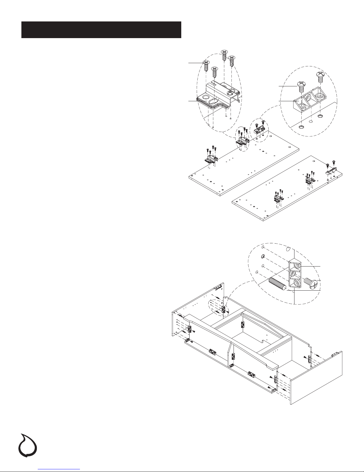
ATTACHING THE LEFT
AND RIGHT TRIM PIECES
1. Line up the short connectors (BB) in the inner
panels (G) with the unthreaded holes in the left
and right trim pieces (P & Q). Press together until
ush.
2. Insert four bolts (AA) into the short connectors
(BB) on the inner panels where indicated.
3. Attach the left and right trim pieces (P & Q) by
turning the bolts (AA) clockwise. Do not strip the
bolts (AA) by overtightening.
Q
P
G
G
BB
AA
ATTACHING THE INNER PANELS
1. Insert four wood dowels (DD) into the
unthreaded holes in the top trim (M).
2. Line up the four wood dowels (DD) in the top
trim (M) with the unthreaded holes in the left and
right trim pieces (P & Q).
3. Press together rmly until ush.
Q
DD
G
M
P
G
6
Assembly (continued)
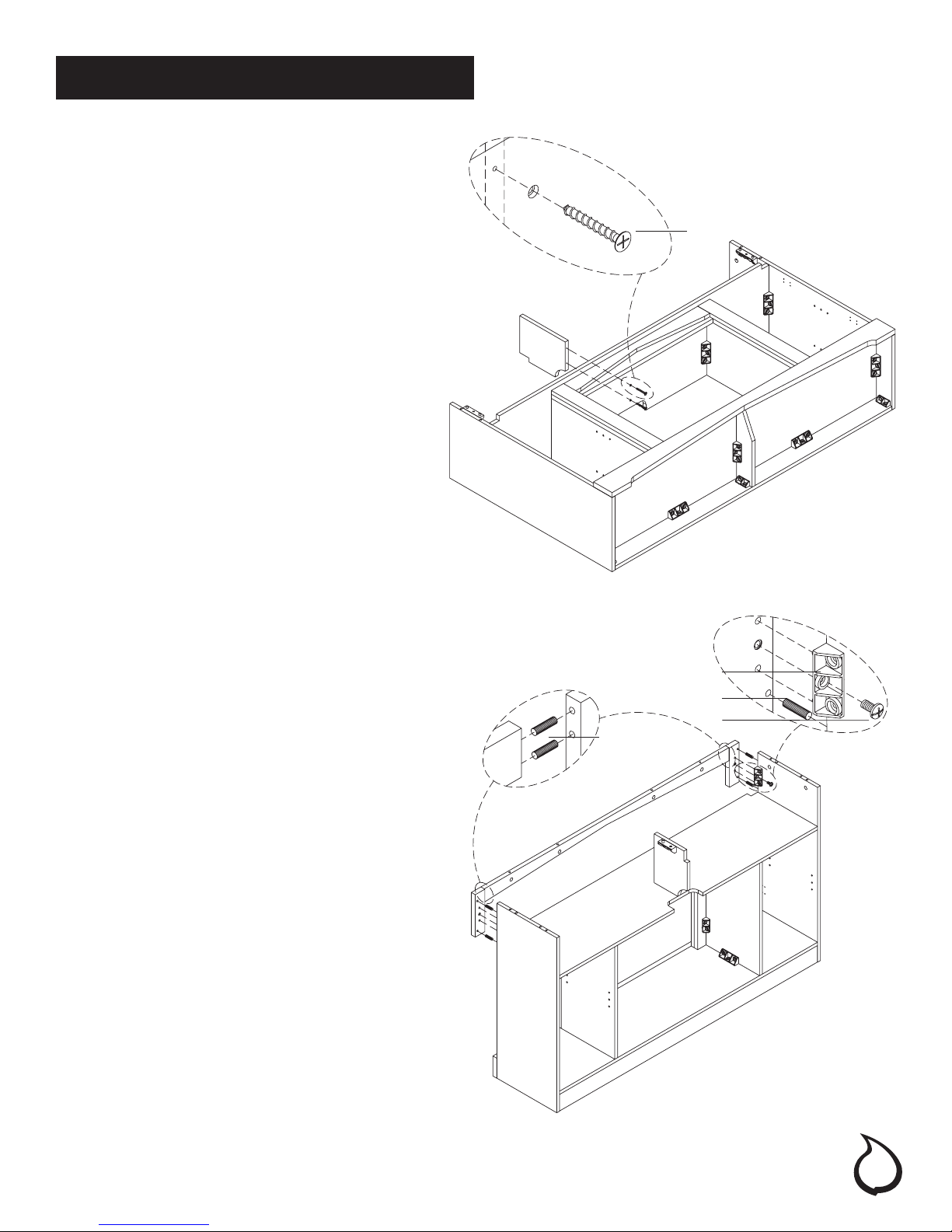
ATTACHING THE MEDIA SHELF
1. Insert four wood dowels (DD) in the
unthreaded holes of the media shelf (B).
2. Line up the wood dowels (DD) in the media
shelf (B) with the unthreaded holes in the
left and right inner panels (G).
3. Line up the short and long connectors
(BB & CC) attached to the inner panel
assembly with the holes in the media shelf
(B).
4. Press the inner panel assembly down rmly
onto the media shelf until ush.
5. Insert four bolts (AA) into the short and long
connectors
(BB & CC) on the inner panel assembly.
6. Attach the inner panel assembly to the
media shelf (B) by turning the bolts (AA)
clockwise. Do not strip the bolts (AA) by
overtightening.
AA
BB
G
M
G
B
AA
CC
DD
ATTACHING THE BASE
1. Insert six wood dowels (DD) into the
unthreaded holes in the media shelf
assembly.
2. Line up the wood dowels (DD) with the
unthreaded holes in the base panel (C).
Press together rmly until ush.
3. Attach the base panel (C) to the media
shelf assembly by inserting two bolts (AA)
through the long connectors (CC) on the
inner panels (G) and turning clockwise. Do
not strip the bolts (AA) by overtightening.
G
B
CC
AA
DD
C
G
7
Assembly (continued)
ATTACHING HARDWARE
ONTO THE SIDE PANELS
1. Locate the left and right side panels (E & F)
and place them on a soft surface to protect
the nish.
JJ
AA
2. Insert long connectors (CC) into the left and
right side panels (E & F) where indicated.
Press down rmly until ush.
3. Attach the long connectors (CC) by
inserting and turning four bolts (AA)
clockwise. Do not strip the bolts (AA) by
overtightening.
4. Attach the four door hinge plates (GG)
to the left and right side panels (F & F) by
inserting and tightening sixteen hinge screws
(JJ). Do not overtighten and strip the hinge
screws (JJ).
ATTACHING THE SIDE PANELS
1. Insert eight wood dowels (DD) into the
unthreaded holes in the sides of the media
shelf (B) and the base panel (C).
GG CC
E
F
CC
2. Line up the wood dowels (DD) in the sides
of the media shelf (B) and the base panel
(C) with the unthreaded holes in the left
and right side panels (E & F).
3. Line up the long connectors (CC) in the
media shelf (B) and the base panel (C)
with the holes in the left and right side
panels (E & F).
4. Press the left and right side panels (E & F)
rmly until ush with the media console
assembly.
5. Attach the left and right side panels to the
media console assembly by inserting eight
bolts (AA) through the long connectors
(CC) in the media shelf (B) and the base
panel (C) and turning clockwise. Do not
strip the bolts (AA) by overtightening.
8
AA
DD
E
B
C
F
Assembly (continued)
ATTACHING THE SUPPORT PANEL
1. Attach the support panel (S) to the media
shelf (B) by lining up the holes in the bottom
of the support panel (S) with the holes in the
media shelf (B). Insert and tighten two screws
(KK) through the media shelf (B) into the
support panel (S).
2. Do not strip the screws (KK) by overtightening.
KK
S
B
C
E
ATTACHING THE TOP RAIL
1. Insert four wood dowels (DD) into the
unthreaded holes in the sides of the top rail (J).
2. Line up the wood dowels (DD) in the top rail (J)
with the unthreaded holes in the sides of the
left and right front panels (T & U). Press together
rmly until ush.
3. Insert 4 wood dowels (DD) into the unthreaded
holes on the back of the left and right front
panels (T & U).
4. Line up the wood dowels (DD) in the left and
right front panels (T & U) with the unthreaded
holes in the left and right side panels (E & F).
5. Line up the long connectors (CC) in the left
and right side panels (E & F) with the holes
in the left and right front panels (T & U). Press
together rmly until ush.
6. Attach the top rail assembly to the left and
right side panels (E & F) by inserting two bolts
(AA) through the long connectors (CC) in the
left and right side panels (E & F) and turning
clockwise. Do not strip the bolts (AA) by
overtightening.
U
F
B
DD
J
CC
DD
AA
T
E
9
 Loading...