

Muskoka 310-42-45 User Manual

Electric Fireplace
107 cm / 42 in
Foyer électrique mural courbé de
107 cm / 42 po
Chiminea eléctrica de
107 cm / 42 pulg
Important:
Retain for future reference:
Read carefully
Important :
Conserver pour référence
ultérieure : lire attentivement
Importante:
Conserve para referencias futuras:
Lea cuidadosamente antes de usar
218326
Model/Modèle/Modelo : 310-42-45- Brand/Marque : MUSKOKA®
Français p. 17
Español p. 32
2017-04-0620-10-305

Table of Contents
Table of Contents ...................................2
Safety Information ..................................2
Warranty ..........................................3
Pre-Installation .....................................4
Installation - Wall-Mount .............................8
Safety Information
Retain for future reference: Read carefully
1. Read all instructions before using this replace.
2. Always unplug this appliance when not in use.
3. Children should be advised not to play with this replace.
4. Do not operate any heater with a damaged cord or plug or after
the heater malfunctions, has been dropped or damaged
in any manner. Return heater to authorized service facility for
examination, electrical or mechanical adjustment, or repair.
5. Any repairs to this appliance should be carried out by
qualied/authorized service personnel only.
6. Under no circumstances should this appliance be modied.
Parts having to be removed for servicing must be replaced
with original “OEM” (original equipment manufacturers) parts
only.
7. Do not use outdoors.
8. This appliance is not intended for use in bathrooms, laundry
areas, and similar indoor locations. Never locate this appliance
where it may fall into a bathtub or other water container.
9. Do not run the cord under carpeting. Do not cover the cord with
throw rugs, runners, or the like. Arrange the cord away from
trafc areas and where it will not be tripped over.
10. To disconnect heater, turn controls to off, then remove plug
from outlet.
11. Connect to properly grounded outlets only.
12. This appliance, when installed, must be electrically grounded
in accordance with local codes, with the current CSA C22.1
Canadian Electric codes, or for USA installations, follow local
codes and the National Electrical Code, ANSI/NFPA No. 70.
13. There is a thermostat limiter inside the replace. When the
inner temperature over heats or abnormal heating occurs, the
thermostat protective device will cut off power supply to avoid
damage to the replace or risk of re.
14. This appliance has hot and arching or sparking parts inside.
Do not use it in areas where gasoline, paint, or ammable
liquids are used or stored. This appliance should not be used
as a drying rack for clothing, nor should Christmas stockings
or decorations be hung on or near it.
15. Use this appliance only as described in this manual. Any other
use not recommended by the manufacturer may cause re,
electric shock, or injury to persons.
16. The use of an extension cord is not recommended due risk of
re. If used the extension cord shall be No. 14 AWG minimum
size and rated no less than 1875 watts, and the extension cord
2
Installation - Table Top ...............................9
Operation. . . . . . . . . . . . . . . . . . . . . . . . . . . . . . . . . . . . . . . . . 11
Care and Cleaning .................................14
Maintenance ......................................15
Service Parts ......................................16
shall be a three-wire cord with grounding type plug and cord
connector. The extension cord shall not be more than 20 ft (6 m)
in length.
17. Do not use this appliance with a programmable timer or any other
device that switches the appliance on and off automatically. In
order to avoid a hazard due to inadvertent resetting of the thermal
cut out, this appliance must not be supplied through an external
switching device, such as a timer, or connected to a circuit that is
regularly switched on and off by an utility.
18. This product contains a button battery. If swallowed, it could
cause severe injury or death in just 2 hours. Seek medical
attention immediately.
CAUTION: Operate only on supplied stand or mounted
to wall.
WARNING: This heater is hot when in use. To avoid
burns, do not let bare skin touch hot surfaces. If provided,
use handles when moving this appliance. Keep combustible
materials, such as furniture, pillows, bedding, papers,
clothes, and curtains at least 3 feet (0.9 m) from front, sides
and rear of the heater.
CAUTION: When using electrical appliances, basic
precautions should always be followed to reduce the risk of
re, electrical shock, and injury to persons.
CAUTION: To prevent a possible re, do not block heater
air intakes or the exhaust in any manner. Do not operate
the heater on soft surfaces, like a bed, where openings may
become blocked.
CAUTION: Do not insert or allow foreign objects to enter
any ventilation or exhaust openings, as this may cause an
electric shock or re, or damage to the heater.
CAUTION: Extreme caution is necessary when any
heater is used by or near children or invalids, and whenever
the heater is left operating and unattended.
IMPORTANT: SAVE THESE
INSTRUCTIONS.
1 YEAR WARRANTY
WHAT IS COVERED
The manufacturer warrants that your new electric replace is free from manufacturing and material defects for a period of one year from date
of purchase, subject to the following conditions and limitations.
This electric replace must be installed and operated at all times in accordance with the instructions furnished with the product. Any alteration,
willful abuse, accident, or misuse of the product shall nullify this warranty. This warranty is non-transferrable, and is made to the original
owner, provided that the purchase was made through an authorized supplier of the manufacturer.This warranty is limited to the repair or
replacement of part(s) found to be defective in material or workmanship, provided that such part(s) have been subjected to normal conditions
of use and service, after said defect is conrmed by the manufacturer’s inspection. The manufacturer may, at its discretion, fully discharge all
obligations with respect to this warranty by refunding the wholesale price of the defective part(s).
WHAT IS NOT COVERED
Any installation, labor, construction, transportation, or other related costs/expenses arising from defective part(s), repair, replacement, or
otherwise of same, will not be covered by this warranty, nor shall the manufacturer assume responsibility for same. Further, the manufacturer
will not be responsible for any incidental, indirect, or consequential damages, except as provided by law.
All other warranties - expressed or implied - with respect to the product, its components and accessories, or any obligations/liabilities on
the part of the manufacturer are hereby expressly excluded. The manufacturer neither assumes, nor authorizes any third party to assume,
on its behalf, any other liabilities with respect to the sale of this product. The warranties as outlined within this document do not apply to
nonmanufacturer accessories used in conjunction with the installation of this product.
This warranty does not cover the light bulb(s) included with the replace.
This warranty is void if: the replace has been operated in atmospheres contaminated by chlorine, uorine, or other damaging chemicals; the
replace is subjected to prolonged periods of dampness or condensation; the replace is altered, willfully abused, damaged by accident, or
misused in any way.
Make sure you have your warranty, your sales receipt, and the model/serial number of your product.
Our goods come with a guarantee that cannot be excluded under the Australian Consumer Law. You are entitled to a replacement or
refund for a major failure and for compensation for any other reasonably foreseeable loss or damage. You are also entitled to have the
goods repaired or replaced if the goods fail to be of acceptable quality and the failure does not amount to a major failure.
DO NOT ATTEMPT TO DO ANY SERVICE WORK YOURSELF. PLEASE CONTACT CUSTOMER SERVICE AT:
1-877-447-4768 Monday to Friday from 8:30AM to 4:30PM (EST),
Web: www.ghpgroupinc.com
Email: customerservice@ghpgroupinc.com
Canada: 271 Massey Road, Guelph, Ontario, Canada, N1K 1B2
USA: 6440 W. Howard Street, Niles, Illinois U.S.A. 60714
3
Pre-Installation
PLANNING INSTALLATION
Before you begin assembly, locate the instructions and hardware. Compare all parts with the Hardware Included and Package Contents lists.
Be sure you have all the parts and can identify them. A helping hand is always good. Assemble your replace with an adult assistant if
possible. Some pieces are heavy and will need to be held by a helper. Assembly time will take approximately 5-20 minutes.
Before assembly, use scissors to unwrap the parts from the packaging. Do not use a box cutter or exacto-knife, as you may cut into the
heater pieces inside the box and damage the nish. Check for the red hardware bag located inside the packaging, taped to the top of the
box. Do not discard any pieces. Use an appropriate screwdriver to insert and tighten all screws.
CAUTION: This carton includes a GLASS panel! Always use extreme caution when handling glass. Failure to do so could result in personal
injury or property damage.
SPECIFICATIONS
Model No. 310-42-45
Wall Mounted Dimensions W x D x H 107 cm x 11 cm x 44 cm (42 in x 4.3 in x 17.3 in)
Stand Mounted Dimensions W x D x H 107 cm x 22.2 cm x 54.1 cm (42 in x 8.7 in x 21.3 in)
Net Weight / Gross Weight 17.8 kg / 20.8 kg (39.2 lb x 45.8 lb)
Voltage 120V
Frequency 60 Hz
Watts / Amps 1400 W / 11.7 A
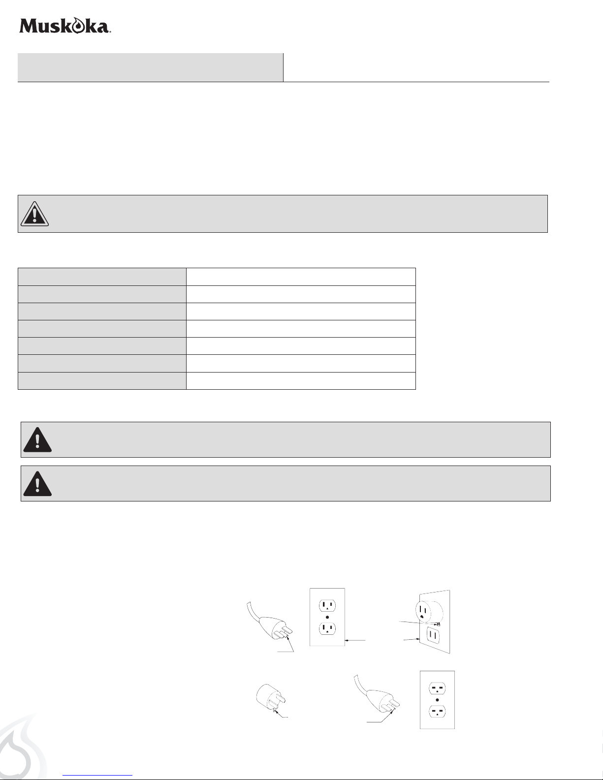
ELECTRICAL CONNECTION
WARNING: Electrical outlet wiring must comply with local building codes and other applicable regulations to reduce the risk of re,
electrical shock, and injury to persons.
WARNING: Do not use this replace if any part of it has been under water. Immediately call a qualied service technician to inspect the
replace and replace any part of the electrical system which has been under water.
A 15 Amp, 120 Volt, 60 Hz circuit with a properly grounded outlet is required to operate this appliance. Preferably, the appliance will be on a
dedicated circuit, as other appliances on the same circuit may cause the circuit breaker to trip or the fuse to blow when the replace is in
operation. The unit comes standard with a 6 ft (1.8 m) long 3-wire cord, exiting out the back of the replace. Plan the installation to avoid
the use of an extension cord. If an extension cord must be used, it must be a minimum No. 14 AWG, 3-wire with grounding type plug and
connector, and must be rated not less than 1875 watts. The extension cord shall not be more than 20 ft (6 m) in length.
Figure 1
GROUNDING INSTRUCTIONS
This heater is for use with 120 volts. The cord has
a plug as shown at (A) in Figure 1. An adapter as
shown at (C) is available for connecting three-blade
grounding-type plugs to two-slot receptacles. The
green grounding lug extending from the adapter
must be connected to a permanent ground such as
a properly grounded outlet box. The adapter should
not be used if a three-slot grounded receptacle is
available.
4
GROUNDING
(C)
PIN
(A)
ADAPTER
GROUNDING
MEANS
METAL SCREW
COVER OF GROUNDED
GROUNDING
PIN
OUTLET BOX
(B)
(D)
NOTE: Adapters are NOT
for use in Canada.
Remote Control
This Class (B) device complies with Part 15 of the FCC Rules and Canadian ICES-003. Operation is subject to the following two conditions:
(1) This device may not cause harmful interference, and (2) this device must accept any interference received, including interference that
may cause undesired operation. There is no guarantee that interference will not occur in a particular installation. If this equipment does
cause harmful interference to radio or television reception, which can be determined by turning the equipment off and on, the user is
encouraged to try to correct the interference by one ore more of the following measures:
• Reorient or relocate the receiving antenna.
• Increase the separation between the equipment and receiver.
• Connect the equipment into an outlet on a circuit different from that to which the receiver is connected.
• Consult the dealer or an experienced radio/TV technician for help.
This remote control requires 1 Lithium Coin Cell Battery (size CR2025), which is included.
CAUTION: Changes or modications to this unit not expressly approved by the party responsible for compliance could void the user’s
authority to operate the equipment
WARNING:
DO NOT mix old and new batteries.
DO NOT use re chargeable silver oxide cell batteries with remote control unit.
DO NOT mix alkaline, standard (Carbon-Zinc), or rechargeable (Nickel-Cadmium) batteries.
DO NOT dispose of batteries in re. Improper disposal may cause batteries to leak or explode.
Pre-Installation (continued)
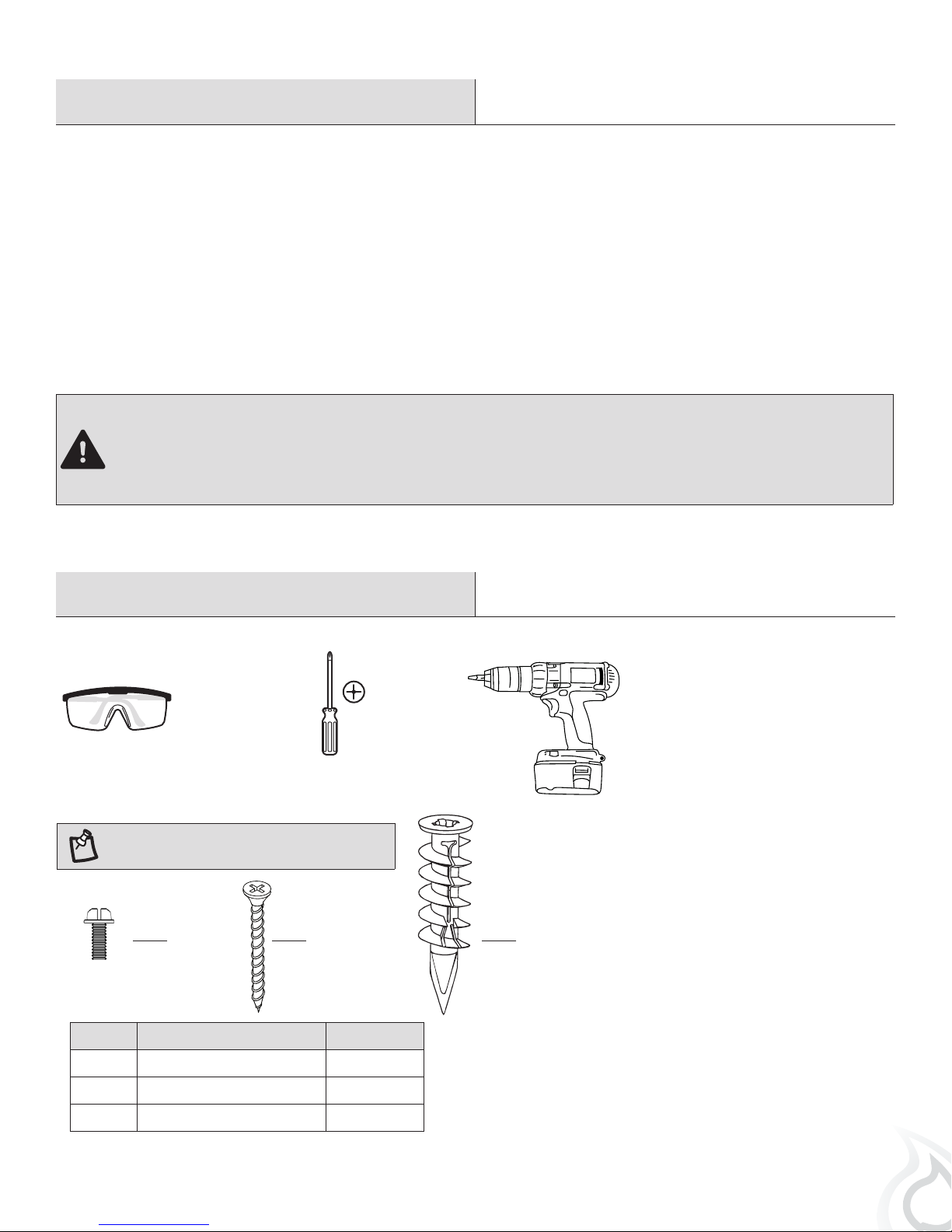
TOOLS REQUIRED (not included)
Safety goggles
HARDWARE INCLUDED
NOTE: Hardware shown to actual size.
AA
Part Description Quantity
BB CC
Phillips
screwdriver
Power drill
AA Small Screw 12
BB Large Screw 2
CC Wall Anchor 2
5
Pre-Installation (continued)
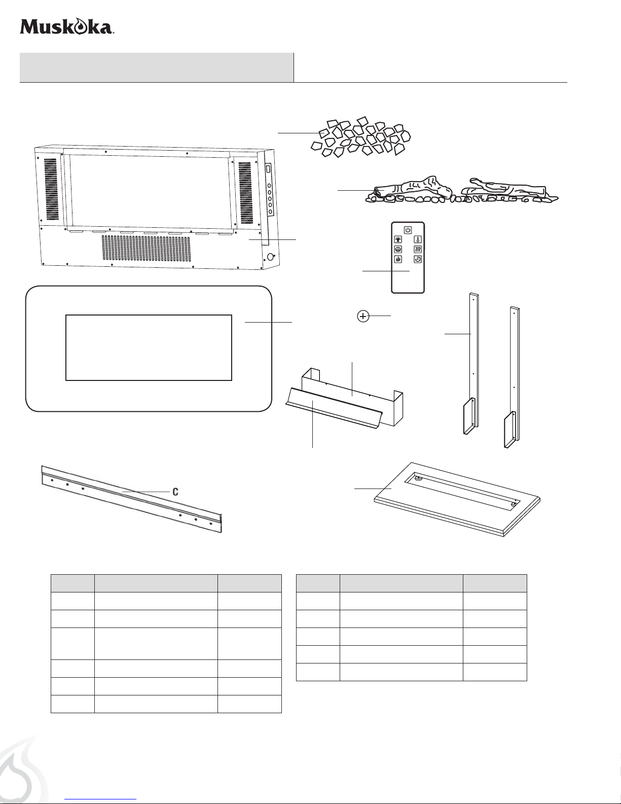
PACKAGE CONTENTS
D
F
A
K
Part Description Quantity
A Electric Firebox 1
B
I
H
J
Part Description Quantity
H Deector 1
L
G
B Glass Front 1
C Mounting Bracket (attached
to the Firebox A)
D Acrylic Crystals 1
F Log Set 1
G Table Top Support 2
Note: Both table top supports are identical.
6
I Front 1
1
J Table Top Base 1
K Remote Control 1
L Battery 1
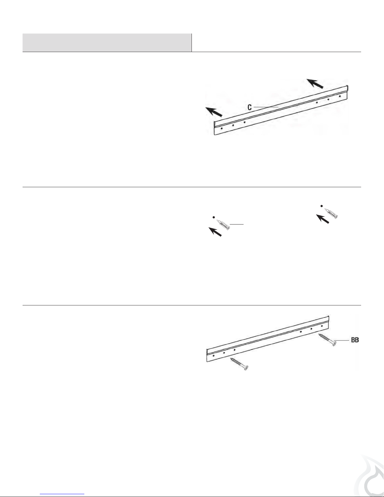
Installation - Wall-Mount
Positioning the mounting bracket
1
□ Choose a solid wall. Position the mounting bracket (C) where
the electric rebox (A) is to be installed on the wall, and
ensure that the mounting bracket (C) is level.
□ Use a pen to mark the 2 mounting holes on the wall at the
desired mounting location, using the mounting bracket (C) as
a template.
Securing the mounting bracket
2
□ Insert the 2 self-drilling wall anchors (CC) into the wall where
previously marked. If installing the mounting bracket (C) to a
wall stud, there is no need to drill the holes in the wood and
no need for the plastic wall anchors (CC). It is recommended
to install the mounting bracket to at least one stud.
Securing the mounting bracket
3
□ Secure the mounting bracket (C) to the wall using 2 large
screws (BB).
CC
7
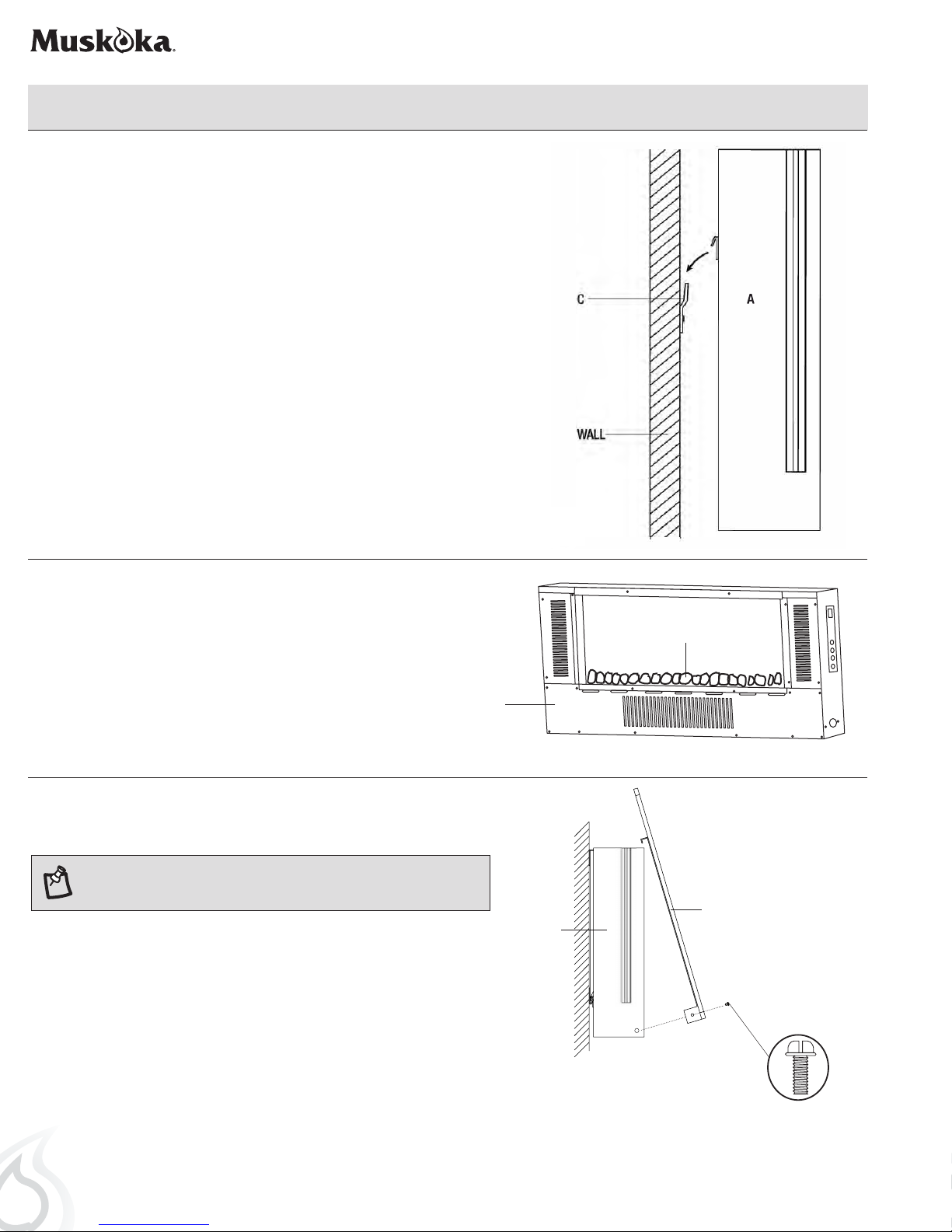
Installation - Wall-Mount (continued)
Hanging the electric rebox
4
□ Hang the electric rebox (A) on the mounting bracket (C).
Inserting the ember bed
5
□ Arrange the ember beds (acrylic crystals [D] pebbles [E] or
log set [F] ) along the inset window ledge at the front of the
electric rebox (A).
Installing the glass front
6
NOTE: This glass front is heavy. It is recommended that you use two
people at this stage to prevent damage to the glass front or the electric
rebox.
□ Lift the glass front (B) into place, making sure the 2 tabs on the top
back of the glass front (B) t securely into the holes on the top of the
electric rebox (A).
□ Secure the glass front (B) by fastening two small screws (AA) on both
sides.
D, E, or F
A
B
A
8
WALL
AA
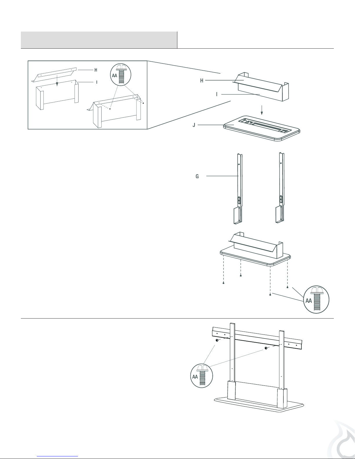
Installation - Table Top
Assembling the Table Top Stand
1
□ Attach the deector (H) to the front (I) using 2 small screws
(AA). Slide the whole part on to the table top base (J).
□ Attach the left and right table top supports (G) to the table
top base (J) using 4 screws (AA).
Securing the mounting bracket
2
□ Use a screwdriver to secure the mounting bracket (C) to the
table top stand with 2 small screws (AA).
9
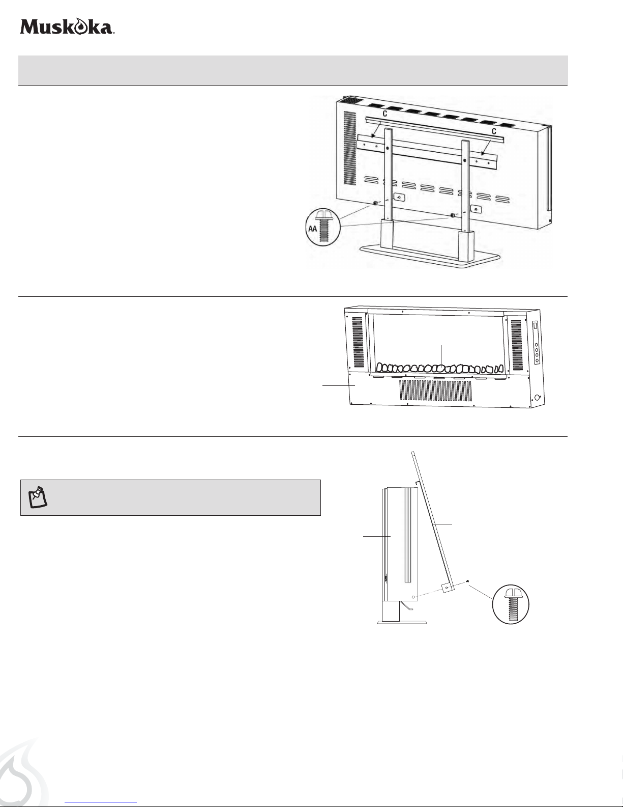
Installation - Table Top (continued)
Securing the electric rebox
3
□ Using a screwdriver, secure the electric rebox (A) to the the
mounting bracket (C) with 2 small screws (AA).
Inserting the ember bed
4
□ Arrange the ember beds (acrylic crystals [D], pebbles [E] or
log set [F] ) along the inset window ledge at the front of the
electric rebox (A).
D, E, or F
A
Installing the glass front
5
NOTE: This glass front is heavy. It is recommended that you use two
people at this stage to prevent damage to the glass front or the electric
rebox.
□ Lift the glass front (B) into place, making sure the 2 tabs on the top
back of the glass t securely into the holes on the top of the electric
rebox (A).
□ Secure the glass front (B) by fastening two small screws (AA) on both
sides.
B
A
AA
STAND
10
Operation
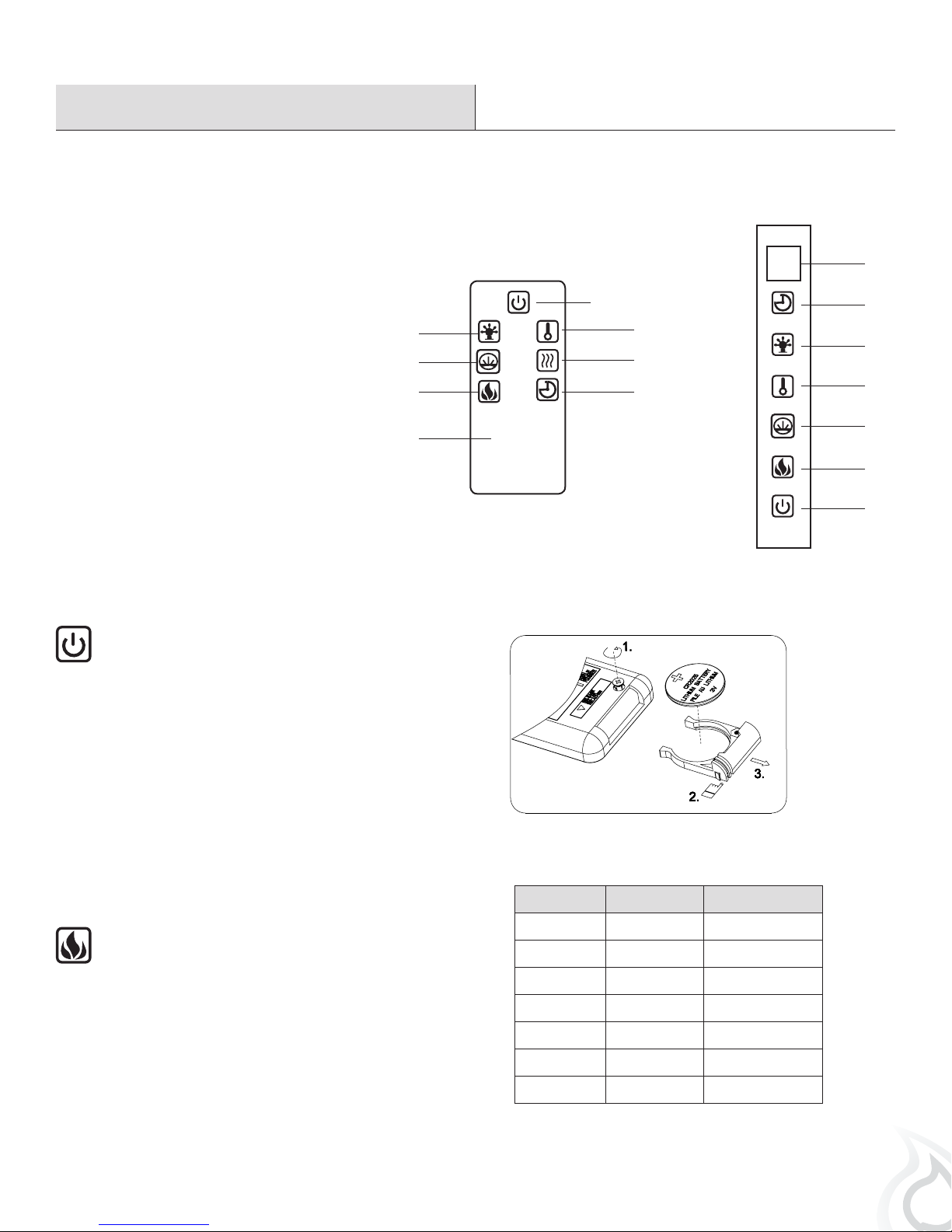
USING THE MANUAL AND REMOTE CONTROLS
On the top-right side plate of the electric replace (A) is the control panel. This panel contains the buttons to properly operate the electric
replace. The buttons on the control panel on the side of the electric replace (A) and the remote control (K) function in the same way. The
remote control has an effective range of up to 13 ft.
8
1. Power Button
2. Flame Control Button
3. Heater Control Button
4. Timer Control Button
5. Side Light Control Button
6. Heater on / off Switch
7. Ember Bed Control Button
8. Digital Display Panel
USING THE POWER BUTTON
□ The main power button (1) is located on the control panel on
the side of the electric replace.
□ Pressing the power button (1) once turns the power on.
□ Pressing the power button (1) again will turn the power off.
□ If you nd that none of the other buttons appear to work,
check to make sure that the main power (1) is turned on.
1
5
7
2
K
BATTERY REPLACEMENT
3 Volt lithium coin cell type CR 2025
3
6
4
4
5
3
7
2
1
USING THE FLAME CONTROL BUTTON
□ Press the ame control button (2) to turn on the ember
bed and ame effect.
□ Pressing the ame control button (2) once turns
ames on and lights the ember bed.
□ Pressing the ame control button (2) again will cycle
through different colors of the ember bed. The color
rotation mode will cycle through different color
settings continuously. Reference the table for more
detailed information.
This product contains a button battery. If swallowed, it could cause severe injury
or death in just 2 hours. Seek medical attention immediately.
Button Press Display Value Ember Bed Color
1st Press 1 Orange
2nd Press 2 Green
3rd Press 3 Blue
4th Press 4 Orange/Green
5th Press 5 Orange/Blue
6th Press 6
7th Press 7 Cycle
Orange/Green/Blue
11
Operation (continued)
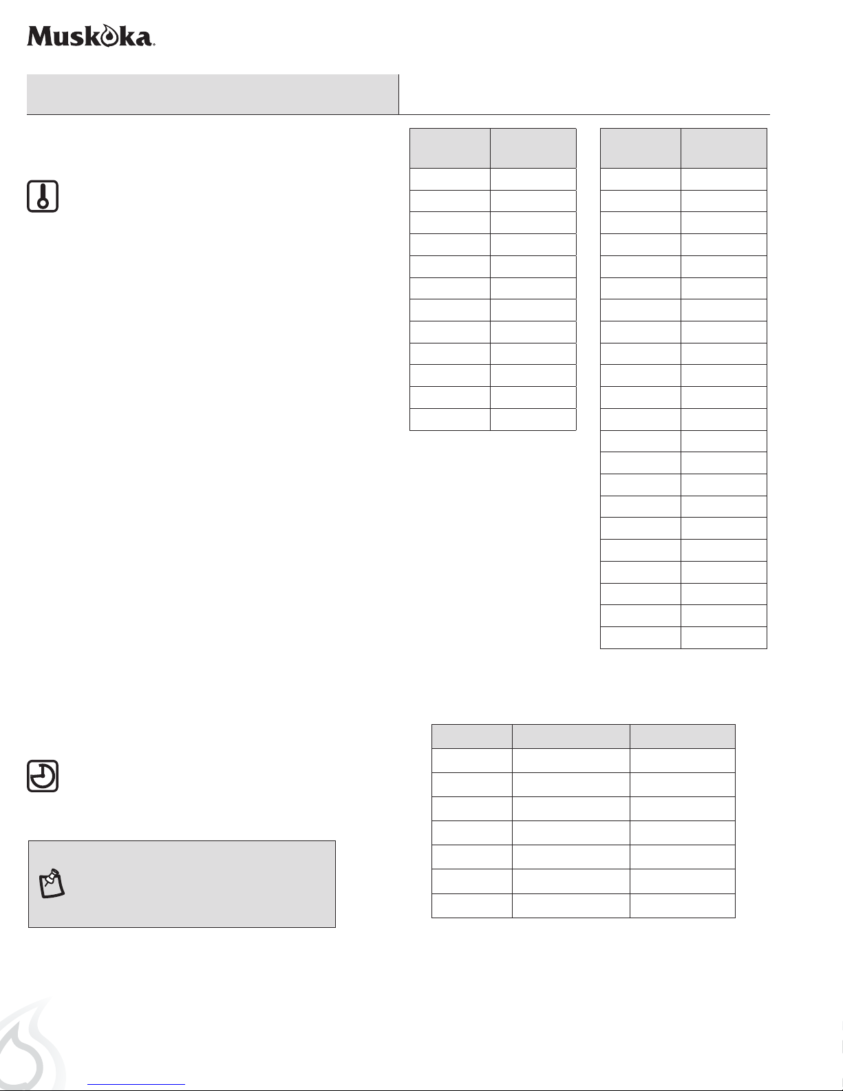
USING THE THERMOSTAT CONTROL BUTTON
□ Pressing the heat button (3) once turns the heater fan
on.
□ Press and hold the heater button for 5 seconds to
enter the temperature mode. After 5 seconds press
the heat button to cycle through the different heat
settings. Continue to press the heat button to cycle
through the different heat settings.
□ Once the desired room temperature is reached the
heater fan will deactivate.
□ Reference the table for more information.
□ To display the temperature setting in either Fahrenheit
or Celsius, press the heat button (3) of control panel
once, then press and hold the power button (1) of
control panel for 5 seconds. The display will beep and
switch between Fahrenheit or Celsius.
Button
Press
1 17°C
2 18°C
3 19°C
4 20°C
5 21°C
6 22°C
7 23°C
8 24°C
9 25°C
10 26°C
11 27°C
12 ON
Celsius
Temperature
Button
Press
1 62°F
2 63°F
3 64°F
4 65°F
5 66°F
6 67°F
7 68°F
8 69°F
9 70°F
10 71°F
11 72°F
12 73°F
13 74°F
14 75°F
15 76°F
16 77°F
17 78°F
18 79°F
19 80°F
20 81°F
21 82°F
22 ON
Fahrenheit
Temperature
USING THE TIMER CONTROL BUTTON
□ Pressing the timer control button (4) will set the timer. This
interval period is shown in the display (8) on the control
panel on the side of the electric replace. The set intervals
are as listed in the table.
NOTE: If this product experiences exceptionally
high temperature, it may automatically stop heating.
If this occurs the product should be unplugged
or isolated from the main supply for a period of 5
minutes before the power is then resupplied.
12
Button Press Timer Interval Display Value
1st Press 30 Min 30
2nd Press 1 Hour 1H
3rd Press 2 Hours 2H
4th Press 3 Hours 3H
5th Press 4 Hours 4H
6th Press 5 Hours 5H
7th Press 6 Hours 6H
Operation (continued)
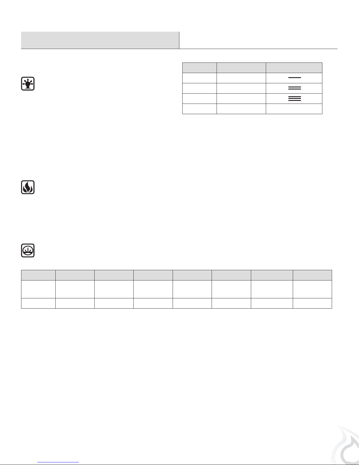
ADJUSTING THE AMBIENT SIDE LIGHTING
□ Press the side light control button (5) to turn on the
ambient lighting.
□ To change the color of the lighting press the side light
control button (5) again. You can control the side lights
color as described in the table. The color rotation mode
will cycle through different color settings continuously.
HEATER LOCKING FUNCTION
□ To turn off heat mode, press and hold the ame button for 5 seconds to enter heat lock out mode. Flame lights will ash
5 times to signal the heat function is turned off and locked out. To turn on heat mode, press and hold the heat button for 5
seconds. The ame lights will ash 5 times and the heat function will be restored. When the heat button is pressed in lock
out mode, the ember bed will ash 5 times until the heating mode is turned on.
Button Press Side Light Color Display
USING THE EMBER BED / LOGSET CONTROL BUTTON
1st Press Blue
2nd Press Red
3rd Press Cycle
4th Press Off
□ Pressing the ember bed control button (7) once will light the ember bed. Continue to press the ember bed control button (7)
to cycle through different colors of the ember bed. Reference the table for more information.
Button Press 1 2 3 4 5 6 7
Ember bed/
Logset
Display 1 2 3 4 5 6 7
Orange Green Blue Red
Red/Blue
(Mix to Purple)
Red/Green/Blue
(Mix to White)
Cycle
13
Care and Cleaning
IMPORTANT: Always unplug the power cord before cleaning the unit. Allow the unit to cool before cleaning it.
□ Wipe the exterior surface of the electric rebox occasionally with a soft, damp cloth (not dripping wet), and dry the exterior surface
before operating.
□ Do not immerse the electric replace in water.
□ Do not use any cleaning chemicals such as detergents and abrasives.
□ Do not allow the interior to get wet, as this could create a hazard.
□ Light accumulated dust may be removed from the electric replace with a soft, dry cloth.
□ To store the electric replace, put it back into its original packaging and store in a clean, dry place.
□ The blower and ame motor are pre-lubricated for a durable using time and need no further lubrication or maintenance. Dust particles
will accumulate on/in the electric replace, so periodic cleaning/vacuuming of the electric replace is recommended.
□ Always turn the heater OFF and unplug the power cord from the outlet before cleaning.
□ Cleaning of the control panel, located in the upper right-hand corner of the replace behind the sliding control panel cover, is to be
done only using a soft cloth, slightly dampened in water (if needed, a small amount of dish soap can be added to the water) and dried
using a clean, dry soft cloth. Cleaning of the screen diffuser is to be done using only water and lint free cloth. DO NOT use any abrasive
on the controls and the diffusing screen.
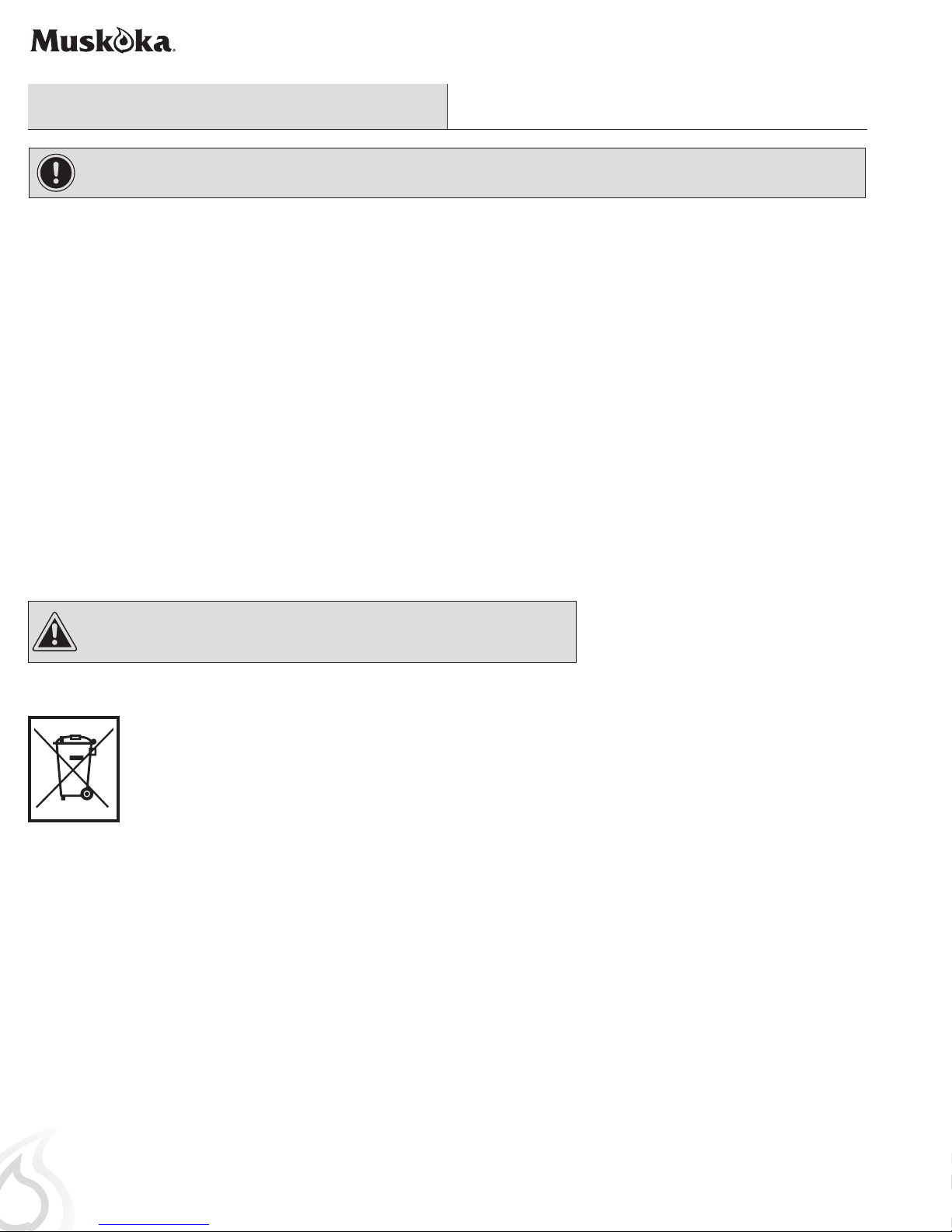
CAUTION: Do not mix old and new batteries.
Do not mix alkaline, standard (carbon-zinc), or rechargeable (ni-cad, ni-mh, etc) batteries.
DISPOSAL OF USED BATTERIES
Battery may contain hazardous substances which could endanger the environment and human health.
This symbol marked on the battery and/ or packaging indicates that used battery shall not be treated as municipal
waste. Batteries should be disposed of at an appropriate collection point for recycling. By ensuring the used batteries are
disposed of correctly, you will help prevent potential negative consequences for the environment and human health. The
recycling of materials will help to conserve natural resources. For more information about the recycling of used batteries,
please contact your local municipality waste disposal service.
14
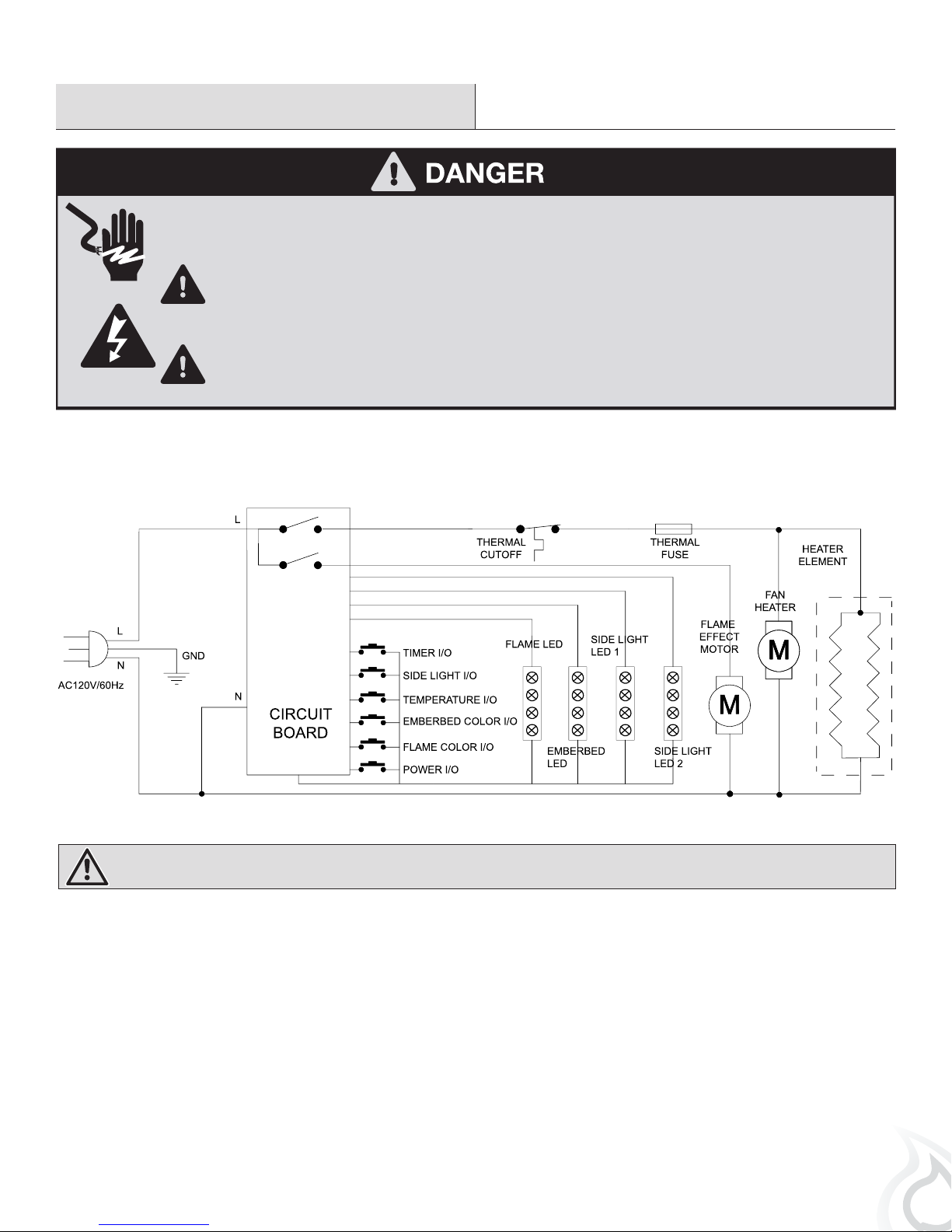
Maintenance
Disconnect power before servicing.
CIRCUIT DIAGRAM
Any electrical re-wiring of this appliance must be done by a qualied electrician. This wiring must be done in
accordance with local codes and/or in Canada with the current CSA C22.1 Canadian Electrical Code, and for US
installations, the National Electrical Code ANSI/NFPA NO 70.
If repairing or replacing any electrical component or wiring, the original wire routing, color coding and securing
locations must be followed.
WARNING: Disconnect power before servicing.
15
 Loading...