

Page 1
Page 2

Terminals marked with this symbol carry electrical current of sufficient magnitude to
constitute risk of electric shock. Use only high-quality professional speaker cables with ¼" TS or
twist-locking plugs pre-installed. All other installation or modification should be performed only
by qualified personnel.
This symbol, wherever it appears, alerts you to the presence of uninsulated dangerous
voltage inside the enclosure - voltage that may be sufficient to constitute a risk of shock
This symbol, wherever it appears, alerts you to important operating and maintenance
instructions in the accompanying literature. Please read the manual.
Caution
To reduce the risk of electric shock, do not remove the top cover (or the rear section). No user
serviceable parts inside. Refer servicing to qualified personnel.
Caution
To reduce the risk of fire or electric shock, do not expose this appliance to rain and moisture. The
apparatus shall not be exposed to dripping or splashing liquids and no objects filled with liquids,
such as vases, shall be placed on the apparatus.
Caution
These service instructions are for use by qualified service personnel only. To reduce the risk of
electric shock do not perform any servicing other than that contained in the operation instructions.
Repairs have to be performed by qualified service personnel.
1 Read these instructions.
2 Keep these instructions.
3 Heed all warnings.
Page 3

4 Follow all instructions.
5 Do not use this apparatus near water.
6 Clean only with dry cloth.
7 Do not block any ventilation openings. Install in accordance with the manufacturer’s
instructions.
8 Do not install near any heat sources such as radiators, heat registers, stoves, or other
apparatus (including amplifiers) that produce heat.
9 Do not defeat the safety purpose of the polarized or grounding-type plug. A polarized plug
has two blades with one wider than the other. A grounding-type plug has two blades and a third
grounding prong. The wide blade or the third prong are provided for your safety. If the provided
plug does not fit into your outlet, consult an electrician for replacement of the obsolete outlet.
10 Protect the power cord from being walked on or pinched particularly at plugs, convenience
receptacles, and the point where they exit from the apparatus.
11 Use only attachments/accessories specified by the manufacturer.
manufacturer, or sold with the apparatus. When a cart is used, use caution when moving the
cart/apparatus combination to avoid injury from tip-over.
13 Unplug this apparatus during lightning storms or when unused for long periods of time.
14 Refer all servicing to qualified service personnel. Servicing is required when the apparatus
has been damaged in any way, such as power supply cord or plug is damaged, liquid has been
spilled or objects have fallen into the apparatus, the apparatus has been exposed to rain or
moisture, does not operate normally, or has been dropped.
15 The apparatus shall be connected to a MAINS socket outlet with a protective earthing
connection.
16 Where the MAINS plug or an appliance coupler is used as the disconnect device, the
disconnect device shall remain readily operable.
12 Use only with the cart, stand, tripod, bracket, or table specified by the
LEGAL DISCLAIMER
TECHNICAL SPECIFICATIONS AND APPEARANCES ARE SUBJECT TO CHANGE
WITHOUT NOTICE AND ACCURACY IS NOT GUARANTEED. BEHRINGER, KLARK
TEKNIK, MIDAS, BUGERA, AND TURBOSOUND ARE PART OF THE MUSIC GROUP
(MUSIC-GROUP.COM). ALL TRADEMARKS ARE THE PROPERTY OF THEIR
RESPECTIVE OWNERS. MUSIC GROUP ACCEPTS NO LIABILITY FOR ANY LOSS
Page 4

WHICH MAY BE SUFFERED BY ANY PERSON WHO RELIES EITHER WHOLLY OR IN
PART UPON ANY DESCRIPTION, PHOTOGRAPH OR STATEMENT CONTAINED HEREIN.
COLORS AND SPECIFICATIONS MAY VARY FROM ACTUAL PRODUCT. MUSIC GROUP
PRODUCTS ARE SOLD THROUGH AUTHORIZED FULLFILLERS AND RESELLERS
ONLY. FULLFILLERS AND RESELLERS ARE NOT AGENTS OF MUSIC GROUP AND
HAVE ABSOLUTELY NO AUTHORITY TO BIND MUSIC GROUP BY ANY EXPRESS OR
IMPLIEDUNDERTAKING OR REPRESENTATION. THIS MANUALIS COPYRIGHTED. NO
PART OF THIS MANUAL MAYBE REPRODUCED OR TRANSMITTED IN ANY FORMOR
BY ANY MEANS, ELECTRONIC OR MECHANICAL,INCLUDING PHOTOCOPYING AND
RECORDING OF ANYKIND, FOR ANY PURPOSE WITHOUT THE EXPRESSWRITTEN
PERMISSION OF MUSIC GROUP IP LTD.
ALL RIGHTS RESERVED.
© 2013MUSIC Group IP Ltd.
Trident Chambers, Wickhams Cay, P.O. Box 146,Road Town, Tortola, British Virgin Islands
LIMITED WARRANTY
For the applicable warranty terms and conditions and additional information regarding MUSIC
Group’s Limited Warranty, please see complete details online at www.music-group.com/warranty
.
Page 5
EUROPORT PPA2000BT/PPA500BT
Set-up
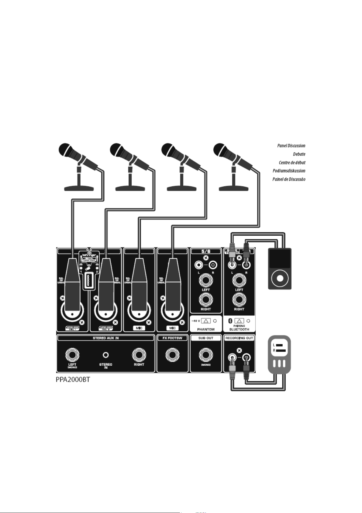
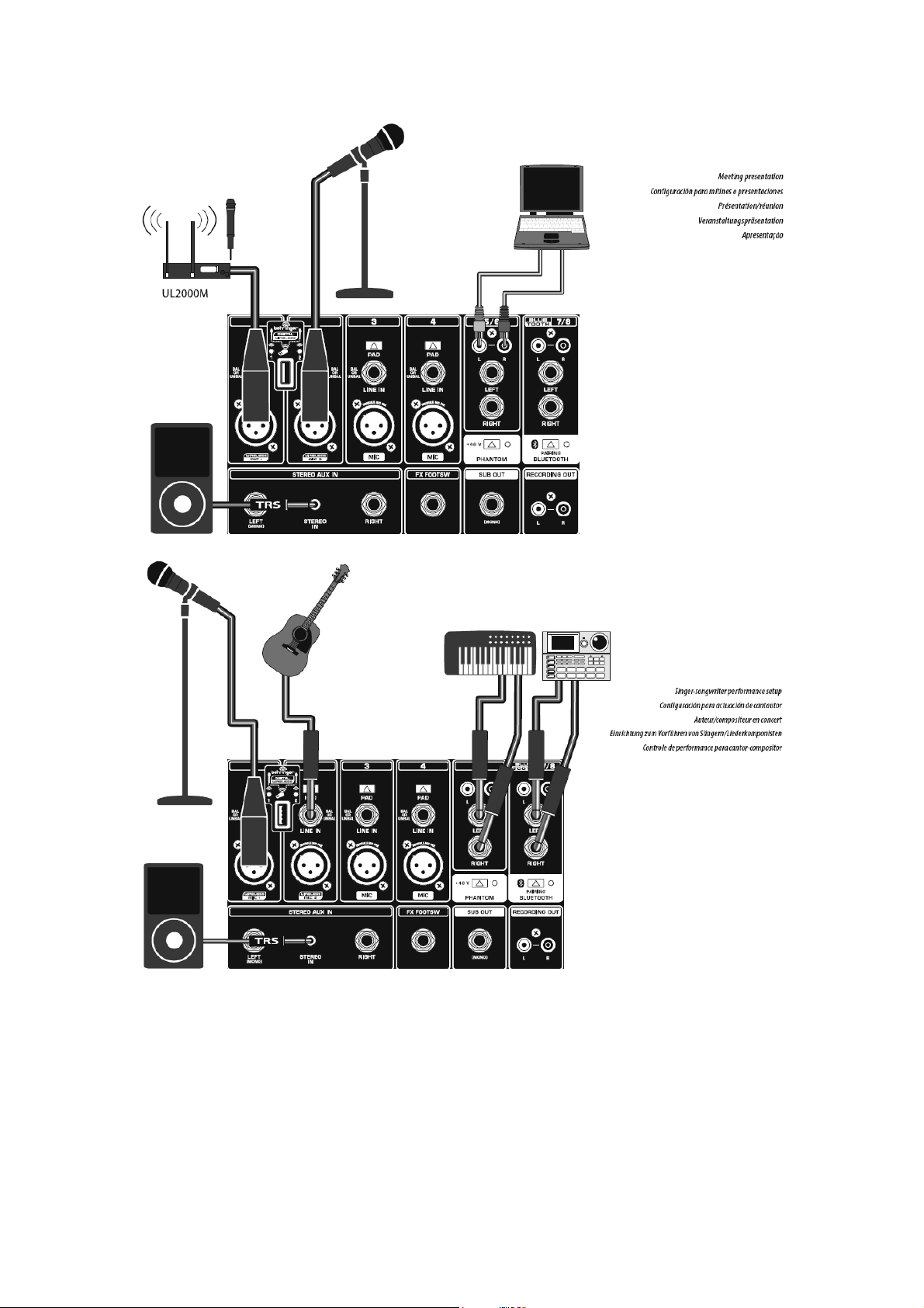
Step 1: Hook-Up
Debate Centre de débat Podiumsdiskussion
Page 6
Page 7
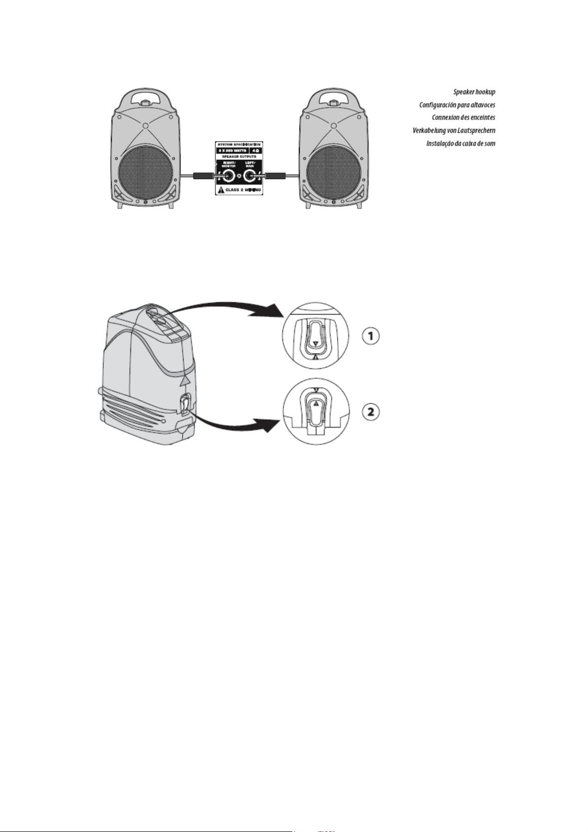
Step 2: Set-up
1,Release the top latch beneath the carrying handle
2,Release the side latches by pressing and then lifting them.
3,Remove the speakers and place them in appropriate locations.
Page 8
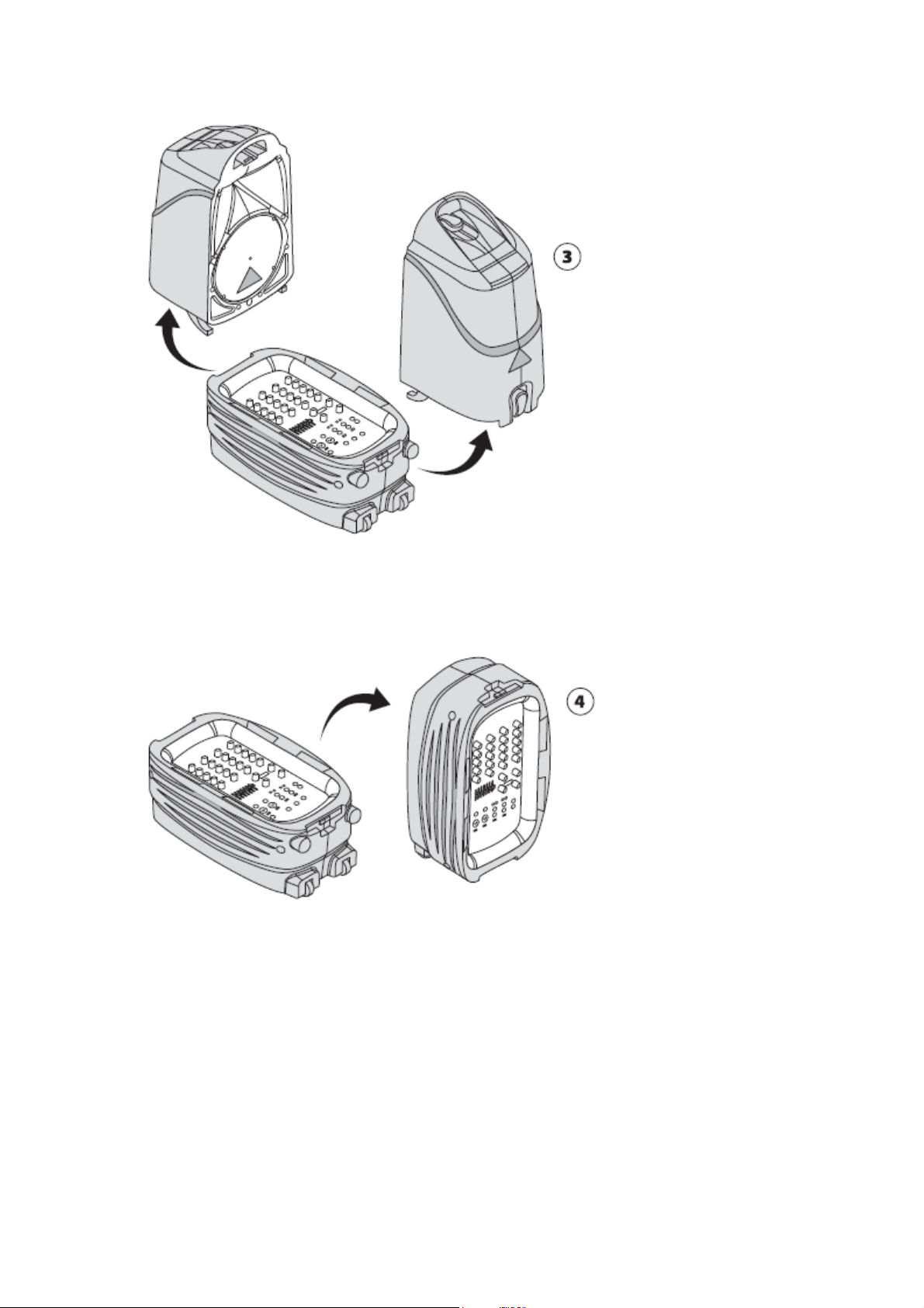
4,Stand the mixer upright.(Make sure the include speaker cables can reach both
speakers)
Page 9

Step 3: Controls.
FX knob determines how much of each
channel’s signal goes to the DIGITAL
EFFECTS PROCESSOR.
EQ KNOBS adjust the high and low
frequencies for each channel.
Page 10

PAN knob positions
each channel in the
stereo field.
PROGRAM[PUSH]
knob controls the effects
settings. Rotate this knob
to scroll through the effect
patches, and push to
select a patch.
LEVEL knob adjusts the
volume of the individual
channel in the overall mix.
MULTI-FX PROCESSOR unit
adds a selected sound effect to
any channels which have their
EFFECTS knob turned up.
Effects include reverb, chorus,
delay, and pitch shifter.
CLIP LED lights when the
input signals overloads the
channel.
FX[LEVEL] knob
controls the amount of
effects added to the
main mix.
Page 11

GRAPHIC EQ
adjusts specific
frequencies in the
sound spectrum.
LINE IN jack
connects, CD players,
sub-mixers, or other
line-level source
using cables with ¼"
plugs. These jacks
accept both
balanced and
EQ button
activates the
GRAPHIC EQ.
PAD function reduces the
channel input signal by 20dB.
Engage this button if the CLIP
LED lights up on a channel.
FBQ button
activates the FBQ
detection system.
The EQ IN button
must also be
activated for this
feature to work.
STEREO CHANNELS accept and right
sends from a single sound source using
either RCA cables or14’’ TS plugs.
MAIN LEVEL CONTROL
adjusts the overall volume of
the main mix. The MODE
switch selects stereo or mono
operation.
Page 12

DIGITAL WEIRELESS USB
input accepts the optional
BEHRINGER wireless
microphone receiver. The LEDs
indicate wireless microphone
signal input, connecting the
wireless microphone system
disables the MIC 1 and MIC 2
FX
FOOTSW
jack connects
an optional
footswitch
using a 14’’
MIC INPUT
jacks accept
dynamic(hand
held)or
condenser
microphones
using XLR
cables.
PHANTOM button
sends 48V of
phantom power to
power condenser
microphones.
SUB OUT
jack sends the
low
frequencies of
the main mono
signal to an
active
subwoofer ot
BLUETOOTH PATRING
button and indicator connect
your Bluetooth device.
AUX IN inputs
route stereo signals
directly into the main
mix through either a
sginle1/8’’TRS
stereo plug or left
and right
’’
Page 13

STEREO AUX IN
inputs route stereo
signals directly into the
main mix through either
a signal’s 1/8’’ TRS
stereo plug or left and
right 1/4’’plugs.
SPEAKER OUTPUTS connect to the
speakers using speaker cables with 1/4;;plugs.DO
NOT USE INTRUMENT CABLES AND ONLY USE
THE INCLUDED SPEAKERS.
RECORDING OUT jacks
send the main mix signal out to
an external recording device or
another mixer.
Page 14

POWER switch turns
the power to the unit
on and off
.
POWER SOURCE
accepts the included
IEC power cable into
this jack.
Step 4: Getting started
Page 15

1,Connect the included speaker cables to the speakers and to the rear SPEAKER
OUTPUTS on the mixer.
2, Make all the appropriate audio connections to the mixer. Power down all external
devices.
3, Set all the channel controls as shown (TREBLE, BASS, and BAL centered; EFFECTS
and LEVEL down/off).
4,Center the GRAPHIC EQ faders.
5, Set the MAIN LEVEL CONTROL knobs all the way down.
Page 16

6,Power up all external devices.
Power up the PPA2000BT/PPA500BT by pressing the POWER button.
7,
8,If you are using BEHRINGER wireless microphones, plug the wireless dongle into the
DIGITAL WIRELESS USB input, The DIGITAL WIRELESS LEDs will light up when the
wireless microphones become active.
9, Slowly turn the MAIN LEVEL CONTROL knobs up 1/3 of the way.
10, Adjust the relative levels of microphones
Page 17

11, If a channel’s CLIP LED lights, press the PAD button. If the PAD button is
engaged, turn the LEVEL knob down. Always use the pad button with line level inputs.
already
Adjust the left-right position of a channel in the stereo field by turning the
12,
channel’s PAN knob.
Page 18

13, Make final volume adjustments using the MAIN LEVEL CONTROL knobs.
Page 19

Step 5: Adding Effects
1,Set the FX [LEVEL] knob on the DIGITAL EFFECTS PROCESSOR to approximately a
75% setting.
Scroll through the available effects by turning the PROGRAM [PUSH] knob.
2,
The number in the display will flash.
3, Press the PROGRAM [PUSH] knob to select the effect. The number will stop flashing.
4,
While speaking, singing, or playing, turn the channel FX knob up to the desired level
on each channel to which you wish to add effects.
Page 20

5,
Adjust the FX [LEVEL] knob on the DIGITAL EFFECTS PROCESSOR up or down from
the initial 75% setting to achieve your desired overall effects level in the main mix.
Step 6: Feedback Detection
“Feedback” is the undesirable high-pitched sound created by sound waves looping
between the speakers and the microphones.
If feedback occurs, press the EQ and FBQ ON buttons.
1,
An LED will light on the EQ slider that corresponds with the specific sound frequency
2,
Page 21

feeding back.
3,
Lower the lit EQ slider until feedback stops.
Page 22

Specifications
INPUTS 1-4
4xXLR,electronically balanced Type
4x1/4’’TRS jack, electronically balanced
Approx2.2 kohm, balanced Impedance
Approx 1.1 kohm, unbalanced
Input -21 dBu @PAD/OFF
Max.gain +30dB to +10dB
Phantom power supply +48V
Signal-to-noise ratio -90dB, A-weighted
Channel separation 70dB
INPUTS 5-8
4x1/4’’TS jack, unbalanced Type
4xRCA jack, unbalanced
Impedance Approx,20ohm, unbalanced
Input sensitivity -15dBu
Max.gain +20dB
Signal-to-noise ratio -85dB,A-weighted
STEREO AUXIN
Type
Impedance 100Kohm, unbalanced
Input sensitivity -8dBu
Signal-to-noise ratio -90dB,A-weighted
TAPE OUT
Type 2x RCA , unbalanced
Impedance Approx 1Kohm
Max.output level +17dB, unbalanced
Channel separation >70 dB
SUB OUT
Type 1x1/4 mono jack, unbalanced
Impedance Approx 1Kohm
Max.output level +21dBu, unbalanced
CHANNEL EQ
1x1/4’’TS jack, unbalanced
1x stereo minijack, unbalanced
Page 23

BASS
TREBLE
EFFECTS
Converter 24-bit delta-sigma
Sampling frequency 40kHz
Display 2-digit, 7-segment
EQ
Type 7-band
LOUDSPEAKER OUTPUTS
Type 2x1/4’’ TS jack
Load impedance 8ohm
OUTPUT POWER
RMS(@8ohm) 2x160 Watts
RMS(@4ohm) 2x300 Watts
PEAK power(@8ohm) 2x500 Watts
PEAK power(@4ohm) 2x1000 Watts
SYSTEM SPECIFICATIONS
Frequency response
Distortion 0.32%@1W
POWER SUPPLY
Power consumption 2000W
Fuse T 10A H250V(100-120V~,50/60Hz)
Power input AC 100-240V,50/60Hz
DIMENSIONS/WEIGHT
Dimensions(HxWxD) Approx.26.0x13.9x34.8’’
Weight Approx.68.34 Ibs/approx.31 kg
WIRELESS SYSTEM
Connector USB
Frequency response 20Hz-15kHz,+0/-3dB
Weight Approx.68.34 Ibs/approx.31 kg
Range Max 120m
±15dB @80Hz
±15dB @12kHz
50Hz to 20kHz, ±3dB
T 5A H250V(220-240V~,50/60Hz)
Approx.660x354x883mm
Page 24

BLUETOOTH
Frequency Range 2402~2480 MHz
Channel Number 79
Version Bluetooth spec V2.1+EDR compliant
Output power 4dBm
Modulation Type GFSK ,π/4- DQPSK, 8DPSK
Date Rate 3 Mb/s
Page 25

FCC Statement
This equipment has been tested and found to comply with the limits for a Class B digital device,
pursuant to part 15 of the FCC Rules. These limits are designed to provide reasonable protection
against harmful interference in a residential installation. This equipment generates, uses and can
radiate radio frequency energy and, if not installed and used in accordance with the instructions,
may cause harmful interference to radio communications. However, there is no guarantee that
interference will not occur in a particular installation. If this equipment does cause harmful
interference to radio or television reception, which can be determined by turning the equipment off
and on, the user is encouraged to try to correct the interference by one or more of the following
measures:
—Reorient or relocate the receiving antenna.
—Increase the separation between the equipment and receiver.
—Connect the equipment into an outlet on a circuit different from that to which the receiver is
connected.
—Consult the dealer or an experienced radio/TV technician for help.
This transmitter must not be co-located or operating in conjunction with any other antenna or
transmitter.
This equipment complies with Part 15 of the FCC Rules. Operation is subject to the following two
conditions:
(1) This device may not cause harmful interference, and
(2) This device must accept any interference received, including interference that may cause
undesired operation.
Caution!
The manufacturer is not responsible for any radio or TV interference caused by unauthorized
modifications to this equipment. Such modifications could void the user authority to operate the
equipment.
 Loading...