

Page 1

April 20th 2016 www.thonk.co.uk 1
TURING MACHINE Mk ii
(APRIL 2016 ONWARDS)
Eurorack DIY Kit
Instructions
Version 1.01
Music Thing Modular Turing
Machine Mkii version
PLEASE DO NOT LINK TO OR REDISTRIBUTE THIS
DOCUMENT WITHOUT PERMISSION FROM THONK
For the most recent version of this
document please visit –
https://www.thonk.co.uk/documents/turing2016/
Refer also to the Music Thing
documentation here -
https://github.com/TomWhitwell/TuringMachine/
For all technical support please create a
Github account and log an issue here -
https://github.com/TomWhitwell/TuringMachine/issues
Chat about the build here –
https://www.muffwiggler.com/forum/viewtopic.php?t=159116
All Thonk kits are sold under our standard Terms and Conditions -
http://www.thonk.co.uk/faq/
DIY INSTRUCTIONS
This document gives detailed instructions that assume you have purchased a
complete Turing Machine kit from www.thonk.co.uk after April 2016, it also
assumes no previous knowledge of electronics.
To learn to solder try https://www.youtube.com/watch?v=IpkkfK937mU and
the Adafruit guide to excellent soldering – http://bit.ly/1l77tF4
Watch and understand that whole YouTube video! If you’re not achieving the
results shown in the video then you need to buy new tools or seek advice.
You will not end up with a working unit otherwise.
TOOLS REQUIRED
Soldering iron, snipe nose pliers, wire strippers, small flat head screwdriver
and diagonal cutters AKA snips AKA side-cutters. A Digital Multimeter is
always helpful for checking for bad solder joints and continuity. Thonk sell a
range of inexpensive tools here - http://bit.ly/1jxqF3n
Page 2
April 20th 2016 www.thonk.co.uk 2
TURING MACHINE Mk ii
(APRIL 2016 ONWARDS)
Eurorack DIY Kit
Instructions
Version 1.01
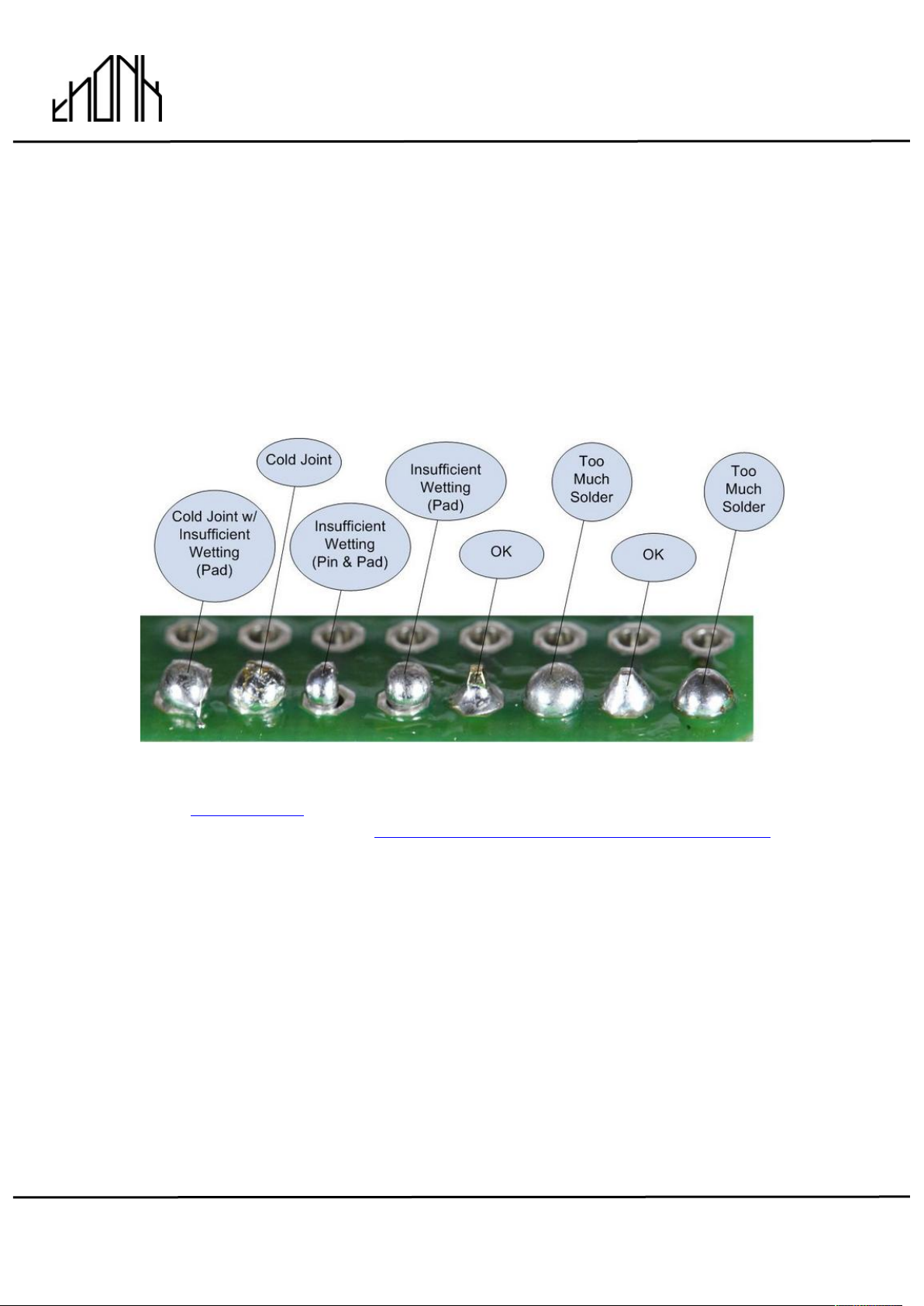
SOLDER JOINTS
Your solder joints should look like those shown as ‘OK’ below, they should
have that neat conical shape on BOTH sides of the PCB. If they don’t look
the same on both sides then stop! Work out why from the soldering guides
linked and don’t continue until you are getting those results.
This isn’t about perfectionism, you are very likely to end up with a destroyed,
damaged or defective unit if you’re not hitting that standard.
This photo is from the Adafruit guide to excellent soldering http://bit.ly/1l77tF4 and is reproduced under an Attribution-Sharealike
creative commons license - http://creativecommons.org/licenses/by-sa/3.0/
Page 3
April 20th 2016 www.thonk.co.uk 3
TURING MACHINE Mk ii
(APRIL 2016 ONWARDS)
Eurorack DIY Kit
Instructions
Version 1.01
TURING MACHINE BUILD INSTRUCTIONS
1.
To start with we advise emptying the
bags into two separate bowls or
containers so it makes it easier to
find parts.
This document has hi-res images.
ZOOM IN for a closer look
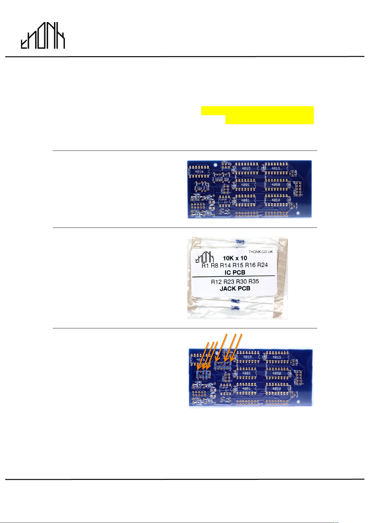
2.
Start with this PCB which we will call
the IC PCB
3.
First find the 10K resistors.
As you can see there are six
resistors listed for the IC PCB:
R1, R8, R14, R15, R16 & R24
4.
Solder the six 10K resistors into
positions R1, R8, R14, R15, R16 &
R24 as shown. You should have four
10K resistors left over for the other
PCB.
Note! Make sure your solder joints
look like the joints shown on page 2,
with solder coming through on BOTH
sides of the PCB.
If you’re not achieving this quality of
solder joint then consider changing
your iron settings or get a new
soldering iron tip, or a better solder
brand.
Page 4
April 20th 2016 www.thonk.co.uk 4
TURING MACHINE Mk ii
(APRIL 2016 ONWARDS)
Eurorack DIY Kit
Instructions
Version 1.01
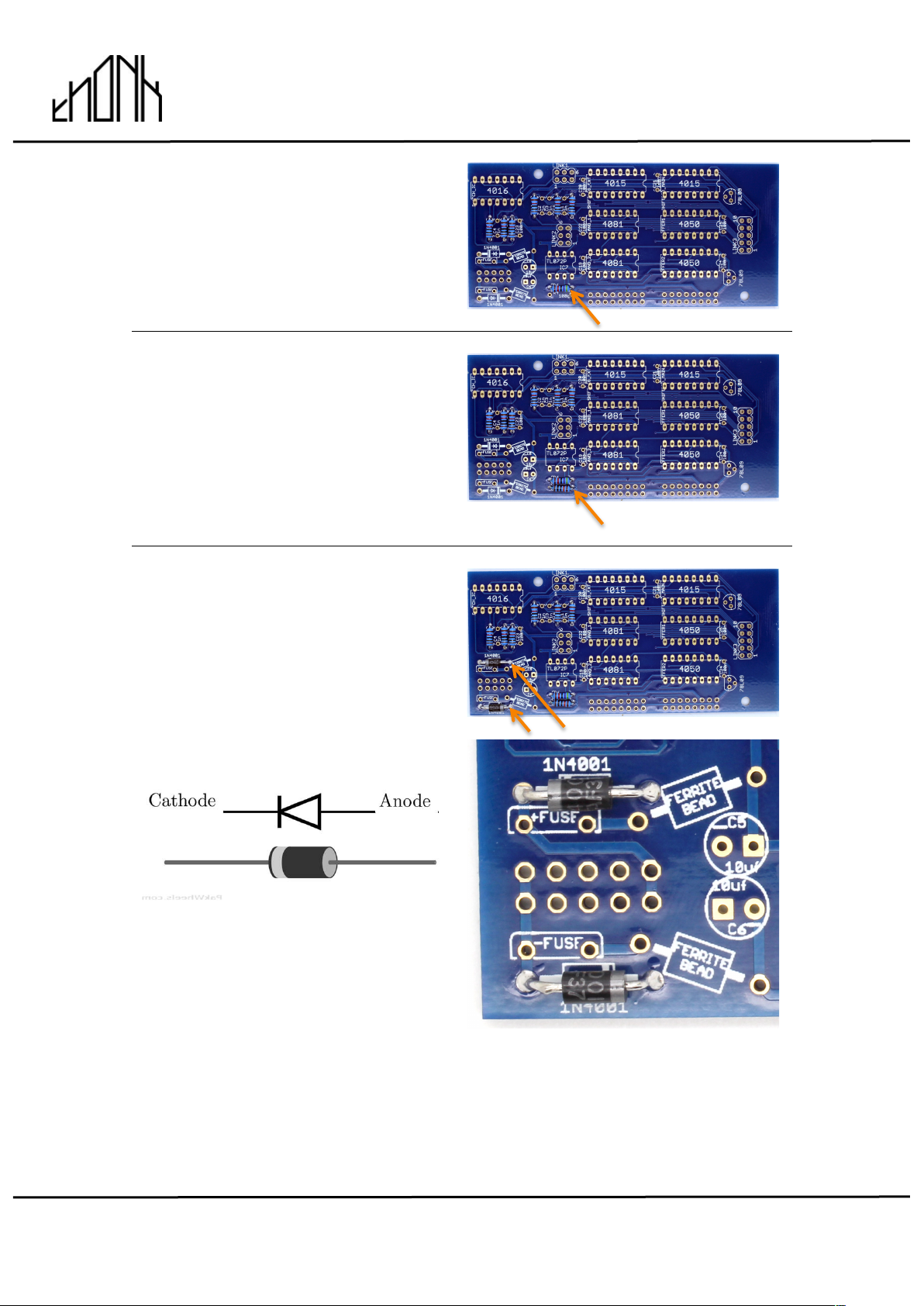
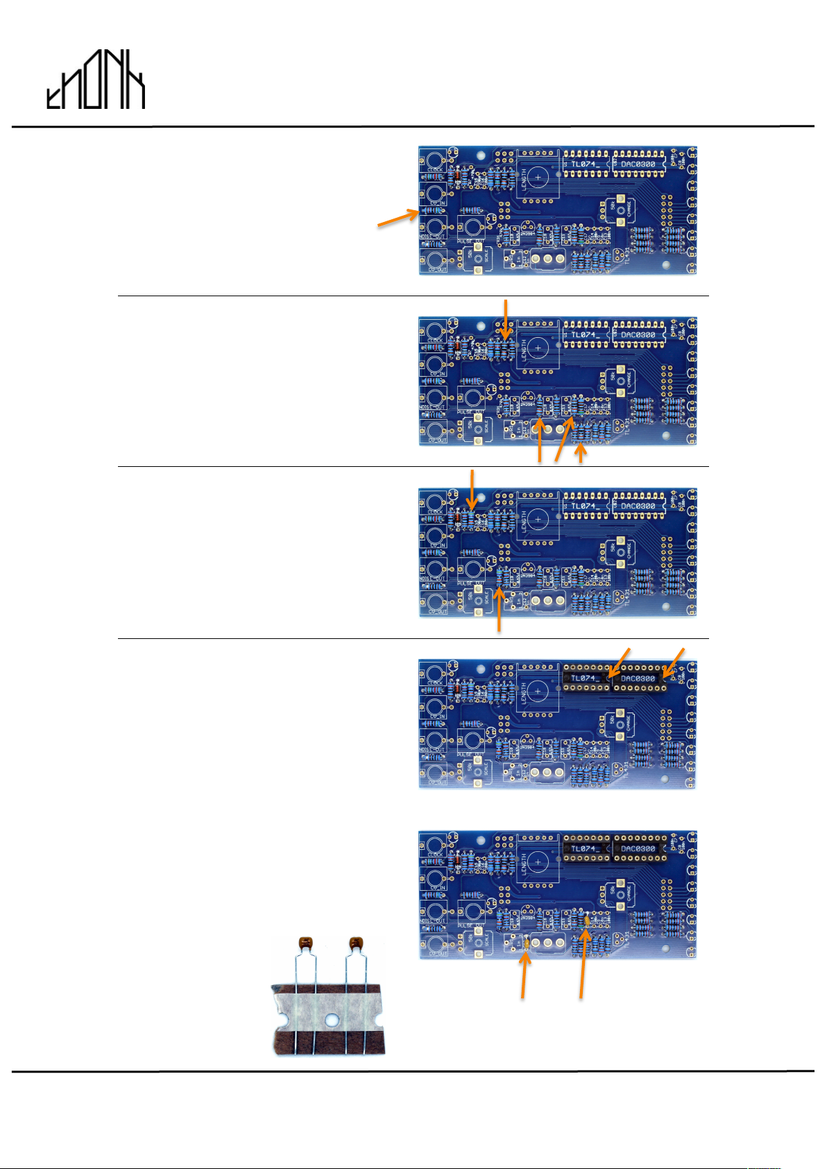
5.
Solder the single 47K resistor into
position R6 as shown
6.
Solder the single 100K resistor into
position R4 as shown
7.
Solder the two 1N4001 diodes into
the positions as shown.
NOTE! Orientation of this part is
vital, the module will not work if they
are the wrong way round.
Page 5
April 20th 2016 www.thonk.co.uk 5
TURING MACHINE Mk ii
(APRIL 2016 ONWARDS)
Eurorack DIY Kit
Instructions
Version 1.01
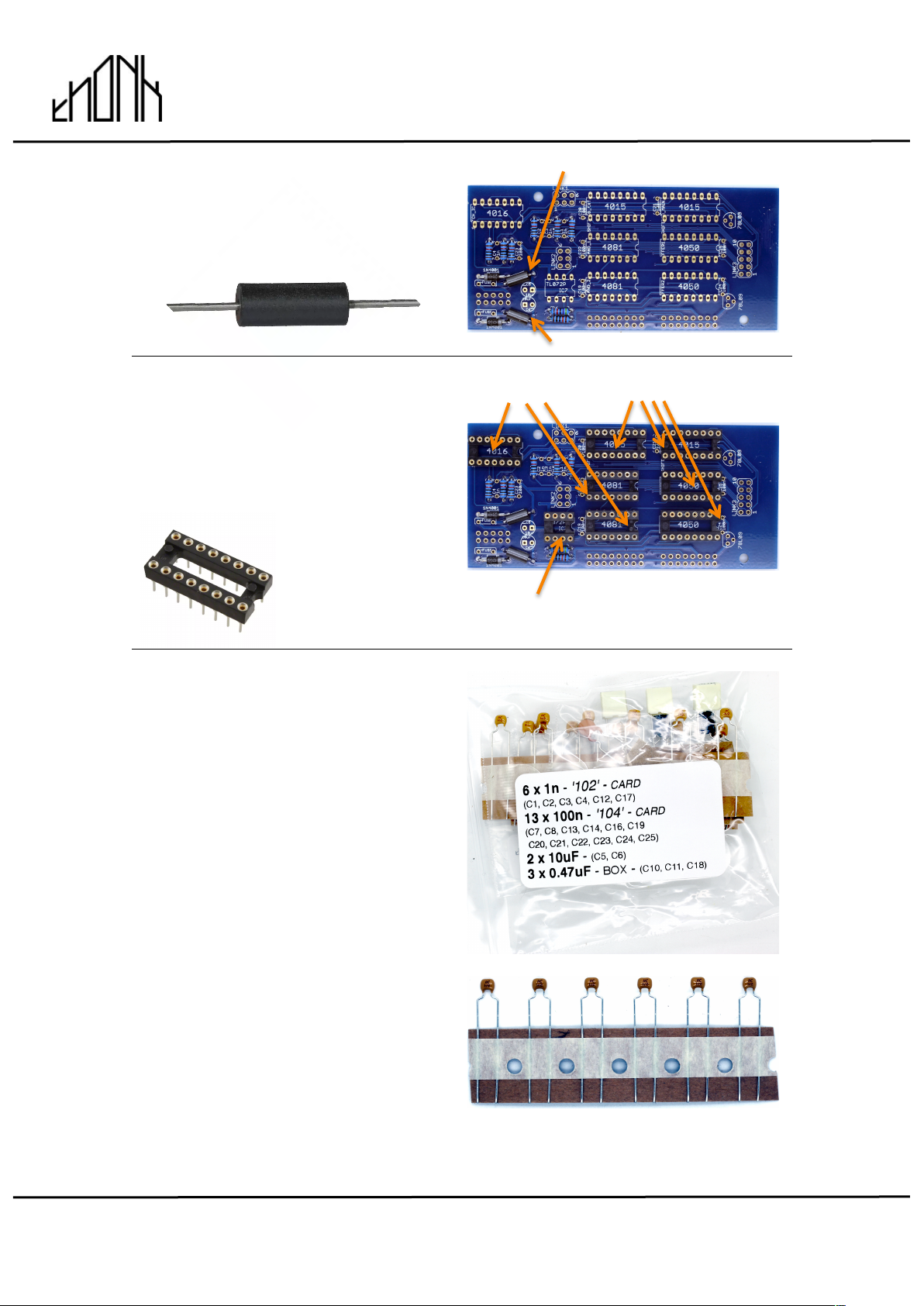
8.
Solder the two Ferrite Beads into
place as shown.
9.
Next solder the eight IC sockets
into place. Make sure the notches in
the sockets match the notches on
the silkscreen.
3 x 14 pin 4 x 16 pin
1 x 8 pin
10.
Next find the Capacitor bag and
identify the six 1n capacitors (they
are on a card strip, orange and
labeled ‘102’).
Page 6

April 20th 2016 www.thonk.co.uk 6
TURING MACHINE Mk ii
(APRIL 2016 ONWARDS)
Eurorack DIY Kit
Instructions
Version 1.01
11.
Break off four of the 1n caps and
save two for later.
Solder those four 1n caps into
positions C1, C2, C3 & C4.
12.
Next identify the twelve 100n
capacitors (they are on a card strip,
orange and labeled ‘104’).
13.
Break off seven of the 100n caps
and save five for later.
Solder those seven 100n caps into
positions C19, C20, C21, C22, C23,
C24 & C25.
Page 7

April 20th 2016 www.thonk.co.uk 7
TURING MACHINE Mk ii
(APRIL 2016 ONWARDS)
Eurorack DIY Kit
Instructions
Version 1.01
14.
Next identify the two 78L09 voltage
regulators. Make sure you check the
codes correctly! Do not mistake
them for the single TL431 or single
2N3904 included which look very
similar. With a magnifying glass you
will see 78L09 printed on the flat
face.
Solder into the positions shown.
NOTE! Ensure the flat faces on the
components match the flat faces on
the PCB silkscreen. You need to
bend the middle lead of the
component backwards to achieve
this to go through the centre hole.
Orientation is vital.
15.
Next solder the two Electrolytic 10uF
capacitors into positions C5 and C6.
NOTE! The orientation is vital, the
shorter lead on the component
should go to the circular pad marked
with a minus ‘-‘ on the PCB. Note the
component has a grey stripe on the
cylindrical body on the minus side.
Page 8

April 20th 2016 www.thonk.co.uk 8
TURING MACHINE Mk ii
(APRIL 2016 ONWARDS)
Eurorack DIY Kit
Instructions
Version 1.01
16.
Solder the three female dual row
sockets into place as shown. There
are two six pin sockets and one ten
pin sockets. Make sure the are
soldered flat against the PCB.
6 pin 10 pin
6 pin
17.
Now flip the board over and solder
the two 16 pin male headers and one
ten pin header.
10 pin 16 pin 16 pin
18.
Identify the two fuses and solder into
place as shown. The orientation
doesn’t matter, but the larger fuse
MUST go into the ‘+ Fuse’ position.
Small Large
Fuse Fuse
Page 9

April 20th 2016 www.thonk.co.uk 9
TURING MACHINE Mk ii
(APRIL 2016 ONWARDS)
Eurorack DIY Kit
Instructions
Version 1.01
19.
Next you will place the eight IC’s
required on this PCB as shown.
NOTE – Orientation is vital!
NOTE! You will need to bend the
pins on the IC inwards slightly so
they are at 90 degrees to the body of
the chip. They will come slightly
splayed out. This can be done safely
by clasping the 4 pins in a pair of
pliers (not the cutting edge near the
pivot joint though!) and very gently
bending inwards together. Repeat for
the other side.
NOTE! BOARD IS FLIPPED 180 DEG
IN THIS IMAGE
CD4050 CD4081 TL072
CD4015 CD4015 CD4016
20.
Take the two hex posts and screw
into the top of the board like shown
with two of the screws provided.
You are now finished with the back
board and are just over half-way
through the build.
NOTE! Is it late? Go to bed and do
the rest tomorrow, you have a far
better chance of building a
functioning module that way. Best
soldering advice you’ll ever get!
Page 10

April 20th 2016 www.thonk.co.uk 10
TURING MACHINE Mk ii
(APRIL 2016 ONWARDS)
Eurorack DIY Kit
Instructions
Version 1.01
21.
Let’s move onto the other PCB,
which we call the ‘Jack PCB’
22.
Identify the single 1N4148 diode and
solder into the position show. Note
the black line on the body of the
Diode should match the white line on
the silkscreen.
NOTE! Orientation of this
component is vital.
23.
Solder the three 1K resistors into
positions R18, R19 and R32 as
shown.
24.
Solder the two 1.6K resistors into
positions R27 and R28 as shown.
Page 11

April 20th 2016 www.thonk.co.uk 11
TURING MACHINE Mk ii
(APRIL 2016 ONWARDS)
Eurorack DIY Kit
Instructions
Version 1.01
25.
Solder the ten 2.2K resistors into
positions R1, R4, R6, R8, R13,
R14, R15, R16, R17 & R21 as
shown.
26.
Solder the single 3.3K resistor into
positions R20 as shown.
27.
Solder the single 5.1K resistor into
positions R26 as shown.
28.
Solder the two 15K resistors into
positions R2 and R9 as shown.
Solder the four remaining 10K
resistors into positions R12, R23,
R30 and R35 as shown.
15k 15k
10K 10K
29.
Solder the single 68K resistor into
positions R3 as shown.
Page 12
April 20th 2016 www.thonk.co.uk 12
TURING MACHINE Mk ii
(APRIL 2016 ONWARDS)
Eurorack DIY Kit
Instructions
Version 1.01
30.
Solder the single 51K resistor into
positions R5 as shown.
31.
Solder the four remaining 100K
resistors into positions R10, R11,
R22 and R29 as shown.
32.
Solder the two 470K resistors into
positions R7 and R31 as shown.
33.
Solder the two remaining IC Sockets
into the positions shown. Make sure
the notches in the sockets match the
notches on the silkscreen.
34.
Find the two remaining 1n capacitors
(marked ‘102’) and solder into
positions C12 and C17 as shown.
Page 13

April 20th 2016 www.thonk.co.uk 13
TURING MACHINE Mk ii
(APRIL 2016 ONWARDS)
Eurorack DIY Kit
Instructions
Version 1.01
35.
Next solder the single 10n capacitor
(marked ‘103’) into position C9 as
shown.
Next solder the remaining five 100n
capacitors (marked ‘104’) into
position C7, C8, C13, C14 & C16 as
shown.
You may have one 100n cap spare!
10n
100n 100n 100n
36.
Solder the single blue trimmer into
position as shown. Make sure it is
flush to the surface on the PCB.
37.
Next identify the single 2N3904
transistor. Make sure you check the
codes correctly! Do not mistake it for
the TL431
Solder into the position shown.
NOTE! Ensure the flat face on the
component matches the flat face on
the PCB silkscreen. You need to
bend the middle lead of the
component backwards to achieve
this to go through the centre hole.
Orientation is vital.
Page 14

April 20th 2016 www.thonk.co.uk 14
TURING MACHINE Mk ii
(APRIL 2016 ONWARDS)
Eurorack DIY Kit
Instructions
Version 1.01
38.
Next identify the single TL431
transistor and solder into the position
shown.
NOTE! Ensure the flat face on the
component matches the flat face on
the PCB silkscreen. You need to
bend the middle lead of the
component backwards to achieve
this to go through the centre hole.
Orientation is vital.
39.
Solder the three 0.47uF film box
caps into positions C10, C11 and
C18 as shown.
40.
Solder the single 330pF cap into
position C15 as shown.
41.
FLIP THE PCB OVER and solder the
three male double row pin headers
into position as shown.
6 pin
10 pin 6 pin
Page 15

April 20th 2016 www.thonk.co.uk 15
TURING MACHINE Mk ii
(APRIL 2016 ONWARDS)
Eurorack DIY Kit
Instructions
Version 1.01
42.
Identify the following panel parts:
ROTARY SWITCH x1 TOGGLE SWITCH x1
(LENGTH) (WRITE)
B50K Pot x1 B50K Pot x1 THONKICONN
(CHANGE) (SCALE) JACK SOCKETS x5 RED LED’s x10
43.
Position all the parts in section 42. as
shown on the PCB but DO NOT
SOLDER YET!
NOTE! The longer lead of the LED
MUST go to the pad marked with a
+ on the PCB silkscreen.
DO NOT SOLDER YET
Remove all washers and
nuts from the red switch.
Only use one nut and
discard the rest.
If your pots
have the small
anti-rotation tag
on then break
them off first.
Page 16

April 20th 2016 www.thonk.co.uk 16
TURING MACHINE Mk ii
(APRIL 2016 ONWARDS)
Eurorack DIY Kit
Instructions
Version 1.01
44.
If you want to fit the flat head LEDs
so they fit flush to the panel then
apply masking tape over the 10 LED
holes in the front panel.
45.
Now position the panel onto the
PCB, making sure that the jacks,
pots and switches are all aligned
correctly and the panel is sitting
completely parallel to the PCB and
flush to the tops of the components.
Secure into place by hand tightening
the Pot and switch nuts and a couple
of jack nuts.
46.
Before you solder you’re going to
push all ten LEDs into the holes into
the panel, so the flat heads are
sticking to the masking tape and
held nicely flush with the surface of
the panel.
Page 17

April 20th 2016 www.thonk.co.uk 17
TURING MACHINE Mk ii
(APRIL 2016 ONWARDS)
Eurorack DIY Kit
Instructions
Version 1.01
47.
Now with the panel holding
everything correctly aligned finally
solder all the pots, switches, jacks
and LEDs.
Double check all solder joints! There
are 45 to do all at once.
You are now finished soldering. Shut
off your iron!
Green Rotary switch – 7 solder
joints
Red Toggle switch – 3 solder joints
Green Pot – 5 solder joints
Blue Pot – 5 solder joints
LEDs – 10 solder joints in total
Jacks – 15 solder joints in total
48.
Next you will remove the metal panel
and fit the two remaining IC’s
required on this PCB as shown.
NOTE – Orientation is vital!
NOTE! You will need to bend the
pins on the IC inwards slightly so
they are at 90 degrees to the body of
the chip. They will come slightly
splayed out. This can be done safely
by clasping the 4 pins in a pair of
pliers (not the cutting edge near the
pivot joint though!) and very gently
bending inwards together. Repeat for
the other side.
DAC0800 TL074
Page 18

April 20th 2016 www.thonk.co.uk 18
TURING MACHINE Mk ii
(APRIL 2016 ONWARDS)
Eurorack DIY Kit
Instructions
Version 1.01
49.
Next mate the two boards together
as shown. Secure with two of the
remaining M3 screws
50.
Now finally put the metal panel onto
the top PCB and secure all the
remaining nuts and washers.
Put the two knobs on.
Page 19

April 20th 2016 www.thonk.co.uk 19
TURING MACHINE Mk ii
(APRIL 2016 ONWARDS)
Eurorack DIY Kit
Instructions
Version 1.01
51.
Attach the power cable like so with
the red stripe down, at the end of the
power connector indicated on the
PCB with ‘RED’
52.
You are now ready to power up and calibrate.
Complete your setup by following this video - https://vimeo.com/163160088
For all technical support please create a Github account and log an issue
here - https://github.com/TomWhitwell/TuringMachine/issues
Chat about the build here –
https://www.muffwiggler.com/forum/viewtopic.php?t=159116
 Loading...