

Page 1
DAKOTA MANDOLA KIT
651-439-9120
harpkit.com
Page 2
WOOD PARTS:
A - Neck
B - Fingerboard
C - Heel Block
D - Tail Block
E - Clamping Block
F - 2 Short Ribs
G - 4 Corner Blocks
H - 2 Mid-Ribs
I - Long Tail Rib
J - 2 Dowels, 1/4” X 1”
K - 2 Clamping Wedges
L - Back
M - 2 Braces for Back
N - Front (Soundboard)
O - 5 Braces for Front
P - Bridge
Q - Spacer Block (11”)
HARDWARE:
40” Fretwire
1 White Side Marker Rod, 5/64”
8 Gold Geared Tuners
w/bushings & 10 screws
Set of Mandola Strings
Tailpiece w/3 screws
White Nut Material
3 Wood Screws, 1
2 Tiny Nails
Drill Bit, 1/16” for tiny screws
Drill Bit, 5/64” for Marking Dots
Drill Bit, 7/64” for wood screws
Drill Bit, 1/4” for dowels
Medium Donut Ring
Assembly Instructions
-5/8”
DAKOTA MANDOLA KIT
Q
L
M
J
K
P
H
fig 1
A
B
E
F
C
G
Q
G
F
G
H
G
I
D
CUSTOMIZING OPTIONS
If you are an enterprising woodworker who wants to make this project special with
some sort of decorations, here are some ideas for you to think about. You may want
to order decorative materials now so you have them when you need them.
1 Medium Wood Rosette for the Soundhole, with Donut Ring
4 strips of Inlay Banding for trimming the Front and Back
N
O
We recommend assembling this kit with standard woodworker’s glue (such as Elmer’s Carpenters Glue or Titebond Wood
Glue). Don’t use Hotmelt glue, Superglue, 5-minute Epoxy, or the plain white School Glue for assembling the major wood
parts -- they are not strong enough for a high-tension instrument. There is no need to look for any special violin-maker’s adhesive. You may, however, see epoxy or superglue recommended in one or two steps for installing non-wood parts.
Every time you use wood glue on this project, it is wise to have a damp rag handy for cleaning up afterwards. It is always best
to scrub away any excess glue that squeezes out of the joints before it dries, especially on the outside of the instrument. Keep
your hands and workbench as clean as possible too. Glue smudges will show up vividly on the finished instrument.
ASSEMBLY INSTRUCTIONS
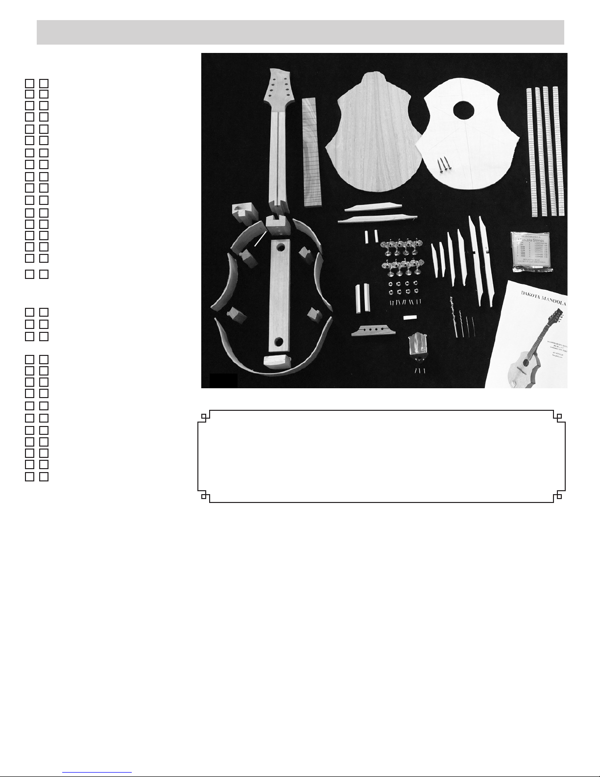
_____1. CAUTION: PLEASE DO NOT OPEN THE SEALED PLASTIC BAG CONTAINING THE FRONT
AND BACK PANELS UNTIL YOU REACH STEP #14. These two parts need to be kept very dry until you glue
the braces on them. Check over your kit parts to make sure you have everything (see fig. 1 above). Contact us right
away if you are missing parts so we can rectify the problem without causing too much delay for you. We also recommend checking off each step in the directions as you finish it. You might be skipping forward to another part of the
assembly while waiting for something to dry, and it helps to keep track of where you left off.
A NOTE ABOUT GLUE
2.
Page 3
GLUING THE BODY FRAME
Tools Required for This Stage
Masking Tape Small C -clamps Cordless Hand Drill
Plastic Grocery Bag Spring Clamps Phillips Driver Bit
Wood Glue Damp Rag 7/64” Drill Bit
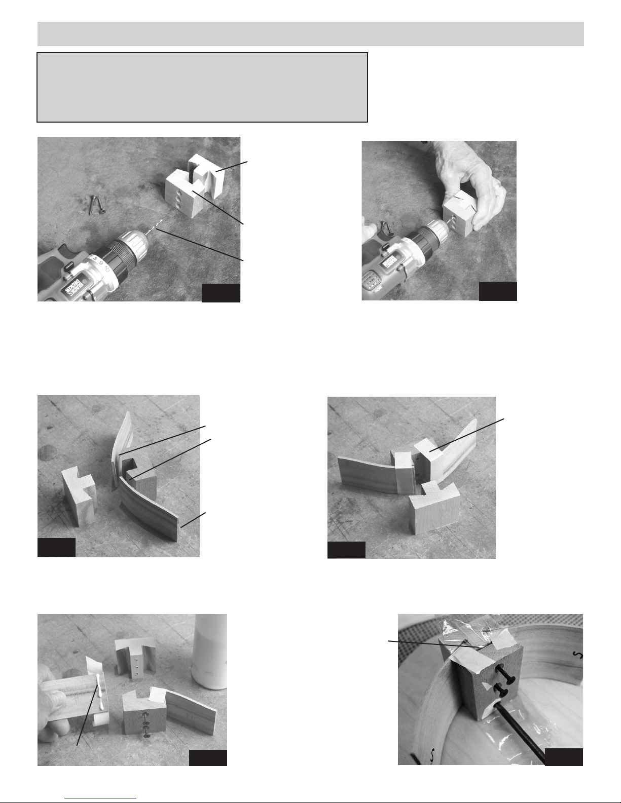
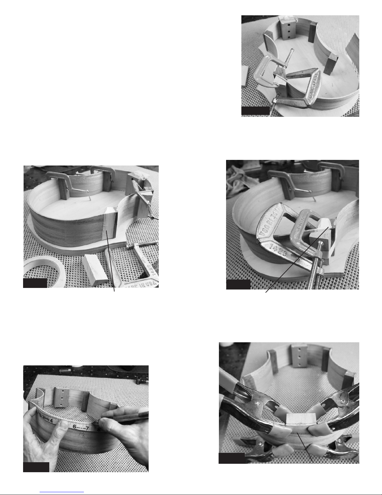
_____2. Begin at the heel where the
body will join the neck. Place the heel
block and the clamping block together
and drill two pilot holes into the clamping block using the 7/64” drill bit provided, as shown in figures 2a and 2b..
clamping block
Hold blocks
carefully on
a flat sur-
face so they
are flush
heel block
with each
other as you
7/64” drill bit
drill pilot
holes.
fig 2a
fig 2b
_____3. Find the two short ribs and look carefully for pencil markings that show “H” at one end. ese are the
ends that get glued to the heel block. Orient these pieces carefully: e end of each piece marked “H” will be
clamped against the heel block with the pencil marks facing the inside of the body (g 3a).
Tape the two short ribs to the heel block WITHOUT GLUE rst, and test the shape against the soundboard (front
piece) of the instrument. It is possible to fasten these pieces backwards and have them ared the wrong way!
short ribs
with “H”
Masking Tape
marks
fig 3a
against
heel block
“S” mark
at free end
fig 3b
Tape the short
ribs in place
WITHOUT
GLUE first.
Test the shape
to make sure it
matches the shape
of the sound-
board.
_____4. When everything checks out, put glue on the end of each short rib and tape them carefully back against heel
block as shown in fig 4a.
CAUTION: Don’t glue the
clamping block to this assembly! Put a thin plastic
barrier between the clamping block and the heel block
so you can remove the
clamping block later.
Wood Glue
fig 4a
Install the screws into the
clamping block to draw parts
firmly together until the glue
dries (fig 4b).
3.
Plastic
Bag Scrap
fig 4b
Page 4
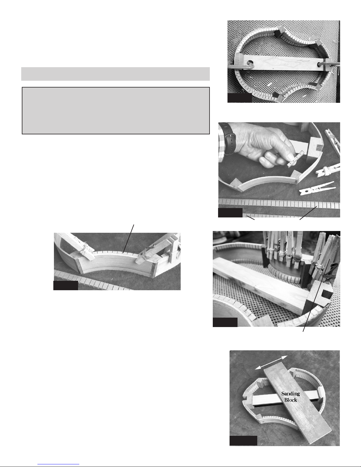
_____5. Find the 4 corner blocks. These are all the same, so they are interchangeable. Test-fit a corner to one of
the short ribs without glue to make sure your clamp will hold it firmly in place (fig 5a). We have included a couple
clamping wedges made of scrap wood in case you need them. When satisfied with the fit, glue and clamp a corner
to each short rib, making sure the rib fits all the way into the corner of the ledge (fig 5b).
Allow at least 30 minutes drying time.
After the corners are dry, you
can remove the clamps. You
can also remove the screws
holding the clamping block to
the heel block.
fig 5a fig 5b
tight fit
_____6. Now you can glue the two mid-ribs
into the corners. These ribs should flare outward, as shown (fig 6). They are symmetrical,
so it does not matter which end you glue to the
first corners. Notice the use of clamping wedges to make it easier to clamp the parts together.
fig 6
corner blockclamping wedge
_____7. Continue by gluing the next two
corner blocks at the open ends of the midribs, as shown (fig 7).
corner block
CAUTION: It’s possible to glue these parts
together crooked! Make sure all the parts are
pushed firmly into the corner blocks, that the
parts remain flush with each other, and that the
entire assembly remains flat. Lift the assembly
up and look carefully at each seam to make sure
it is tightly fit. Also make sure the whole assembly will lay on your flat work surface without rocking.
clamping wedge
fig 7
4.
Page 5
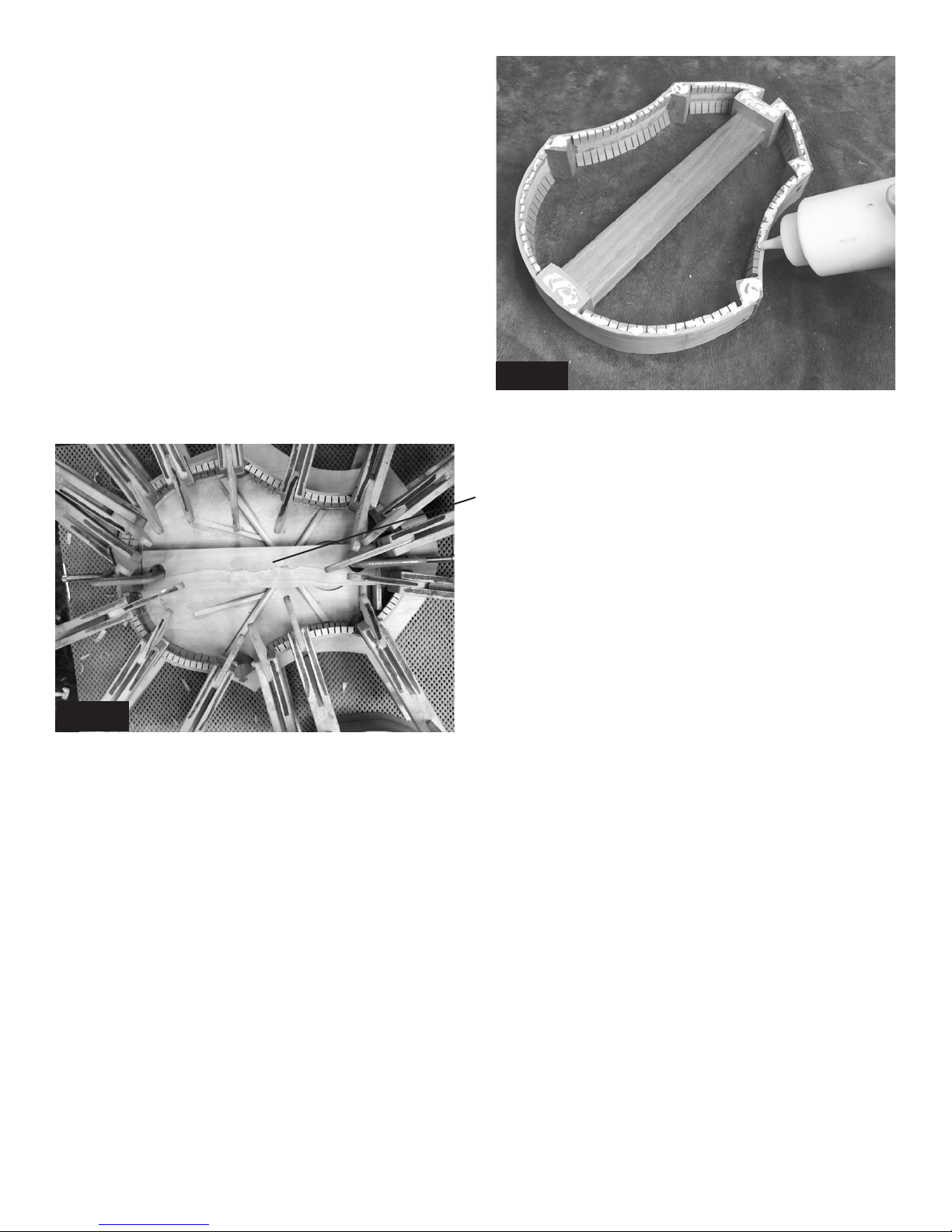
_____8. Glue just one end of the long tail rib to one corner block, as
shown (fig 8). Let the entire assembly dry overnight (or 8 hours) before
proceeding to close the frame. If you proceed too quickly, the glue is
likely to break at one or more of the corners. It takes about 8 hours for
most woodworking glue to harden completely.
While you are waiting for this assembly to dry, you can skip to step #34
(page 15) and begin shaping the neck and peghead.
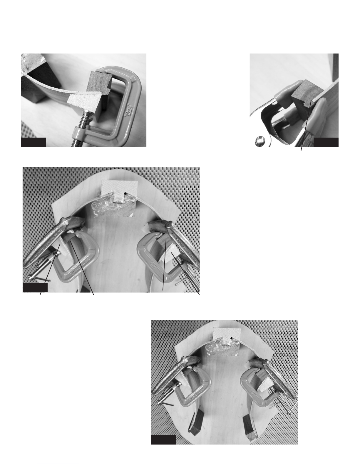
_____9. When this assembly has fully dried, you can use masking tape to
pull the final corner together roughly (fig 9a). Do this WITHOUT GLUE
first, just to make sure everything works easily for you, and no corner blocks
break free.
fig 8
Tape a clamping wedge to the joint and and then add your clamp, as shown in fig 9b, still without glue.
If the joint comes together correctly, then remove the clamp and tape so you can repeat the process with glue. Allow
this joint to dry another 8 hours (because it is under tension).
While waiting for
this last corner
to dry, go back
to shaping the
neck -- it’s good
to spend time
smoothing it to
fit your hand.
fig 9a
masking tape
fig 9b
nice tight glue joint
_____10. When dry enough to remove the last clamp, measure 7-3/8” from each end of the large curved rib and
mark it for locating the tail block (fig. 10a). Please note that this may not look exactly centered at this point because
the frame may be slightly skewed one way or the other. You’ll straighten it in the next step. Glue and clamp the tail
block in place as shown in fig 10b.
fig 10a
Center the
tail block
between
your
marks.
fig 10b
tail block
5.
Page 6
_____11. Now you need to stretch the frame a little to fit the spacer
block between the heel and tail, as shown in fig 11. DO NOT GLUE
THE SPACER! This is just a temporary piece to hold the instrument
in the proper shape until you glue the soundboard in place. You will
remove it in step #25. Use clamps to hold each end if necessary.
ADDING INNER KERFING
Spacer Block
NO GLUE!
Tools Required for This Stage
Lots of Spring Clothes Pins (or Small Spring Clamps)
Rubber Bands, i f needed
Wood Glue
Damp Rag
Sanding Block, 60-80 grit (see fig 13 below)
_____12. Add inner kerfing inside the ribs to provide a wider “shelf”
of wood for gluing the front and back panels to the frame. These
wood strips are “kerfed” to make them flexible enough to follow the
curved ribs.
Cut or break the kerfing into the approximate size needed for each
space -- it does not need to fit perfectly (fig. 12a). In fact, it is easier
if you cut it slightly shorter than the space so you can easily slide it
into position.
kerfing flush with edge of rib, or slightly higher
fig 11
fig 12a
kerfing strips
fig 12b
CAUTION: FLAT EDGE UP! Pay attention to how you orient the
kerfing strips (fig 12b). Keep the flat edge flush with the edge of
the rib, or a tad higher, and wipe off excess glue with a damp rag.
Try to keep glue off the outside of the ribs, as that will show on the
finished instrument.
Glue and clamp kerfing in place using clothes pins or small spring
clamps (fig 12c). It may be helpful to add rubber bands to your
clamps to increase clamping pressure. Allow at least 30 minutes
for drying before removing clamps.
Glue kerfing around the entire inside frame, on both front and back edges,
as shown in fig 12c.
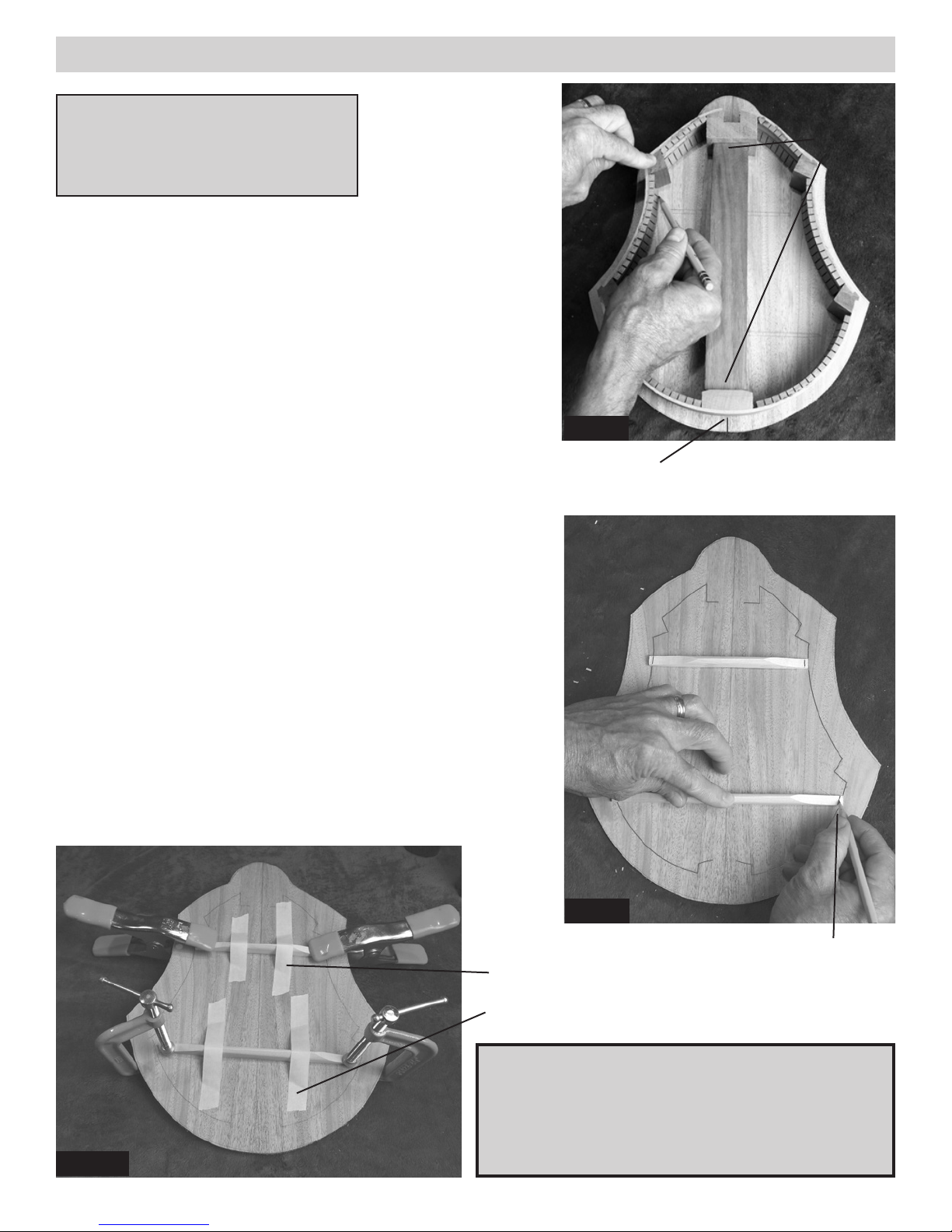
_____13. When the kerfing is dry, make yourself a long sanding block by
gluing 60 or 80 grit paper to the face of a straight scrap of wood at least
12 inches long and 3 or 4 inches wide.
This type of sanding block will rest across the frame of the body, allowing
you to sand the edges perfectly flat (fig 13). The goal is to remove glue
blobs and to sand any high spots down flush with the ribs.
fig 12c
use plenty of clamps
fig 13
6.
Page 7
PREPARING THE BACK PANEL
Tools Required for This Stage
Pencil Spring Clamps
Wood Glue Chisel or Razor Knife
Damp Rag MaskingTape
_____14. NOW YOU CAN OPEN THE SEALED BAG AND REMOVE
THE BACK PANEL (DARKER MAHOGANY PIECE). IF YOU ARE
WORKING IN A HUMID ENVIRONMENT, PLEASE STORE THE
FRONT PIECE (SOUNDBOARD) IN AN AIR-CONDITIONED (DE-
HUMIDIFIED) PLACE UNTIL YOU GET TO STEP #16.
Center the frame of the instrument on the inside face of the back panel
and outline the inside edges onto the back panel with a pencil, as shown
in fig 14a. Note the center lines at each end of this panel, and the two
horizontal lines marking the positions of the inner braces.
Once you have the outline of the instrument on the back panel, you can
position the two back braces over the lines marked and check how they
fit. If they cross your outline, mark where to trim them so they will not
interfere with the kerfing strips inside the frame (fig 14b).
NOTE: The two back braces are arched on the bottom so that when
you clamp them to the back, the back will become arched.
NO GLUE
ON
SPACER
spacer block
fig 14a
center line
Use a sharp chisel or razor knife to trim the braces to length. Note:
Some builders may prefer to cut little “pockets” (notches) in the kerfing
to receive the ends of the braces. That is the more professional method of
fitting, but it is more difficult than trimming the braces shorter.
Then you can glue the braces in place, taking care to keep them from sliding out of position under clamping pressure.
HINT: Use masking tape to hold the braces in place while you put a
clamp at each end (Fig 14c). This will produce an arched back because
of the curve in the braces. Double-check the middle to see if you might
need to add some weight in the center to achieve a firm glue joint along
the entire brace. You can prop the back on a block of wood to support
the middle, and then add weights to the center of the braces, if necessary.
Use tape to keep
braces from
slipping out
of position when
adding clamps.
fig 14b
Mark and cut
braces to length.
fig 14c
CAUTION: Don’t glue the back to the frame yet!
We glue the soundboard in place first (next page).
Store the back panel in an air-conditioned space until
you need it again near the end of the project. That’s
when you will close the box by installing the back.
7.
Page 8

PREPARING THE FRONT (SOUNDBOARD)
Tools Required for This Stage
Pencil Spring Clamps
Wood Glue Chisel or Razor Knife
Damp Rag MaskingTape
Sandpaper (60-80 grit)
Pencil
Outline
fig 16
Notice the Center Lines!
fig 17a
_____15. We highly recommend making
yourself a clamping pad for the body of the
instrument out of 3/4 plywood or particle
Clamping Pad
3/4” thick
board (fig 15). Cut it at least the size of the
soundboard, or a little larger.
fig 15
IMPORTANT NOTE ABOUT SOUNDBOARD
The front panel (soundboard) is the lighter colored piece made of solid Sitka Spruce,
and has a sound hole cut through it. If this panel has been exposed to high humidity
for more than a few hours, you will need to dry it out in an air-conditioned (dehumidified) room for a few days to shrink the grain. This will help prevent cracks
from developing in the future. Hint: Another easy way to dry it out is to place it in
the oven at low heat (200 degrees) for 6-8 hours. Put clean tin foil under it to protect it
from any grease on the rack.
_____16. The inside face has pencil marks showing the placement of the braces.
Place it on your work table with the inside facing up.
Center the frame of the instrument on the soundboard and outline the interior in
pencil (fig 16), just as you did for the back panel. Make certain the frame is centered in relation to the sound hole and the tail end. Slide the frame up toward
the top of the panel to make sure there will be room for the top brace and
the “donut” for the rosette.
_____17. (OPTIONAL)
If you purchased
a decorative rosette for the sound hole, you’ll
need to glue a “donut ring” (fig 17a) inside the
sound hole now to provide a ledge for gluing the
rosette in place. It is easiest to see the correct
position of the donut ring if you look from the
outer face of the sound board (fig 17b). Glue
this ring to the inside of the soundboard now,
before installing the braces.
fig 17b
THIS
fig 18a
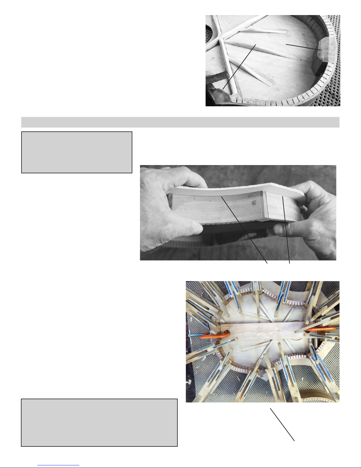
_____19. Position the X braces in place first, without glue,
and then arrange the three shorter ones as shown in fig. 19.
Trim the ends that are too long, just as you did for the back
panel.
When satisfied with the fit, glue and clamp the X braces in
place first, making sure to put glue in the joint where they
cross. Use clamps and/or weights to hold the X braces in
place firmly.
fig 19
When the X braces are dry, go ahead and glue the other
small braces too, as shown in fig 19.
NOT THIS
_____18. Find the two braces that are notched to fit
together forming an “X” (figs. 18a & 18b). These can
be joined two different ways, and we want the longer
legs to be spread as wide as they can go (fig 18a).
This will give you the maximum bracing strength on
the soundboard. Test fit the X to the soundboard, just
to be sure you have it correct.
fig 18b
fig 20a
8.
Page 9
_____20. Now you can taper the edges of the X-braces if you like,
using a chisel, coarse sandpaper or a sharp knife (fig 20a). We recommend leaving the braces full height for stability, but you can bevel the
“shoulders” to lighten them up a little. A lightweight soundboard will
sound the best.
We also like to chamfer (bevel) the inside corners of the corner blocks
and the tail block (but NOT the heel block) to give the soundboard a
little more room to vibrate (fig 20b). Basically, we like to have about
the same amount of glue surface at each corner as there is on the kerfing strips. Us a file or coarse sanding block to do this on both sides
(front and back) of the frame to achieve the best sound.
GLUING FRONT (SOUNDBOARD) TO FRAME
Tools Required for This Stage
Pencil 6 Clamps (minimum)
Wood Glue Damp Rag
Clamping Pad
_____22. Test fit the soundboard to the
frame, looking carefully around the entire
circumference to make sure the soundboard will make good tight contact with
the edges of the ribs all the way around
(fig 22).
NOTE: There is no front or back to the frame until you glue the front to
one edge, so you can choose either edge.
cham fered blocks
fig 20b
If you find a blob of glue or other irregularity or unevenness that prevents a
tight fit, go back to step 12 and use your
coarse sanding block to level off the edg-
fig 22
es of the ribs.
_____23. Continue test-fitting the frame to the soundboard WITHOUT GLUE, carefully lining it up on the
center of the soundboard. Leave the spacer block in place
for this step so the body maintains the proper length and
shape (fig 23).
Take your time here. Darken the center lines on each
part, if necessary, so you can easily see when the frame is
centered on the front panel.
Outline the outside of the frame on the soundboard
in pencil when you have it positioned where you want
it. This will help you re-position quickly when gluing.
Make sure you have enough clamps to do the gluing job
shown in step 24 -- test them to make sure they open far
enough and reach in far enough to press the frame down.
Tight fit when pressed together
DRY FIT
FRAME
TO
SOUND
BOARD
NOTE: We always clamp the frame down against the soundboard, as shown here, rather than placing the soundboard on top
of the frame. This leaves everything open and visible while you
install the clamps so you double-check for proper alignment as
you work. It also ensures that whatever excess glue squeezes out
around the edges will not run down the outside surface of the ribs
and make a big mess to clean up.
fig 23
Line up centerlines
9.
Page 10
_____24. When you are ready to proceed, squirt a good
bead of glue all the way around the frame, including the
corner blocks, heel block and tail block, as shown in figure
24a. You want enough glue so that a little excess will
squeeze out when the parts are clamped.
Then flip the frame upside down and replace it over the
soundboard within the outline you drew in step 23.
Clamp the heel and tail ends first, making sure the centerlines match up. Then put a clamp on each corner piece,
as a minimum (fig 24b). If you see areas that need more
pressure, add more clamps.
Allow 2 hours for drying before removing clamps.
fig 24a
_____25. When this assembly has dried, remove the
spacer block and save it for later (Step 41).
_____26. Trimming the excess soundboard material flush
with the ribs of the instrument requires some special care.
DO NOT attempt to cut off the overhang with a hand-held
jigsaw or a coarse hand saw. The spruce wood is fragile,
so you must work it carefully.
There are several possible tools for this delicate step, and
we’ll try to give you some guidance for whichever one
you might have available. If you don’t have any of these
fig 24b
tools, this is a great excuse to go out and buy something!
OPTION #1: HAND COPING SAW -- If you are working with just hand tools, a cheap coping saw will cut the
excess soundboard very easily. We recommend trimming a little wide, leaving 1/8” or so overhang that can easily
be sanding down flush.
OPTION #2: BAND SAW -- If you have a bandsaw available, it will do this job very quickly. But be very careful
not to cut into the frame of the instrument. A band saw could ruin the whole project in the blink of an eye!
OPTION #3: BELT SANDER -- If you have a stationary belt sander, you can sand away the excess soundboard
material quite easily. But take care to prevent sanding too deeply -- you could gouge the frame if you are not
watching closely.
OPTION #4: ROUTER (figs 26a & 26b): This is our preferred trimming tool because it is fast, safe and accurate.
Take care, however, to move the router in a clockwise direction around the soundboard (fig 26-b). This is called a
“climb cut” because the router bit is pulling the machine that same direction, “climbing” through the wood. If you
push the router against the spin of the bit, you will likely chip the soft wood and cause damage to the edges. You
don’t need a large router for this step, but you can certainly use a larger one than shown here.
10.
Page 11

Flush-trim bit
Router
fig 26a
fig 26e
Roller bearing follows ribs
fig 26b
Move router clockwise around instrument, as shown.
SANDING BLOCKS
Please note that however you trim the soundboard, you will still
need to do some careful hand sanding to finish the job. Thankfully, spruce is soft, so it sands quickly with a sanding block.
We recommend gluing sandpaper to a flat piece of wood for
sanding the outside curves and taping some sandpaper around a
curved item (like a can) for sanding the inside curves (fig 26e).
Use coarse sandpaper (60-80 grit) for removing excess wood,
and then 100-150 grit for smoothing.
Sand the remaining excess soundboard flush with the sides of the
body, as shown in figs 26f and 26g. Make sure the corner blocks
are flush and smooth with the ribs too.
fig 26f
fig 26g
Sand walnut corner blocks flush
and smooth too.
CAUTION:
ful to keep the heel
square to the top when
you are sanding (fig
26h). This will be very
important when fitting
the neck and fretboard
in place later.
Be care-
11.
Square
fig 26h
Page 12

_____ 27. Use a flat file or razor knife to finish cleaning out the notch in the heel block, as shown in figures 27a and
27b. Note how we beveled the edges of the spruce top (fig 27b). This will help make sure the neck seats fully into
the mortise slot.
beveled
edges on
spruce top
fig 27a fig 27b
OPTIONAL DECORATION: INLAY BANDING
Tools Required for This Stage
Pencil Razor Knife or Chisel Wood Glue Masking Tape
Router Inlay Bit Damp Rag Sandpaper (150 grit)
Wire Cutter
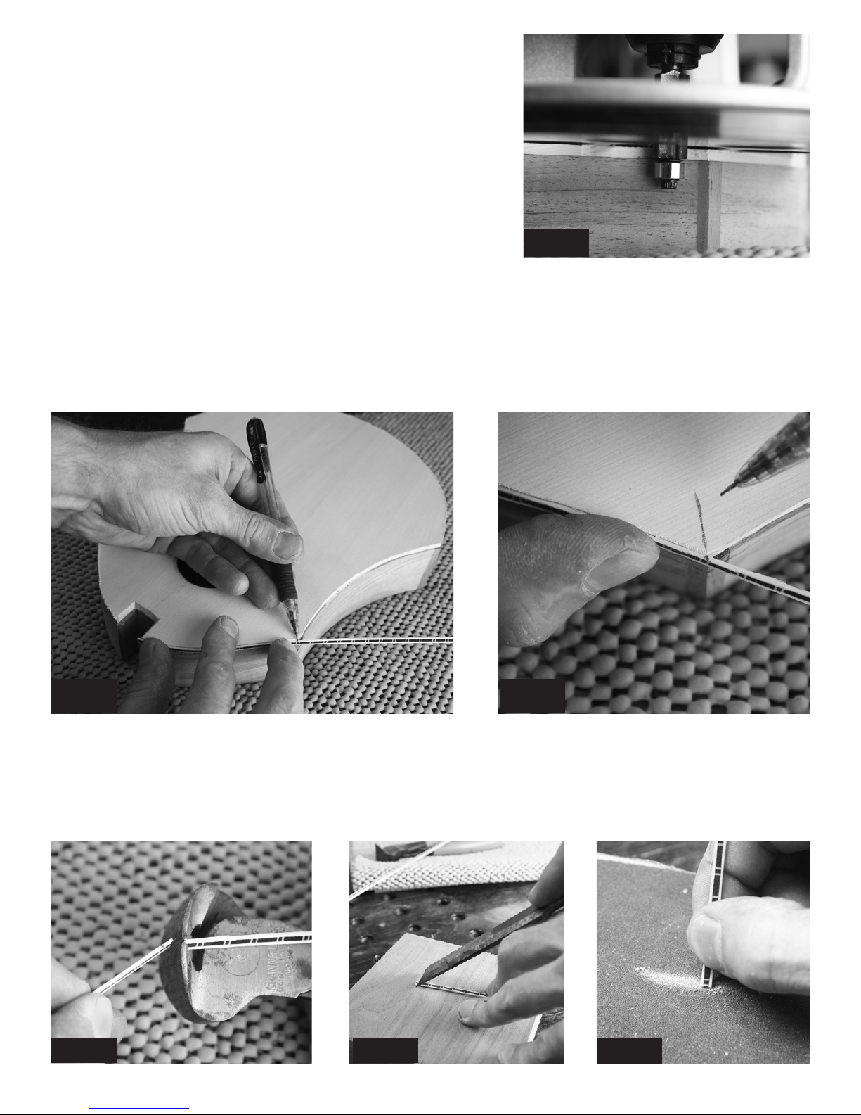
_____28. If you wish to decorate the edges of the soundboard all around the top of the
instrument, you will need a router with a small straight bit that can cut a ledge for the inlay strips. A nice inexpensive way to do this is to adapt a 1/2” flush-trim router bit with
a 3/8” diameter roller bearing, so the cutters extend 1/16” beyond the roller, as shown
in figure 28a. We have these router bits and bearings available on our website at www.
harpkit.com/inlays.
When you put this bit into your router, you only want the cutting edge to be as far above
the router base as the width of your inlay banding (fig 28b).
Be sure to test your cut on a piece of scrap wood first! The router bearing should follow
the edge of the wood, and the cutting blades should make a shallow ledge just the right
size for the inlay strip (fig 28c).
Inlay Bit
fig 28a
fig 28b
fig 28c
12.
Page 13
_____29. When satisfied with the depth of your cut, you can rout a
ledge around the circumference of instrument. Make sure to move
the router in a CLOCKWISE direction, just as you did when flush
trimming the spruce soundboard (fig 29).
If your inlay banding is more than 1/8” wide, you will be cutting
into the mahogany ribs too. That’s just fine. There’s plenty of
thickness available, and the inner kerfing strips add extra strength
to these edges also.
fig 29
_____30. Once the ledge is cleanly cut all the way around the perimeter, you can begin to install the inlay strips in
short sections that are mitered at the corner blocks, as shown in figs 30a and 30b).
Use a sharpened pencil to mark where to cut the strip, drawing the line at an angle that approximately bisects the
corner, as shown in fig 30b.
fig 30a fig 30b
_____31. Cut the strip a little beyond your mark (fig 31a), then use a razor knife or sharp chisel to make a more
precise cut on the line (fig 31b). If you need to change the angle a little or shave it a hair shorter, do that on a sanding
block, as shown in fig 31c.
fig 31a fig 31b fig 31c
13.
Page 14

_____32. When you have the first strip ready to install, squirt a thin bead of woodworker’s glue into just that short
section of the ledge where the strip will fit (fig 32a). Use masking tape to hold the strip tightly in place, as shown in
fig 32b.
HINT: Pretend the masking tape is elastic -- pull the tape both ways as you press it down against the wood.
This will pull the inlay strip all the way into the ledge.
fig 32a
fig 32b
_____33. Now you can fit the next piece of inlay in place, as shown in fig 33a. Notice the pattern of your inlay band-
ing -- your inlays will look the most professional if you trim the end of the second strip to continue the pattern of the
first strip (fig 33b). You can make this decoration appear to be seemless if you are careful and patient.
Continue around the instrument in this way, leaving
the tape in place for 8 hours before removing. Note
that the neck and fingerboard will cover the ends at
the heel block, so the strips can stop slightly short of
the mortise slot (fig 33c).
Once dry, you’ll want to remove the tape and sand
the edges clean and smooth, making sure to remove
all excess glue that squeezed out around the inlay
strips. Don’t worry about sanding the inlay strips
themselves. The colors go all the way through, so
you can clean them up and smooth the surface without removing the pattern. Just don’t sand too aggressively on the inlay strips -- they are less than
fig 33a
1/16” thick!
fig 33b
fig 33c
14.
Page 15

PREPARING THE FINGERBOARD
A NOTE ABOUT FRET MARKING DOTS
This kit comes with side markers that you will install along one edge of the fingerboard later (step 58),
but we also offer mother-of-pearl dots in our catalog (the 5 mm size is best for a mandolin). If you want to
inlay fret-marking dots on the front of the fingerboard, you should do that now, before installing the frets.
_____34. We like cutting the wide end of the fingerboard to make it more interesting, but you can leave it square.
Figure 34 shows some other options that are common for mandolin fingerboards. The simplest option is to cut a 3”
diameter arc, as shown at left, to mirror the shape of the soundhole. You can use a soup can as a pattern for that.
Make the cuts with a bandsaw and
then smooth out the edges with
sandpaper.
NOTE: Before installing frets, take
time to make sure the face of the
fretboard is nice and smooth. Sand
with progressively finer sandpaper,
starting with about 180 or 220 grit.
We go all the way to 600 grit to polish the rosewood nicely. You won’t
be applying finish to the playing surface, so this is your chance to shine
it up nicely.
fig 34
_____35. Trim your fretwire a little longer than necessary to reach across
the fingerboard (fig 35a). Then use a light hammer to tap the fret into the
slot (figs 35b & 35c).
HINT: It helps to place the fingerboard on a very solid surface, such as an
anvil or a cement floor. That way the frets will drive in more easily and uniformly. Don’t pound too hard, or you will likely distort the fretwire and/or
dent the fingerboard.
It is is important to seat the frets fully into the slots so the underside of the
fret rests on the wood. Use the curve in the wire to your advantage, tapping
the middle of the fret home after the ends are in place. That way the arch
helps prevent the ends from bending back up out of the slot.
If you over-work a fret, just remove it and use a pair of pliers to restore the
shape before making a second attempt.
fig 35a
fig 35c fig 35b
15.
Page 16

_____36. Clip the frets as close to the wood as you can (fig 36a), and then
sand the sharp metal ends down flush with the wood. Fretwire is quite soft
metal, so you can sand it or file it quite easily. We hold the fingerboard up
against a belt sander for this operation, but you can do the job by hand with
a flat file (fig 36b) or coarse sanding block (80 - 100 grit). HINT: Clothbacked sandpaper is stronger than paper-backed types for sanding metal.
fig 36b
_____37. Put a bevel on the ends of the frets by tilting your file to a 45 de-
gree angle, as shown in fig 37. Run your hand along the edges to check for
smoothness. It is important to remove all sharp metal ends and make the
edges flush and smooth.
fig 36a
fig 37
GLUING THE FINGERBOARD TO THE NECK
Tools Required for This Stage
Pencil Wood Glue Sanding Block (150 grit)
Lots of Clamps Clamping Blocks Hammer
Damp Rag Putty Knife Wire Cutter
NUT
fig 38
_____38. Once the fingerboard is done, you can
glue it to the neck (we wait on shaping the neck
until the fingerboard is attached).
The narrow end of the fingerboard should end
about 1/8” before the angle of the peghead, giving
just enough flat surface on which to place the nut
(fig 38). Hold the parts in place and draw a pencil
line on the neck to mark the end of the fingerboard.
_____39. Tap 2 tiny nails partway into the neck,
leaving most of the nail standing above the wood,
as shown in fig 39a. These will help keep the fingerboard aligned when you glue it to the neck. The
exact placement is not critical for these nails.
Then clip off most of the exposed nails, leaving
just a short stub poking above the surface of the
neck (fig 39b).
Pencil Line
fig 39a
fig 39b
16.
Page 17

_____40. Carefully align the fingerboard on the neck, checking that the narrow end matches the pencil line by the
peghead, and the sides are aligned with the neck as closely and evenly as possible. Yes, the fingerboard is standing on
those two tiny nails! Now press (or tap) the fingerboard over those two nails so the tiny nails punch a depression in
the underside of the fingerboard (fig 40a). This will enable you to re-position the fingerboard in exactly the same place
after applying glue. The nails will keep the fingerboard from slipping out of place as you apply clamping pressure.
fig 40a fig 40b
Make sure there is still room for the nut at the end of the fingerboard (fig 40b). It should stand on a little flat shelf
next to where the peghead slopes down.
_____41. Gather a bunch of clamps and scraps of wood to use as clamping blocks before doing any gluing. You
want to be well prepared for this step so you don’t end up with gaps between the neck and fingerboard. In fact, it
would be smart to experiment with your clamping system before applying any glue. You may have different types of
clamps than we use, so make sure your system will work well, and have the clamps open to approximately the right
size to save time.
Rehearse installing
plenty of clamps by
dry-fitting the fingerboard with clamping
blocks (fig 41a).
Notice how we use
long narrow scraps
of wood on each side
of the fingerboard to
make sure we can press
both edges of the fin-
fig 41a
gerboard firmly against
the neck (fig 41b).
fig 41b
_____42. When satisfied with your clamping set-up, apply glue to the neck, as shown in fig 42a. Then clamp the
fingerboard again and check for any open gaps along the sides. Wrap a damp rag around a putty knife to clean excess
glue from the each end of the fingerboard for the nut and the heel joint (fig 42b). Allow 8 hours for drying.
fig 42a fig 42b
1 7.
Page 18

SHAPING THE ASSEMBLED NECK
Tools Required for
This Stage
Curved File
Flat file
Sanding Block (150 grit)
Drum Sander (optional)
Razor Knife
fig 43a
_____43. We have done basic shaping on the neck for you, but there is some hand-
work to be done to create the profile you like and for smoothing everything out nicely.
We recommend taking your time with this step, checking how the neck feels in your
hand for playing. If you have a similar finished instrument available to look at, you
can try to copy the same shape on this kit, or you can customize this kit to fit your grip
more comfortably.
Some people with large fingers prefer to keep the fingerboard full width, but you can
trim it narrower if you like by removing equal amounts of wood from each side.
fig 43c
fig 44
fig 43b
We use a combination of tools for this process. A 3” drum
sander will remove a lot of material quickly (fig 43a), but
you’ll want to be careful to avoid creating bumps and dips
in the wood.
You can do all the shaping without power by using files (fig
43b), sanding blocks, sharp chisels, and/or razor knives (fig
43c).
Razor Knife
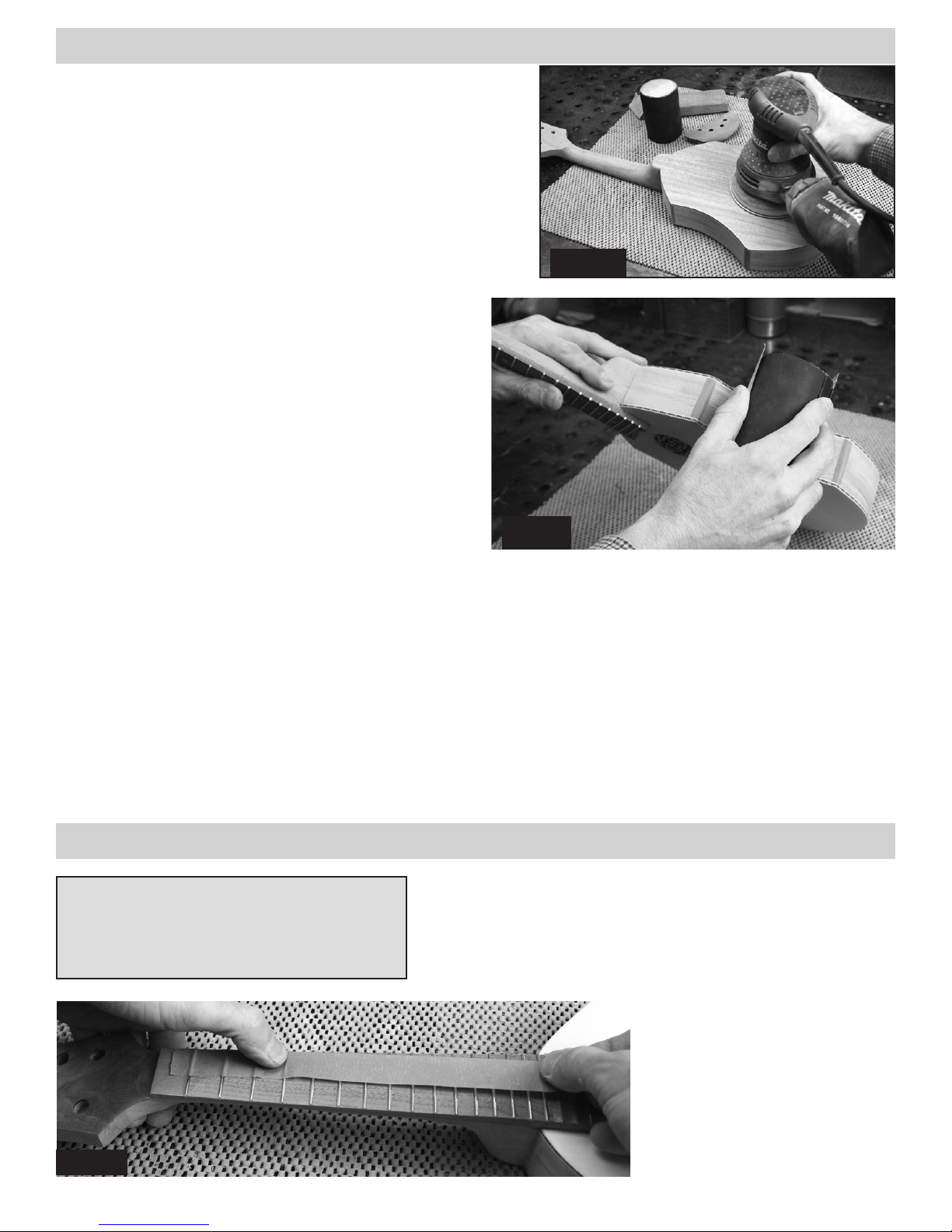
_____44. When the major shaping is done, switch to hand
sanding, with the grain, beginning with 80 grit paper and
then 150 grit to remove your tool scratches (fig 44).
POINT OF INTEREST
People sometimes ask if this instrument has an adjustable truss
rod. We build the neck with two
well-cured pieces of mahogany
for stability, and then we inlay a
carbon ber reinforcement bar
down the centerline for added
stability. We think this makes a
stronger neck than one having a
long open slot for an adjustable
truss rod.
18.
Page 19

FITTING THE NECK TO THE BODY
Tools Required for This Stage
Electric Drill 7/64” Drill Bit Masking Tape
Screw Driver Sanding Block (150 grit) Ruler
Pencil Chisel or Razor Knife Square
Wood Glue 2 Clamps Clamping Pad
_____45. Test-fit the neck to the body (fig 45). The goal is to have no visible
gaps where the neck meets the ribs, and the fingerboard should lay flat on top
of the soundboard without bending.
Take note that the back is not yet installed, so it is still possible to flex the ribs a little, if necessary, to achieve a good
fit here. So before you make drastic adjustments, we recommend installing one wood screw to hold the parts together
while you check the alignment of the neck to the body.
_____46. Use the 7/64”
drill bit to drill one pilot
hole into the neck from
inside the body (fig 46a).
We put masking tape on
the drill bit to mark the
length of the screw so we
don’t drill too deeply!
fig 45
fig 46a fig 46b
Then use a hand screw driver to install two 1-5/8” wood screws provided. NOTE: We call for a hand screw driver
here because you don’t want too much power on this screw -- you might strip out the pilot hole in the neck (fig 46b).
If you cannot draw the parts together firmly, however, use a power drill very carefully!
_____47. Now flip the instrument over and hold a straight-edge or ruler along
each side of the fingerboard so you can trace the path of those edges onto the
soundboard with a pencil (fig 47a). Compare those lines with the sound hole
and the centerline to see how straight the neck is with the body (fig 47b). The
centerline should be centered between the two outer lines.
fig 47a
fig 47b
_____48. If you need to tilt the neck one di-
rection or the other to get it aligned with the
centerline of the soundboard, mark which
side of the heel joint needs sanding. Then
remove the neck from the body and sand
the surface of that particular rib, using a flat
sanding block (fig 48a), and checking to
Square
make sure you keep the surface square with
the soundboard (fig 48b). Test fit the neck
again to see how your efforts paid off. A
little trial and error like this should bring the
neck into alignment.
fig 48a
fig 48b
19.
Page 20

Notice that the neck contacts the body more firmly on the outer edges of the
joint than in the center (fig 48c). We design the joint this way on purpose,
so it will be easier for you to achieve a nice fit on the outside.
Check carefully along the heel joint to see if there are any gaps showing on
the outside (fig 48d), and make pencil marks where you want to remove a
little wood so the entire seam closes up nicely. Then use a flat sanding block
or file to make very slight adjustments to the outer edge of the heel (fig 50c)
until you like the way the parts fit. Be careful not to overwork this. It should
only require very light sanding.
Slight
Gap
Sand the areas where the fit is
tight in order to close gaps in
other areas.
Check how the fretboard rests
on the front too.
Tight
fig 48d
Fit
Gaps
Tight
Fit
fig 48c
Sanding
Block
fig 48e
_____49. When satisfied with the fit, you can install the neck perma-
nently with wood glue. Squirt glue on all the contact surfaces: tenon,
shoulders of heel, and fingerboard (fig 49a). Install the neck using the
same screws (fig 49b).
Glue
fig 49a
fig 50a
fig 49b
Then add a couple clamps to hold the fingerboard
down fully against the soundboard (fig 49c).
Notice the scrap of wood used for preventing
the clamps from damaging the fingerboard.
Clamping Pad
Clean up
fig 49c
glue before
it hardens!
_____50. Now is a good time to “level” the tops of all the frets. Use a large flat mill file, resting on the FRETS, to
wear down any that are too high (fig 50a). Check your progress frequently to see which frets are being cut and which
ones are not. As soon as each fret has been scratched lightly with the file, you may consider them all level.
fig 50b
After leveling the tops with a file, you can do a decent job of dressing the
frets by wrapping sandpaper around your fingers, as shown in fig 50b.
Start with about 180 grit paper, sanding back and forth along the length of
the fingerboard. This will help round over the frets again, reducing the flat
areas on the frets.
Change to progressively finer sandpaper (say, 300 grit, 400 grit, and then
600 grit) to smooth and polish the frets nicely.
20.
Page 21

REINFORCING THE HEEL JOINT
fig 51a
Begin by finding the center of the seams on each
side of the tenon, and marking them with a pencil
(fig 51a).
Tools Required for This Stage
Electric Drill 1/4” Drill Bit Masking Tape
Pencil Awl Wood Glue
Chisel or Razor Knife Long Sanding Block
_____51. Once the glue is dry, remove the screw. It
is no longer needed in the joint. We’ll show you how
to reinforce the joint more permanently here.
fig 51c
Put masking tape on the 1/4” drill bit to mark the
depth of hole you want to drill for the dowels provided (fig 51c). It is best to drill a little deeper than
the length of the dowel, just to make it easy to push
the dowels in fully.
fig 51e
fig 51b
Use an awl or nail to punch-mark the center of each
seam to guide your drilling (fig 51b).
fig 51d
Drill 1/4” diameter holes for the dowels straight into
each seam to the depth of your masking tape (51d).
Make sure to get all the sawdust out of the holes.
Then squirt some glue into each hole (fig 51e).
21.
Page 22

fig 51f
fig 51g
Push a dowel fully into each hole until it is flush with
the surface of the heel (fig 51f). Use a damp rag to
clean up excess glue.
_____52. Use your long flat sanding block to
level the entire back frame of the instrument (fig
52). This will ensure a good fit when you glue
the back panel in place.
We use 80 grit sandpaper for this work. Finer
sandpaper won’t cut well enough to accomplish
the task. You need to remove any glue blobs and
high points in the kerfing that stand above the
edge of the ribs. You may also find that the heel
needs sanding down to meet the level of the ribs.
Take your time on this because any gaps between the ribs and back will show on the finished
product, unless you plan to install inlay banding
around the back.
If there is a little bit of the dowel sticking up above the
surrounding wood, use a sharp chisel or razor knife to
carve it down flush (fig 51g).
80 grit
sanding block
fig 52
Tools Required for This Stage
Wood Glue Clamps (at least 8) Clamping Pads
Router (optional) Flush Trim Bit (optional) Coping Saw or Bandsaw
Pencil or Pen Chisel or Razor Knife Sanding Blocks
_____53. We always recommend identifying the builder inside the in-
strument where you can see the inscription through the soundhole (fig
53). You could make a nice label on your computer and print it out
on parchment paper, or you can simply write your signature and date
directly on the wood with a pen. Practice on a scrap piece of the same
wood to make sure your writing will show up nicely.
INSTALLING THE BACK
fig 53
22.
Page 23

_____54. Be sure to test-fit the back without glue first, just to make sure you can pull the panel down tightly to the
ribs all the way around. Check your centerlines on these parts too! You may need to trim the ends of a brace or
something in order to align the back perfectly.
fig 54a
fig 54b
When satisfied with the fit, squirt a bead of glue all the way around the perimeter of the frame, as shown in figure 54a.
Then use lots of clamps to hold the back to the frame (fig 54b). Be sure to lift the assembly up and look carefully at
the seams so make sure the back is making full contact with the ribs all the way around the frame. Allow 8 hours’
drying time.
Coping Saw
Bandsaw
fig 55a
_____55. When the back is dry, you can trim off the ex-
fig 55b
cess overhanging material. DO NOT USE A HANDHELD POWER JIG SAW for this work. A coping saw
works fine if you don’t mind working by hand. (fig 55a).
A band saw works more quickly (fig 55b), but be
careful to avoid cutting into the frame. We like to
cut a little wide of the frame and then work the rest
down by hand, or with a router with a flush trim bit
(fig 55c).
fig 55c
Flush
Trim
Bit
HINT: You may need to use a sharp chisel or razor knife to clean up around the heel block where the
neck meets the body.
23.
Page 24

OPTIONAL DECORATIONS
_____56. (OPTIONAL) If you wish to add inlay banding around
the back, now is the time to do it. Inlay banding not only decorates
the instrument, but it also covers up gaps you might have overlooked when clamping the back to the frame. You’ll need a router
and the same inlay bit that you used for the soundboard banding.
PLEASE REFER BACK TO STEPS #28-33 for detailed instructions on installing the inlay banding. The only difference when routing the back is that you will need to stop short of the heel -- don’t
rout the ledge around the heel (fig 56). You won’t be able to bend
the inlay banding around the tight curve of the heel. Use a chisel or
razor knife to finish cutting the ledge into the corner by hand.
_____57. (OPTIONAL) If you purchased a rosette for decorating the soundhole, this is a good time to install it. If it does not fit easily into the hole, you may
need to sand the outer edge of the rosette a little until it fits.
PLEASE NOTE: If you think you might want to install a pickup inside the instrument in the future, then figure out some way to make the rosette removeable.
Tacky glue or double-stick tape might work well for temporary installation.
Put glue on the exposed ledge of the donut ring, NOT ON THE SOUNDBOARD
or the rosette. This will help you keep from making a mess. Take care to orient
the rosette pattern so it looks straight on the instrument (fig 57).
fig 56
Stop inlay
at heel
Heel
fig 57
_____58. (OPTIONAL) This kit includes a short white plastic rod that can be inlaid along one edge of the finger-
board for marking certain fret positions to guide your playing. This is a good time install those markers.
These marks should be placed on the edge that faces you as you hold the instrument. Right-handed players will put
them along the left edge, as shown in figure 58a. If you expect to play in a left-handed orientation, then just flip the
instrument over and count the spaces from the narrow end of the fingerboard (near the peghead).
fig 58a
We recommend marking at least 4 spaces (#5, 7, 10 & 12),
but you can go further up the scale as shown in fig 58. Notice that we put two dots on the 12th space, as that marks the
octave position.
Punch-mark each position first, and then drill carefully with a
5/64” drill bit to a depth of about 1/8” (Fig 58b).
fig 58b
Then you can push the white plastic rod into the hole, clip of
the excess, and move on to the next hole. Use a razor knife to
trim the plastic flush with the surrounding wood. No need for
glue on these markers.
24.
Page 25
FINAL SANDING
_____59. There may be some large areas of the instrument,
such as the soundboard and back, that need a quick sanding
with a power tool. We use an orbital hand sander with 220-grit
sandpaper for a once-over lightly to take care of major scratches and bumps (fig 59a). BEWARE: These power sanders can
dig major divots in this soft wood if you are not careful. We
just use them very sparingly on a project like this....
Now it is time to go over the entire instrument BY HAND
WITH SANDPAPER to clean up all glue spots, machine
marks, and other signs of amateur construction. Take your
time with this. It helps to have good lighting so you can
look carefully for rough spots and glue smudges.
Hand-sanding is often the least favorite part of a woodworking project, so plan a way to make it relaxing and enjoyable. Sit in a comfortable chair by the fireplace with an
old towel over your lap to catch the dust. A glass of beer
or wine, and some good music will help too.
fig 59a
DO THIS HANDWORK WITH GOOD LIGHTING!
Begin with 150-180 grit sandpaper, looking for glue blobs,
fingerprints, scratches, and machine marks. If you start with sandpaper that is too fine, you’ll work and work without
making any progress.
Sand with the grain direction whenever possible. This will give smoother results. The goal is to remove the offensive
marks with medium paper, and then switch to finer grit for making everything nice and smooth.
One more thing: A good woodworker knows that a slightly rounded corner always looks and feels better than a very
sharp corner. Yes, you can even round the edges of the inlay banding a little bit. It just takes a little sanding at an angle
with fine (220-320 grit) sandpaper to make a big difference in how it feels in your hands. NOTE: We don’t find it
necessary to use finer sandpaper than 320 until we are sanding between coats of finish.
OK, that’s our little pep talk. Now sit down and do some quality handwork. You’ll be glad you did.
fig 59b
APPLYING THE FINISH
Tools Required for This Stage
Masking Tape Razor Knife
Finish of Your Choice Applicator (brush or rag)
Mineral Spirits Paper Towels or Rags
_____60. Before applying finish to the instrument, it is best to
cover the playing surface of the fingerboard with masking tape.
Rosewood fretboards are usually not finished, except along the
edges where you might like seeing the same sheen as you put on
the neck. This wood has natural resins for protection from moisture, so additional finish is not necessary and sometimes causes
problems by becoming sticky under your fingers as you play.
fig 60a
Apply the tape carefully to cover
the entire top of the fingerboard,
frets and all (fig 60a). Use a razor knife to trim off any tape that
hangs over the edges or ends of the
fretboard.
25.
Page 26
Use a clean cloth to wipe off any sanding dust from the wood (fig 60b).
Some people buy tack cloth for this purpose, but we just use a clean rag.
Another option is to wet the rag with denatured alcohol (from the hardware store) for cleaning the wood more fully. Alcohol does not raise the
grain like water does, and it evaporates quickly, leaving no spots. But this
trick is not a necessary step -- just kind of fun to do. The alcohol will give
you a preview of the beautiful depth and color of the wood.
Now you are ready to apply the nish. Here are some recommendations:
STAIN -- STAINS are coloring agents and should only be used if you dislike the natural color of the wood. We generally discourage people from
trying to stain this project because the natural wood grain is so beautiful
with a simple clear nish. It is dicult to mask o the soundboard, for instance, and just stain the sides and back
of the body because the stain tends to “bleed” under the masking tape. If you are a novice at nishing, or facing a
deadline for completion, we especially recommend avoiding stain.
OIL -- An oil nish (such as Watco Danish Oil) will give your wood a low luster appearance, bringing out the
natural color of the grain, but it tends soak into the wood and appear dry and “thirsty” aer awhile. e principal
advantage of an oil nish is that it can be applied and wiped dry immediately, allowing you to proceed to installing
hardware (and strings) right away. e disadvantage of oil is that it usually does not give much surface protection
or sheen, unless you know how to polish out many coats of gun stock oil.
POLY URETHANE -- Any polyurethane will work ne on this project, but we like the solvent-based ones better
than water-borne versions. Our all-time favorite is wipe-on Gel Topcoat polyurethane that comes with our Instrument Finishing Kit. It is the product featured below. e advantages of this nish are its simple application (no
drips or runs), durability, and deep, so luster.
LACQUER -- Many professional instrument makers still use nitro-cellulose lacquer for their nish. e most
readily available lacquer is called De Clear Wood Finish. If you choose this product, it is best to purchase a can of
liquid to brush on as a sealer coat rst, and then use an aerosol can of the same product to spray the nal coats. e
advantage of this nish is its quick drying time, but the disadvantage is the strong odor and toxic lacquer fumes.
CAUTION: Lacquer nish may smear some painted decorations or blister some types of decorative decals. If you
plan to add paints or decals to your instrument, it would be better to nish with polyurethane instead of lacquer.
fig 60b
So choose your weapon and proceed with nishing all the wood parts. Plan on applying at least three coats of nish. If you don’t use our Gel Topcoat, be sure to follow the directions on the can.
APPLYING GEL TOPCOAT
_____61. We use a cheap foam applicator to apply the
first coat of gel (fig 61a) because the first coat will just
soak into the wood anyway. The goal is to get finish into
all the nooks and crannies so everything gets covered. No
need to worry about brush strokes for this because, if you
read below, you’ll see that all excess finish must be wiped
off.
DO NOT APPLY A THICK COAT:
YOU’LL JUST WASTE PRODUCT!
NOTE: The temptation is to create a deep “pool” of finish on the wood right away. Please resist this urge, as it
will produce bad results and take forever to dry. The best
finishes are applied in very thin coats.
fig 61a
26.
Page 27

As soon as you have coated the instrument, use
paper towels or cloth rags to wipe off all excess
finish, right down to the wood (fig 61b). Make
sure to wipe the corners too.
Wipe off excess gel from your hands too. Then
it won’t hurt anything to handle the freshly finished instrument. No need to worry about fingerprints on this first coat.
When satisfied that all the wood has been wetted
and wiped, hang the instrument on a nail to dry
for at least 8 hours.
fig 61b
_____62. After 8 hours, check to see if the finish is completely
dry. If your fingers slide across the surface without “dragging”
on damp areas, it should be ready for fine sanding and another
coat.
Try sanding lightly with 600 grit paper (fig 62). If the sandpaper loads up with gunk as you sand, then the finish is not dry!
Give it more time. (If it takes 3 days to dry, then you either live
in a rain forest, or your first coat of finish was too thick....)
Your goal in sanding is to just smooth out the finish -- not sand
down to bare wood. So a quick and light sanding should suffice. The 600 grit sandpaper will make the instrument feel very
smooth. You will sand this way between coats every time you
decide to add another coat of finish.
After sanding, be sure to wipe the surface to remove sanding
dust before applying more finish.
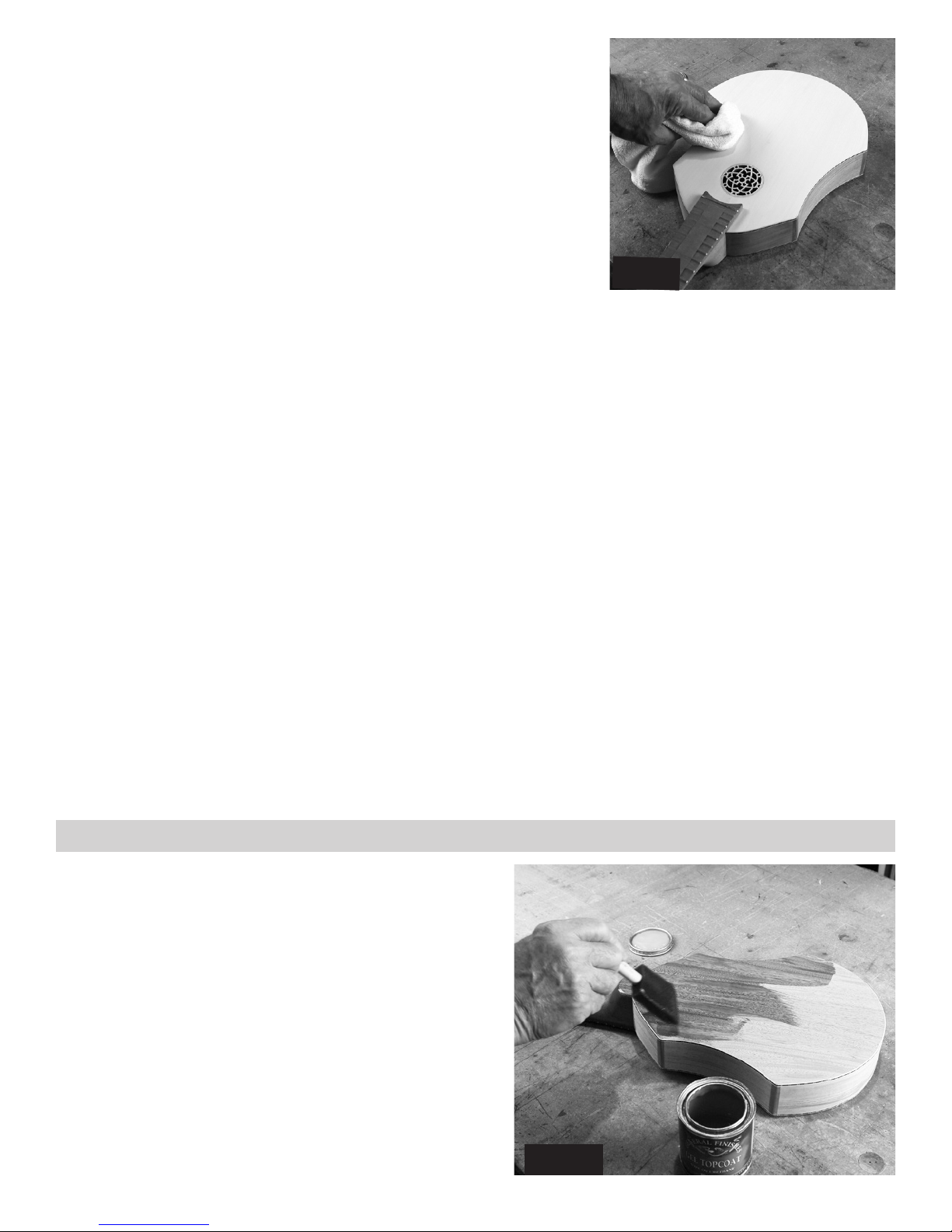
_____63. Use a clean cotton cloth (old t-shirt) to apply each
successive coat of finish (fig 63). No need for a brush or foam
applicator from here on! Now your goal is to apply a very even
thin coat to the entire surface. This is not difficult or time-consuming, but you’ll need good lighting to see the results as you
work. Once you have wetted an area, go back over it with long
strokes to smooth the fresh gel.
Here again, you must resist the urge to apply too much finish.
Just a thin film is all you want. It may not look like you are accomplishing much, but it will look nicer with each successive
coat. Thick coats tend to become uneven, and to take a long
time to dry.
fig 62
fig 63
These wiped-on applications will dry more quickly than the first coat because the wood pores are already sealed. If
you are working in a warm dry environment, it might be ready for fine sanding again in 3-4 hours. Test it by touch,
as mentioned above.
THAT’S IT! This is all there is to our simple finishing system. You just repeat step 62 until you like the results.
We recommend a minimum of 3 coats of finish to give a good protective seal on the instrument. After that, it’s all
cosmetics. NOTE: If you wish to add other decorations to the instrument (decals, paints, etc.), it is smart to do that
work between layers of gel finish. This will seal the decorations permanently to the instrument.
2 7.
Page 28
INSTALLING THE HARDWARE
Tools Required for This Stage
Masking Tape Pencil
Electric Drill 1/16” drill bit
#1 Phillips Screwdriver Masking Tape
CA Glue or Epoxy Ruler
180 grit Sandpaper Chisel
Small Triangle File
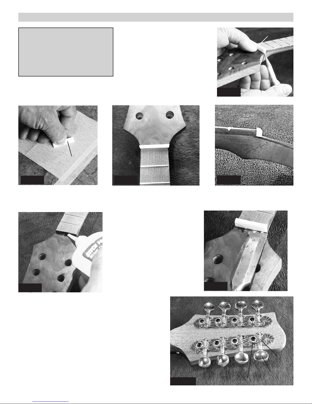
_____64. You are finally ready for the
final phase! We’ll begin by shaping and
installing the nut at the end of the fingerboard.
The nut is a little longer than necessary,
so if you stand it in place, you can trace
the shape of the neck underneath each
end with a sharp pencil (fig 64a). It looks most professional to trim the nut to
match the curve of the wood below it.
180 grit
Sand
paper
Nut
fig 64b
fig 64c
Nut
fig 64a
fig 64d
We like to tape a sheet of 180 grit sandpaper to the work table (fig 64b) so you can sand the ends of the nut to your
pencil lines, and then round over the top edge that faces the peghead (figs 64c and 64d).
When you have it shaped to your liking,
use CA glue or 5-minute epoxy to glue
it in place at the end of the fingerboard
(fig 64e). We like CA glue because we
can just hold the nut in place until it
dries (a minute or so).
After the glue hardens, you can use
a chisel to chip off any excess that
squeezed out onto the peghead (Fig
chisel
64f). Glue does not adhere well to a
finished surface, so it should be easy to
fig 64e
chip off.
fig 64f
If you goof up on placing the nut, you can just tap it loose,
clean off the original glue residue, and try again.
_____65. Find the geared tuners and push them into the back
of the peghead, being careful to orient them on the proper
sides (fig 65a).
Notice that the buttons with the worm gears are situated closer to the end of the instrument than the posts with ring gears.
This is important for longevity and smooth operation of the
tuners because we want the string tension to pull the gears
together instead of apart over time, keeping them operating
smoothly.
28.
fig 65a
Worm
Gear
Button
Ring Gear
Page 29

Push the bushings into the holes around the posts on the front side
(fig 65b). These fit rather tightly, so you may need to use a small
tool to push them in fully.
Use the 1/16” drill bit to make pilot holes for the tiny screws that
hold the gear plate firmly to the back side of the peghead. Be
careful to drill only as deep as the length of the screws. We like
to put tape around the drill bit to mark the maximum depth (fig
65c).
Then install the screws, using a #1 size Phillips screwdriver (fig
65d).
fig 65c fig 65d
_____66. The easiest way to line up the tail piece with the finger-
board is to hold a straight-edge against each side of the fingerboard
and mark its position on a piece of masking tape at the tail end of
the soundboard (fig 66a).
This gives you the outside parameters. If you center the tailpiece
between those marks, the strings will be nicely centered on the fingerboard (66b).
fig 65b
Use the same 1/16” drill bit to make pilot holes for the screws that
hold the tailpiece in place (fig 66c).
fig 66b fig 66c
fig 66a
29.
Page 30

_____67. The Nut and Bridge need to be notched
to hold the strings in the proper positions (fig
67a). It is best to use a metric ruler for marking
these small measurements, as shown in fig 67b.
fig 67b
fig 67a
Use a small triangle file for this notching (unless you have nut
files to match the string gauges). We bought an inexpensive set
of needle files at the hardware, and it includes a nice triangle file
for this purpose (fig 67c & 67d). Note that the bass string pairs
are separated a little further apart than the treble string pairs because the bass strings are the fatter wound strings.
Nut
Bridge
fig 67c fig 67d
HINT: File the notches only about 1 mm deep at first. Once the strings are in place, you may need to file deeper
notches to lower the strings, as instructed toward the end of the next step.
_____68. Now you are ready to install the strings! Begin by sliding the smooth metal cover off the back of the
tailpiece (fig 68a).
We like to begin with one of the fattest bass C strings and one of the lightest treble A strings, and installing them in
the outermost positions on each side of the instrument. These two strings can hold the bridge centered on the instrument, making it a little easier to install the remaining strings, in order.
NOTE: Your string set has two optional
strings included to provide octave tuning at the low C and G positions. It you
want to use this option, we suggest placing the plain C and G strings to the left
Low C
High A
of the wound ones in fig 68b.
fig 68a
Hook the looped end of the string over
the proper hook in the tailpiece, as illustrated in fig 68b. Notice that there are
some extra hooks aiming sideways on
the tailpiece. You can disregard those
and just use the eight vertical hooks for
your complete string set, as shown.
30.
fig 68b
Page 31

fig 68c
The strings are longer than they need to be, so you can pull most of the slack
through the hole in the tuning post before starting to turn the tuning button.
Leave enough slack string across the instrument so that there will be 3-4 wraps
of string around the post before the string becomes taut (fig 68)c.
CAUTION: The correct way to turn the buttons is to make the string fall
to the inside of the peghead, as shown in figure 68d. If you don’t turn them
properly, the strings will rub against neighboring posts and be difficult to tune.
Once the strings are installed, you will likely have some detail work yet ahead
to make the instrument easy to play. You want the strings to hang approximately the heights shown in figure 68e. This is called “setting up” the instrument.
BRIDGE PLACEMENT: This is a “free-floating” bridge, held in place by
the strings. Position it 17-1/4” from the Nut and let the first strings hold it
there. You can make fine adjustments to the intonation of the instrument after
tuning (see back page).
fig 68d
Nut
fig 68e
1st Fret
NOTE: Setting up a new instrument can take several hours,
so put on some relaxing music and take your time!
12th Fret
Start by filing the notches in the nut to get the clearance over the first fret at about 1/32”. That means you should just
be able to slide a credit card between the string and the first fret. Do this for each string individually.
If you file too deeply, the string will buzz against the first fret. In that case, you’ll need to loosen the strings, tap the
nut off the instrument and re-glue it with CA glue. Generally, the new glue is enough to raise the nut enough to stop
the buzz.
Once you have the proper gap at the first fret, work on filing notches in the bridge to lower the strings at the 12th
fret. The 12th fret is the midpoint of the vibrating length, so filing a notch 1/16” deeper in the bridge will lower the
string 1/32” (half as much) at the midpoint. If you need more than that much adjustment, it would be easier to sand
the bottom of the bridge to lower the overall height of all the strings at once.
Conversely, if all the strings are too low to begin with, the easiest solution is to glue a shim under the bridge to raise
all the strings at the same time.
CONGRATULATIONS! We hope you have enjoyed building this kit and that you have many years of pleasure from
playing it. Please let us know if you have suggestions for improving this project. We often get our best ideas from
the customers who build our kits.
31.
Page 32

MUSICMAKERS
PO BOX 2117
Stillwater, MN 55082
651-439-9120
www.harpkit.com
FINE ADJUSTMENTS
You may find the 17-1/4” bridge
location to be slightly off for
good intonation in the highest frets. This is caused by the
amount of stretching required
of the strings when they are
pushed down against the frets.
You can correct for this as follows, using an electronic tuner
for checking accurate pitches:
Check the pitch of each string at
the 12th fret to make sure they
sound exactly one octave above
the open string.
If the fretted pitch is slightly
higher than an octave, slide
the bridge back toward the tail
piece a little bit.
If the 12th fret pitch is slightly
lower than a perfect octave,
then slide the bridge up a little
bit toward the soundhole.
If you’d like to install a strap on the instrument, we
have straps and mounting buttons available at Musicmakers. The mounting buttons can be positioned
as shown in figure 69, with one button replacing the
bottom screw on the tailpiece, and the other resting
on the curved heel of the neck.
fig 69
 Loading...