

Music & Lights ProLights Tribe JETSPOT4Z User Manual
JETSPOT4Z
180W MOVING SPOT WITH ZOOM AND CMY
USER MANUAL
MANUALE UTENTE
EN - IT

All rights reserved by Music & Lights S.r.l. No part of this instruction manual may be
reproduced in any form or by any means for any commercial use.
In order to improve the quality of products, Music&Lights S.r.l. reserves the right to modify the
characteristics stated in this instruction manual at any time and without prior notice.
All revisions and updates are available in the ‘manuals’ section on site www.musiclights.it
REV.02-06/18

JETSPOT4Z
1
TABLE OF
CONTENTS
Safety
General instructions
Warnings and installation precautions
1 Introduction
1. 1 Description
1. 2 Technical specications
1. 3 Operating elements and connections
2 Installation
2. 1 Mounting
3 Functions and settings
3. 1 Operation
3. 2 Basic
3. 3 Menu structure
3. 4 Linking
3. 5 DMX address
3. 6 DMX mode
3. 7 DMX addressing
3. 8 DMX control
3. 9 Colors and gobos
3. 10 Fixture Settings
Movement
Screen
Fixture
Auto and Manual test
3. 11 Advanced
3. 12 Fixture information
3. 14 Operations in automatic mode
Master/Slave
Sequence
Speed
3. 14 Connection of the DMX line
3. 15 Construction of the DMX termination
2
2
3
3
5
6
7
7
8
10
10
10
10
12
15
16
16
16
16
17
17
18
18
18
18
19
19
20
Packing content
4 Maintenance
4. 1 Maintenance and cleaning the unit
4. 2 Fuse replacement
4. 3 Trouble shooting
• JETSPOT4Z
• Mount bracket
• User manual
20
21
21
2
WARNING! Before carrying out any operations with the unit, carefully read this instruction
manual and keep it with cure for future reference. It contains important information about
the installation, usage and maintenance of the unit.
JETSPOT4Z
SAFETY
General instruction
• The products referred to in this manual conform to the European Community Directives and are therefore marked with .
• The unit is supplied with hazardous network voltage (230V~). Leave servicing to skilled personnel only.
Never make any modications on the unit not described in this instruction manual, otherwise you will
risk an electric shock.
• Connection must be made to a power supply system tted with ecient earthing (Class I appliance according to standard EN 60598-1). It is, moreover, recommended to protect the supply lines of the units
from indirect contact and/or shorting to earth by using appropriately sized residual current devices.
• The connection to the main network of electric distribution must be carried out by a qualied electrical
installer. Check that the main frequency and voltage correspond to those for which the unit is designed
as given on the electrical data label.
• This unit is not for home use, only professional applications.
• Never use the xture under the following conditions:
- in places wet;
- in places subject to vibrations or bumps;
- in places with an ambient temperature of over 45°C.
• Make certain that no inammable liquids, water or metal objects enter the xture.
• Do not dismantle or modify the xture.
• All work must always be carried out by qualied technical personnel. Contact the nearest sales point for
an inspection or contact the manufacturer directly.
• If the unit is to be put out of operation denitively, take it to a local recycling
plant for a disposal which is not harmful to the environment.
Warnings and installation precautions
• If this device will be operated in any way dierent to the one described in this manual, it may suer
damage and the guarantee becomes void. Furthermore, any other operation may lead to dangers like
short circuit, burns, electric shock, etc.
• Before starting any maintenance work or cleaning the projector, cut o power from the main supply.
• Always additionally secure the projector with the safety rope. When carrying out any work, always comply scrupulously with all the regulations (particularly regarding safety) currently in force in the country
in which the xture’s being used.
• For inside use only. Not designed for outside use.
• The minimum distance between the xture and surrounding walls must be more than 50 cm and the
air vents at the housing must not be covered in any case.
• Install the xture in a well ventilated place.
• Keep any inammable material at a safe distance from the xture.
• The maximum temperature that can be reached on the external surface of the tting, in a thermally
steady state, is high. After power o, please cool down over 15 minutes.
• Shields, lenses or ultraviolet screens shall be changed if they have become damaged to such an extent
that their eectiveness is impaired.
• The lamp (LED) shall be changed if it has become damaged or thermally deformed.
• Never look directly at the light beam. Please note that fast changes in lighting, e. g. ashing light, may
trigger epileptic seizures in photosensitive persons or persons with epilepsy.

JETSPOT4Z
3
- 1 - INTRODUCTION
1.1 DESCRIPTION
JETSPOT4Z is a 180W 6800K LED spot luminaire designed to replace a 700W discharge xture in theatre,
concert and Venues. Its compact sizes allow the use of this luminaire in venues with low ceiling without
renouncing to zoom.
Its custom optical system delivers a consistent output with a at eld and crisp gobo projection right
through the massive 8° to 40° zoom range.
1.2 TECHNICAL SPECIFICATIONS
LIGHT SOURCE
• Source: 180W High Power White LED
• CT: 6800K
• CRI: 68
• Luminous Flux: 7518lm
• Lux: 8°- 25200 lux; 40° -3250lux @3m
• Lux: 8°- 2268 lux; 40° - 292lux @10m
• Source Life Expectancy: >30.000 h
OPTICS
• Zoom: 8-40° motorized linear zoom
• Lens Type: HQ glass lens optics
• Focus: motorized
COLOR SYSTEM
• Color Mixing: CMY color system on 3 gradually fading color wheels
• CTC: On wheel: 2500K and 3200K + CTB
• Color Wheel: 6 dichroic lters+Open on 3 independent color wheels
DYNAMIC EFFECTS
• Rotating Gobos: 7 Rotating gobos+Open, Interchangeable, Indexing
• Gobo Size: 26,9 mm - img 23 mm - 0,3 mm
• Fixed gobos: 8 Fixed gobos+Open, Interchangeable
• Gobo Size: 29,8 mm - img 23 mm - 0,3 mm
• Circular Prism: 3f with bi-directional rotation, Indexing
• Frost: Linear 0-100% frost lter
• Iris: 5 - 100% motorized linear iris
• Auto Mode: Built-in programs with execution speed adjustment
BODY
• Pan Angle: 540°
• Tilt Angle: 270°
• Pan/Tilt Resolution: 8/16 bit
• Feedback: Automatic repositioning after accidental movement
• Body: Aluminium structure with hi-resistance polycarbonate cover
• Body Color: Black
4
JETSPOT4Z
CONTROL
• Protocols: DMX512, RDM
• DMX Channels: 23/25ch
• RDM: RDM ready for xture remote monitor and settings
• Display: Black TFT high resolution display
• Firmware Upgrade: Yes, via USB-DMX interface (UPBOX1) not included
• Master/Slave: for synchronized operation of more units linked in a chain
ELECTRONICS
• Dimmer: Linear 0~100% electronic dimmer
• Strobe/Shutter: 0 - 30 Hz, electronic
• Battery Backup: Battery backup for user operation without connecting to the main power
• Operating Temperature: -10° ~ +45°
• Flicker: Flicker free operation
ELECTRICAL
• Power Supply: 100-240V – 50/60Hz
• Power Consumption (at 230V): 250W
• Power Consumption (at 120V): 252W
• Output (at 230V): 14 units on a single power line
• Output (at 120V): 8 units on a single power line
PHYSICAL
• Cooling: Forced air with low noise fan
• Suspension And Fixing: Any position with “quick-lock” omega brackets
• Pan/Tilt Lock: Pan and Tilt locking for transportation and maintenance
• Signal Connection: 3p+5p in/out
• Power Connection: PowerCON in/out
• IP: 20
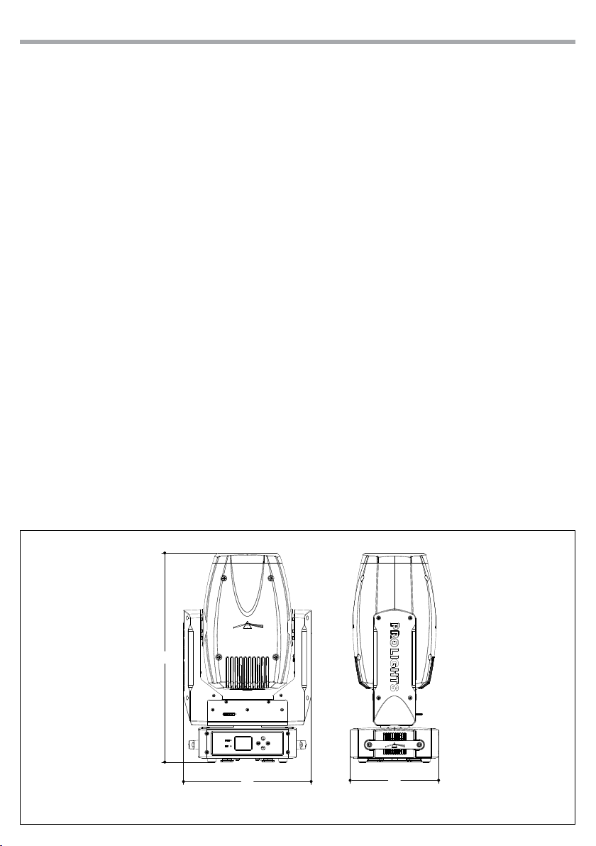
• Dimensions (WxHxD): 332x544x230mm
• Weight: 18,6kg
21,41in
544mm
332mm
13,07in
Technical drawing
230mm
9,05in
Fig.1

1.3 OPERATING ELEMENTS AND CONNECTIONS
A
1
2
34
View A
10
11
9
7
8
JETSPOT4Z
B
5
1. MOVING HEAD
2. ROTARY ARM
3. CONTROL PANEL with TFT
display and 4 button used
to access the control panel
functions and manage them.
4. LED INDICATOR
5. DMX OUT (5-pole XLR):
1 = ground, 2 = DMX-, 3 =
DMX+, 4 N/C, 5 N/C
6. DMX OUT ( 3-pole XLR): 1 =
ground, 2 = DMX -, 3 = DMX +
7. DMX IN (5-pole XLR):
1 = ground, 2 = DMX-, 3 =
DMX+, 4 N/C, 5 N/C
8. DMX IN (3-pole XLR): 1 =
ground, 2 = DMX -, 3 = DMX +
9. MAIN FUSE HOLDER: replace
a burnt-out fuse by one of the
same type only.
10. POWER OUT: (PowerCON OUT)
to connect multiple units in
series.
11. POWER IN (PowerCON IN):
for connection to a socket
(100-240V~/50-60Hz) via the
supplied mains cable.
View B
5
6
Fig.2

6
JETSPOT4Z
- 2 - INSTALLATION
2.1 MOUNTING
The JETSPOT4Z may be set up on a solid and even surface. By means of the xing facilities of the baseplate,
the unit can also be mounted upside down to a cross arm. The base plate is shown in g.3. For xing, stable
mounting clips are required. According to the gure, the bolts of the brackets are placed into the openings
provided in the base plate and turned clockwise until they lock (to the stop). Always ensure that the unit
is rmly xed to avoid vibration and slipping while operating. The mounting place must be of sucient
stability and be able to support a weight of 10 times of the unit’s weight. When carrying out any installation, always comply scrupulously with all the regulations (particularly regarding safety) currently in force
in the country in which the xture’s being used. Always additionally secure the projector with the safety
rope from falling down. For this purpose, fasten the safety rope at a suitable position so that the maximum
fall of the projector will be 20 cm.
SAFETY
CABLE
OMEGA
BRACKETS
Fig.3
JETSPOT4Z
7
- 3 - FUNCTIONS AND SETTINGS
3.1 OPERATION
Connect the supplied main cable to a socket (100-240V~/50-60Hz). The unit will run built-in program to
reset all motors to their home position. Shortly after that the JETSPOT4Z is ready for operation. To switch
o, disconnect the mains plug from the socket. For a more convenient operation it is recommended to
connect the unit to a socket which can be switched on and o via light switch.
3.2 BASIC
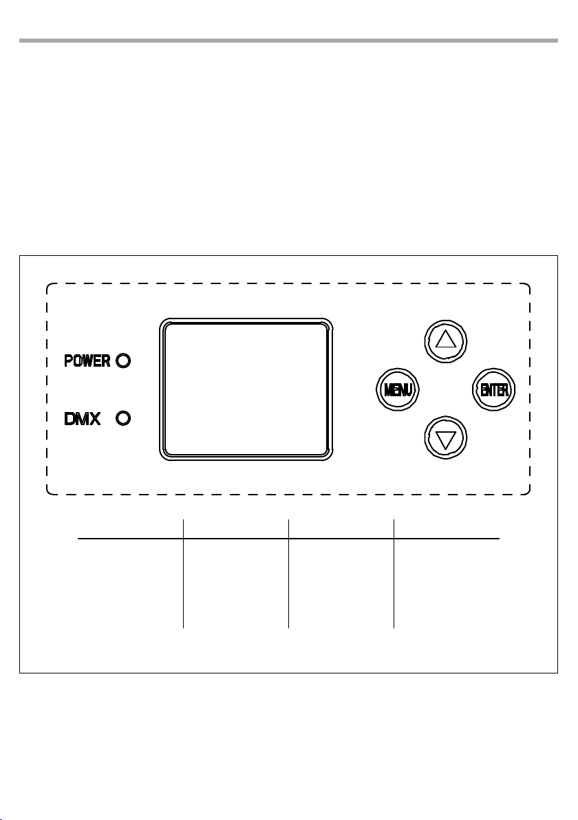
The control panel of JETSPOT4Z has a display and 4 buttons for the complete programming and management of the projector menu (g.4).
UP DOWN MENU ENTER
Increases the value
displayed or passes to
the previous item in a
menu
Decreases the value
displayed or passes to
the next item in the
menu
To enter in the main
menù or to return to the
top level
Conrms the displayed
value, or activates the
displayed function, or
enters the successive
menu
Fig.4 - Functions of the buttons

8
3.3 MENU STRUCTURE
MENU
CONNECT
1
2 SET UP
ð
ð
DMX Address
DMX Mode
Movement
Screen
Fixture
LED Frequency
Auto Test
Manual Test
JETSPOT4Z
Value (1-512)
ð
Basic 25CH
ð
Basic 23CH
Pan Reverse
ð
Tilt Reverse
Pan Feedback
Tilt Feedback
Backlight
ð
Flip Display
Warn Cue
Key Lock
Fan mode
ð
Temperature unit
600Hz
ð
1200 Hz
2000 Hz
4000 Hz
6000 Hz
25KHz
Auto Test
ð
Pan
ð
Pan Fine
Tilt
Tilt Fine
P/T Speed
Dimmer
Shutter
Color1
Color2
Color3
Cyan
Magenta
Yellow
Gobo1
RGobo1
Gobo2
Prism Rot
Focus
Zoom
Frost
Iris
YES/NO
ð
ON
ð
10s
20s
30s
YES/NO
ð
ON/OFF
ð
YES/NO
ð
Auto/High
ð
C°/F°
ð
Value (000-255) for each function
ð

JETSPOT4Z
9
3 ADVANCED
4 INFORMATION
5 STAND ALONE
Reset
ð
Adjust
ð
Factory Reload
ð
Fixture Time
ð
Temperature 58 °C
Fans Speed **%
ð
ð
ð
ð
ð
Software Ver.
UID 15D0021C****
Play
ð
ð
All
Pan
Tilt
Cyan&Color1
Magenta&Color2
Yellow&Color3
Gobo1
Gobo2
Prism
Focus
Zoom
Frost
Iris
Pan Oset
Tilt Oset
Cya&C1 Oset
Mag&C2 Oset
Yell&C3 Oset
Gobo1 Oset
RGobo1 Oset
Gobo2 Oset
Prism Oset
Focus Oset
Zoom Oset
Frost Oset
Iris Oset
YES/NO
0-9999
DISP- V0.1
CTR1-XY- V0.1
CTR2-MOTOR-V0.1
CTR3-MOTOR-V0.1
CTR4-MOTOR-V0.1
Master/Slave
Sequence
Speed
Master
ð
Slave
Show 1
ð
Show 2
Show 3
Show 4
Value (001-100%)
ð

10
JETSPOT4Z
3.4 LINKING
Several units may be interconnected in order to control all further slave units to the same eect of the
master unit.
1. Connect the DMX OUT of the master unit via 3/5-pole XLR cable to the DMX IN of the rst slave unit.
2. Connect the DMX OUT of the rst slave unit to the DMX IN of the second slave unit, etc. until all units
are connected in a chain.
3.5 DMX ADDRESS
To enter the DMX mode, follow these steps:
• Press the ENTER button to access the main menu.
• Press the UP/DOWN button to scroll the menu, select the Connect icon, then press the ENTER button to
enter the next menu.
• Press the UP/DOWN button to scroll through the menu, select the Address and press the ENTER key.
• Press the arrow keys to select the desired value (001-512).
• Press the ENTER key to conrm the setting.
• Press the MENU button repeatedly to exit the menu and save changes.
3.6 DMX MODE
The JETSPOT4Z has more DMX channel congurations which can be accessed from the control panel.
• Press the ENTER button to access the main menu.
• Press the UP/DOWN button to scroll the menu, select the Connect icon, then press the ENTER button to
enter the next menu.
• Press the UP/DOWN button to scroll through the menu, select DMX Mode and press the ENTER button to
enter the next menu.
• Press the UP/DOWN button to scroll through the menu, select the mode and press ENTER to conrm
your choice.
• Press the MENU button repeatedly to exit the menu and save changes.
The unit is equipped with 3/5-pole XLR connections.
3.7 DMX ADDRESSING
For operation via light control unit with DMX512 protocol, is sucient connect the controller to JETSPOT4Z. To able to operate the JETSPOT4Zwith a light controller, adjust the DMX start address for the rst
a DMX channel. If e. g. address 33 on the controller is provided for controlling the function of the rst DMX
channel, adjust the start address 33 on the JETSPOT4Z. The other functions of the light eect panel are
then automatically assigned to the following addresses.
An example with the start address 33 is shown below
Numero
canali DMX
Indirizzo di
start (esempio)
Indirizzo DMX
occupati
Prossimo indirizzo di start
possibile per unità n°1
Prossimo indirizzo di start
possibile per unità n°2
Prossimo indirizzo di start
possibile per unità n°3
23 33 33-56 57 80 103
25 33 33-58 59 84 109
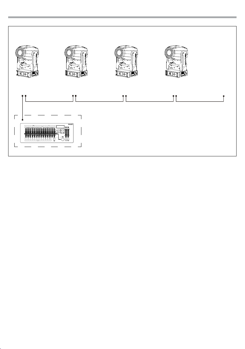
DMX512 Controller
JETSPOT4Z
11
DMX Address: 103DMX Address: 57DMX Address: 33 DMX Address: 80
. . . . . . . . . . . .
Fig.6 - Example 23 DMX channels conguration

12
3.8 DMX CONTROL
JETSPOT4Z
STANDARD EXTENDED
FUNCTION
23 ch 25 ch
1 1 PAN 000 - 255
2 2 PAN Fine 000 - 255
2 3 TILT 000 - 255
4 4 TILT Fine 000 - 255
5 5 PAN/TILT Speed 000 - 255
6 6 Dimmer 000 - 255
7 Dimmer Fine 000 - 255
SHUTTER
Shutter closed
No function (shutter open)
7 8
8 9
9 10
10 11
11 12
12 13
13 14
Shutter eect slow to fast
No function (shutter open)
Pulse-eect in sequences
No function (shutter open)
Random strobe eect slow to fast
No function (shutter open)
COLOR1
Open
Color1-1(UV)
Color1-2 and Color2-2(UV and BLU)
Color1-2(BLU)
COLOR2
Open
Color2-1(ORANGE)
Color2-1 and Color2-2(ORANGE and RED)
Color2-2(RED)
COLOR3
Open
Color3-1(COLOR TEMPERATURE ORANGE FILTER)
Color3-1 and Color3-2(COLOR TEMPERATURE ORANGE FILTER and GREEN)
Color3-2(GREEN)
CYAN
0~100% (When Color1 Open)
MAGENTA
0~100% (When Color2 Open)
YELLOW
0~100% (When Color2 Open)
DMX
Value
000 - 031
032 - 063
064 - 095
096 - 127
128 - 159
160 - 191
192 - 223
224 - 255
000 - 020
021 - 040
041 - 060
061 - 255
000 - 020
021 - 040
041 - 060
061 - 255
000 - 020
021 - 040
041 - 060
061 - 255
000 - 255
000 - 255
000 - 255

JETSPOT4Z
13
STANDARD EXTENDED
23 ch 25 ch
14 15
15 16
16 17
FUNCTION
ROTATING GOBO WHEEL
Open
Position 1
Position 2
Position 3
Position 4
Position 5
Position 6
Position 7
Position 1 Shaking slow to fast
Position 2 Shaking slow to fast
Position 3 Shaking slow to fast
Position 4 Shaking slow to fast
Position 5 Shaking slow to fast
Position 6 Shaking slow to fast
Position 7 Shaking slow to fast
Fast to Slow(Forward Spin)
Stop (Stop Rotation)
Slow to Fast(Revers Spin)
GOBO ROTATION
Positioning from 0 - 360 degrees (Indexing)
Fast to Slaw
Stop
Slow to Fast
FIXED GOBO
Open
Position 1
Position 2
Position 3
Position 4
Position 5
Position 6
Position 7
Position 8
Position 1 Shaking slow to fast
Position 2 Shaking slow to fast
Position 3 Shaking slow to fast
Position 4 Shaking slow to fast
Position 5 Shaking slow to fast
Position 6 Shaking slow to fast
Position 7 Shaking slow to fast
Position 8 Shaking slow to fast
Fast to Slaw (Forward Spin)
Stop (Stop Rotation)
Slow to Fast (Revers Spin)
DMX
Value
000 - 005
006 - 010
011 - 015
016 - 020
021- 025
026 - 030
031 - 035
036 - 040
041 -055
056 - 070
071 - 085
086 - 100
101 - 115
116 - 130
131 - 145
146 - 199
200 - 201
202 - 255
000 -191
192 - 221
222 - 225
226 - 255
000 - 005
006 - 009
010 - 013
014 - 017
018 - 021
022 - 025
026 - 029
030 - 033
034 - 037
038 - 051
052 - 065
066 - 079
080 - 093
094 - 107
108 - 121
122 - 135
136 - 149
150 - 201
202 - 203
204 - 255
 Loading...