

Musica 2000 User Manual
OPERATING GUIDEOPERATING GUIDE
ESCORT
™
2000
150 WATT POWERED MIXER
ESCORT
™
2000
150 WATT POWERED MIXER
2
Intended to alert the user to the presence of uninsulated “dangerous voltage” within the product’s
enclosure that may be of sufficient magnitude to constitute a risk of electric shock to persons.
Intended to alert the user of the presence of important operating and maintenance (servicing)
instructions in the literature accompanying the product.
CAUTION: Risk of electrical shock — DO NOT OPEN!
CAUTION: To reduce the risk of electric shock, do not remove cover. No user serviceable parts inside. Refer
servicing to qualified service personnel.
WARNING: To prevent electrical shock or fire hazard, do not expose this appliance to rain or moisture. Before
using this appliance, read the operating guide for further warnings.
Este símbolo tiene el propósito, de alertar al usuario de la presencia de “(voltaje) peligroso” sin aislamiento dentro de la caja del producto y que puede tener una magnitud suficiente como para constituir
riesgo de descarga eléctrica.
Este símbolo tiene el propósito de alertar al usario de la presencia de instruccones importantes sobre la
operación y mantenimiento en la información que viene con el producto.
PRECAUCION: Riesgo de descarga eléctrica ¡NO ABRIR!
PRECAUCION: Para disminuír el riesgo de descarga eléctrica, no abra la cubierta. No hay piezas útiles dentro.
Deje todo mantenimiento en manos del personal técnico cualificado.
ADVERTENCIA: Para evitar descargas eléctricas o peligro de incendio, no deje expuesto a la lluvia o humedad
este aparato Antes de usar este aparato, Iea más advertencias en la guía de operación.
Ce symbole est utilisé dans ce manuel pour indiquer à l’utilisateur la présence d’une tension dangereuse
pouvant être d’amplitude suffisante pour constituer un risque de choc électrique.
Ce symbole est utilisé dans ce manuel pour indiquer à l’utilisateur qu’il ou qu’elle trouvera d’importantes
instructions concernant l’utilisation et l’entretien de l’appareil dans le paragraphe signalé.
ATTENTION: Risques de choc électrique — NE PAS OUVRIR!
ATTENTION: Afin de réduire le risque de choc électrique, ne pas enlever le couvercle. Il ne se trouve à l’intérieur
aucune pièce pouvant être reparée par l’utilisateur. Confiez I’entretien et la réparation de l’appareil à un réparateur
Peavey agréé.
AVERTISSEMENT: Afin de prévenir les risques de décharge électrique ou de feu, n’exposez pas cet appareil à la
pluie ou à l’humidité. Avant d’utiliser cet appareil, lisez attentivement les avertissements supplémentaires de ce
manuel.
Dieses Symbol soll den Anwender vor unisolierten gefährlichen Spannungen innerhalb des Gehäuses
warnen, die von Ausreichender Stärke sind, um einen elektrischen Schlag verursachen zu können.
Dieses Symbol soll den Benutzer auf wichtige Instruktionen in der Bedienungsanleitung aufmerksam
machen, die Handhabung und Wartung des Produkts betreffen.
VORSICHT: Risiko — Elektrischer Schlag! Nicht öffnen!
VORSICHT: Um das Risiko eines elektrischen Schlages zu vermeiden, nicht die Abdeckung enfernen. Es befinden
sich keine Teile darin, die vom Anwender repariert werden könnten. Reparaturen nur von qualifiziertem
Fachpersonal durchführen lassen.
ACHTUNG: Um einen elektrischen Schlag oder Feuergefahr zu vermeiden, sollte dieses Gerät nicht dem Regen
oder Feuchtigkeit ausgesetzt werden. Vor Inbetriebnahme unbedingt die Bedienungsanleitung lesen.

3
PEAVEYESCORT™2000 OPERATING GUIDE
Congratulations! You have just purchased the world’s finest packaged sound system, the Peavey Escort 2000
™
. The
Escort’s integrated design allows for ease of transportation, while its user-friendly controls offer ease of operation,
combining to make it the perfect choice for schools, churches, civic organizations, and small musical groups. The Escort
features two 2-way speakers driven by a 5-channel, 150-Watt stereo powered mixer, making it ideal for both vocal and
musical applications. The system also includes a PVi
®
unidirectional (cardioid pattern) dynamic microphone, 2 folding
speaker stands, and all necessary connecting cables. Among many professional features, the mixer includes 60 mm
faders, a 5-band graphic equalizer with FLS®(Feedback Locating System), and digital reverb. The carrying case
provides storage for all the system components with ample room for additional mics and cables. This clever design
incorporates the speakers into the package, allowing the unit to be easily carried or pulled along on its luggage-style
wheels. We think you’ll agree that the Escort 2000 raises portable sound to a new level!
Escort Features:
• Convenient package with luggage-style wheels
• 2-way speaker system with 10” woofer and
piezoelectric horn.
• 5-channel powered mixer
• 4 XLR mic inputs with 15 V phantom power
• 2 stereo line inputs
• 60 mm faders
• High-quality digital reverb
• 150 Watts of output power (75 Watts per channel)
with DDT
™
• Variable-speed cooling fan
• 5-band graphic equalizer with FLS
• 2 folding speaker stands
• 1 PVi cardioid dynamic microphone with cable
• Two 25’ speaker cables
• Storage compartments for microphones, cables and accessories
Table of Contents Page
Quick Setup Guide . . . . . . . . . . . . . . . . . . . . . . . . 4
Setting Up Speakers . . . . . . . . . . . . . . . . . . . . . . . 4
Connecting Microphone(s). . . . . . . . . . . . 5
Connecting CD, Tape,
or Other Line Sources. . . . . . . . . . . . . 5
Connecting Power . . . . . . . . . . . . . . . . . . 5
Setting Controls and Turning Unit On . . . 6
Adjusting Gain and Volume Controls (Faders) . . . 6
Adjusting Tone Controls. . . . . . . . . . . . . . . . . . . . 6
Using the Graphic Equalizer. . . . . . . . . . . . . . . . . 6
Avoiding Acoustic Feedback . . . . . . . . . . . . . . . . 7
Microphone Usage Guidelines . . . . . . . . . . . . . . . 7
Reverb . . . . . . . . . . . . . . . . . . . . . . . . . . . . . . . . . 7
Stereo / Mono Operation . . . . . . . . . . . . . . . . . . . 7
Main and Monitor Operation . . . . . . . . . . . . . . . . 8
Auxiliary Output (AUX OUT) Operation . . . . . . 8
Packing the Escort 2000. . . . . . . . . . . . . . . . . . . . 8
Optional Accessories . . . . . . . . . . . . . . . . . . . . . . 8
Troubleshooting Guide. . . . . . . . . . . . . . . . . . . . . 9
Specifications. . . . . . . . . . . . . . . . . . . . . . . . . . . . 10
ENGLISH

4
Quick Setup Guide
THINK SAFETY FIRST!
Much of the setup of the Escort
™
2000 is similar to the setup of other sound systems, and many aspects require
plain common sense. Safety should always be your first concern. Always use grounded outlets and 3-wire extension
cords. Run sound system cables in a way to prevent the danger of tripping, and tape them down where necessary.
Place the speaker stands on a solid, level surface. Following these guidelines will help prevent personal injury and
equipment damage.
Setting Up Speakers
Place the unit so that the speakers form the upper part of the case. Release the latches by lifting up until the latch
disengages. Remove the speakers from the Escort package.
NOTE: The latches can be closed once the speakers are removed and it is recommended that they be closed to avoid
interference with removal of components and to protect the latch. Close the latch by pushing in until it is flush with the
side of the case, and then down until it locks.
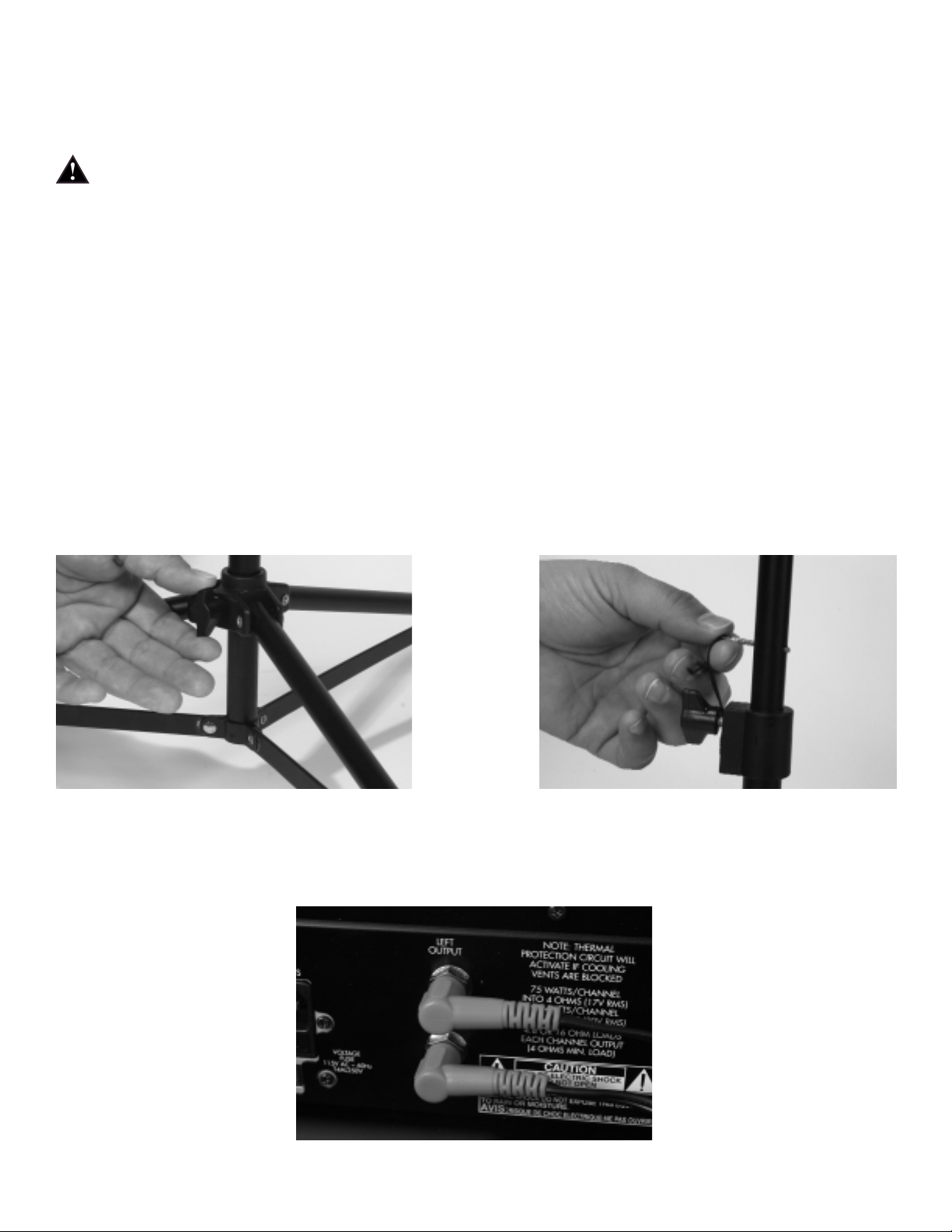
Remove the speaker stands from the case. Be sure the legs on the stands are fully extended to provide a stable base for
the speakers, and are positioned on a level surface. Tighten the thumbscrew on the base so that it is snug, but do not
overtighten (Fig. 1). Raise the speaker stands to the desired height, tighten thumbscrew, and install the safety pin as
shown (Fig. 2).
Fig. 1 Fig. 2
Place speakers on stands and position them so that they will face the audience and face away from the microphones.
Connect speaker cables from the jack on the lower front of each speaker to the powered mixer, connecting the left
speaker to the LEFT OUTPUT and the right speaker to the RIGHT OUTPUT jacks on the rear panel of the unit (Fig. 3).
Fig. 3
Warning! Do not connect additional speakers to the Escort 2000 powered mixer. The system speakers provide the
optimal load for the amplifier.
5
Connecting Microphone(s)
The Escort™2000 powered mixer is designed to work with any good-quality, balanced, dynamic or condenser
microphone such as the PVi
®
microphone supplied. Connect the microphone(s) to the XLR (3- pin) input connectors as
shown (Fig. 4). When using more than one mic, try to connect them to channels in the same order as they appear on
stage to make them easier to control.
Fig. 4
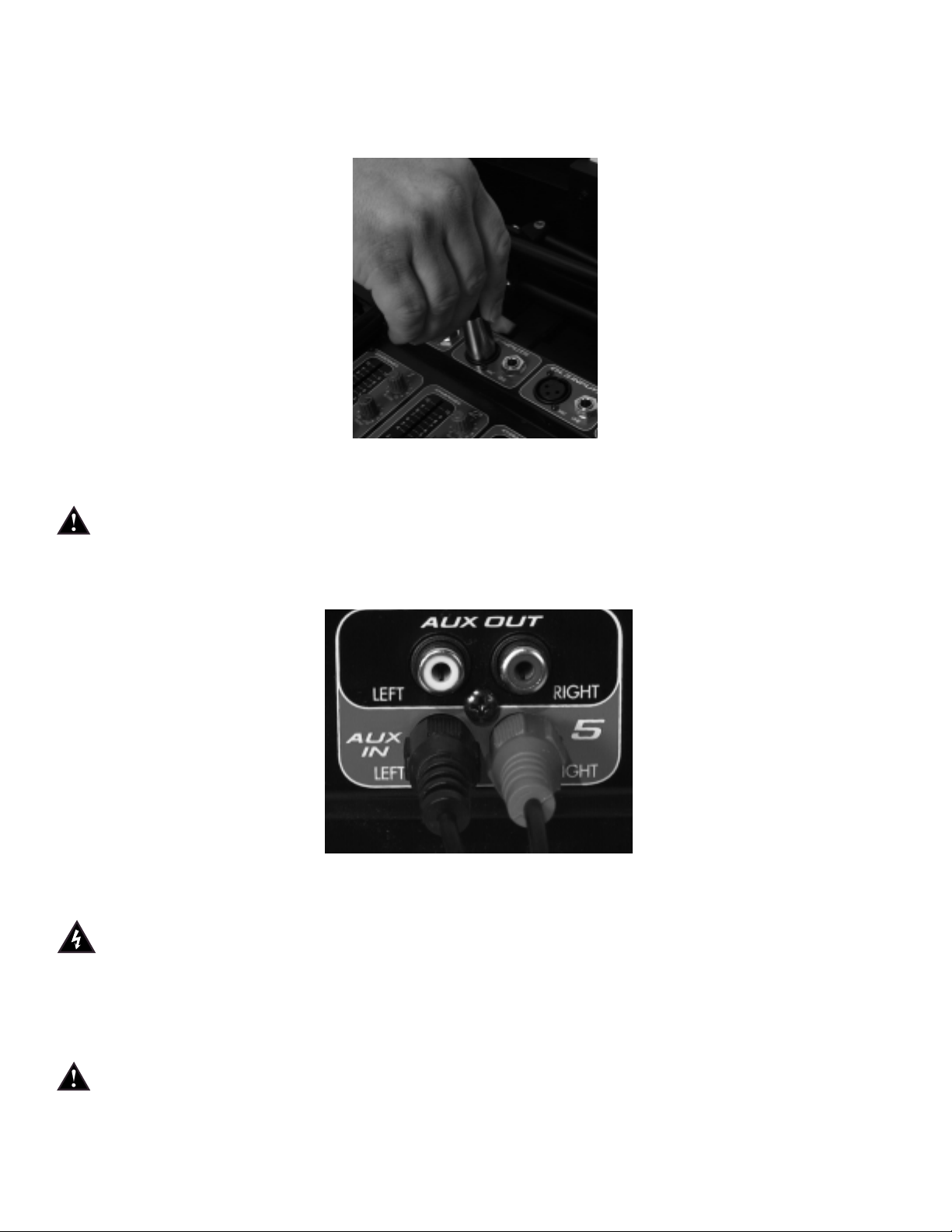
Connecting CD, Tape, or Other Line Sources
Connect a CD or tape player to the CHANNEL 5 auxiliary input connectors (AUX IN) as shown (Fig 5). If you
wish to connect an additional tape machine, CD or other line source to the Escort 2000, CHANNEL 5 also has
stereo line inputs and CHANNELS 1–3 have monaural (MONO) line inputs. Additional cables for connecting to
the Escort 2000 should be readily available at your Peavey dealer. Connecting only to the CHANNEL 4
LEFT/MONO jack automatically converts that channel for mono operation (the sound will come out of both
speakers).
Fig. 5
Connecting Power
Before connecting power, make sure that the power switch is in the OFF position.
Connect the IEC power cord to the receptacle on the back panel of the unit as shown (Fig. 6), and then to a
suitable electrical outlet. If an extension cord is used, be sure that it is a 3-wire cord with ground pin intact to
preserve the safety ground.
NOTE: FOR UK ONLY
If the colors of the wires in the mains lead of this unit do not correspond with the colored markings identifying the
terminals in your plug, proceed as follows: (1) The wire that is colored green and yellow must be connected to the
terminal that is marked by the letter E, the earth symbol, colored green, or colored green and yellow. (2) The wire
that is colored blue must be connected to the terminal that is marked with the letter N or the color black. (3) The
wire that is colored brown must be connected to the terminal that is marked with the letter L or the color red.

6
Fig. 6
Setting Controls and Turning Unit On
Set master controls to around 6 and all other controls to 0. Turn on power by placing the OFF/ON switch, located
adjacent to the IEC cord receptacle (Fig.6), in the ON position.
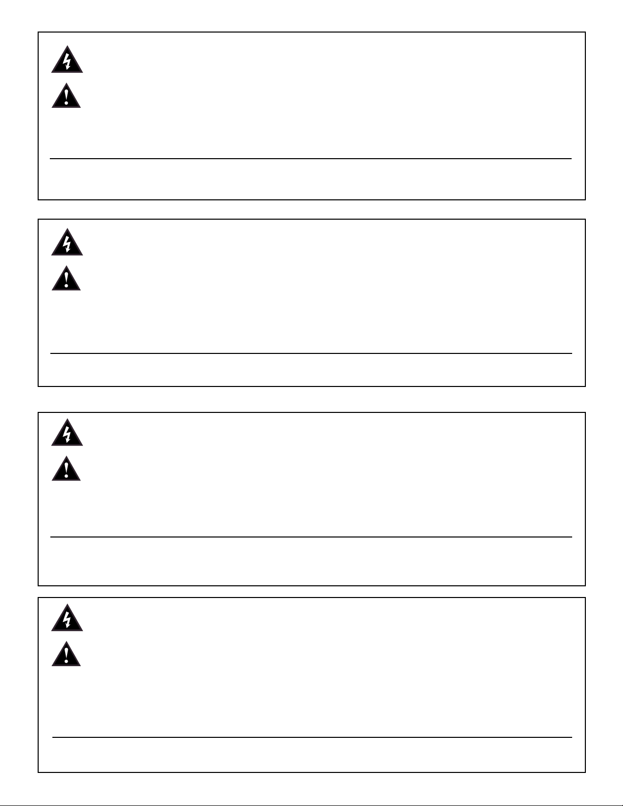
Adjusting Gain and Volume Controls (Faders)
Adjust the channel GAIN controls (Fig. 7) for desired level from the speakers. If the desired level is reached with the
channel GAIN at a low setting (1-3), lower the MASTER VOLUME controls (Fig.8). If the channel GAIN needs to be
set at 9-10 for desired volume, raise the MASTER VOLUME controls. The L and R MASTER VOLUME controls
adjust the left and right speakers.
Adjusting Tone Controls
Adjust the channel BASS and TREBLE controls (Fig. 7) as necessary to achieve desired sound. However, use
moderation in setting channel tone controls. Extreme settings of these controls can adversely affect sound quality.
Large amounts of boost (+) on these controls can also increase the chance of feedback on microphone inputs.
Fig.7 Fig. 8
Using the Graphic Equalizer
Unlike the BASS and TREBLE controls on each channel that adjust only the tone of their own input signals, the 5-band
graphic equalizer adjusts the tonal balance of all the signals going through the powered mixer. This gives the user greater
flexibility in adjusting the sound, but use moderation in making adjustments.

7
The FLS®(Feedback Locating System) LED indicators are invaluable tools in helping to reduce/eliminate feedback. To
use the FLS feature, start by setting all graphic EQ sliders (Fig. 9) to 0. Then, before the audience arrives, increase the
MASTER VOLUME and/or CHANNEL GAIN until feedback occurs. Note which LED illuminates and slightly lower
the corresponding slider. This reduces the gain at the feedback frequency, and can be repeated if necessary to improve
gain before feedback. However, only lower the sliders in small amounts to avoid adversely affecting sound quality.
Fig. 9
Avoiding Acoustic Feedback
Acoustic feedback is the loud howl or squealing sound heard through sound systems as the result of sound from the
speakers re-entering the microphones. Although it does an excellent job of getting the audience’s attention, feedback
should be avoided. When trying to deal with acoustic feedback it is always best to start looking at the placement of the
mics and speakers in the system before resorting to equalization (EQ) adjustment. Make sure that the speakers are
positioned to direct the sound toward the audience and away from the microphones. Position mics as close to the sound
source as reasonable. Moving the mic closer increases the volume of the sound through the system without having to
turn up the gain.
Microphone Usage Guidelines
When practical, a single microphone is preferred. Additional microphones pick up more sound from the speakers and
each mic has to be turned down a little to prevent feedback. However, if you have difficulty balancing the level of
different individuals with one mic, or if you still cannot get sufficient gain, using more mics can offer an advantage.
Giving several singers their own microphones, for example, allows placement of the microphones much closer to each
singer. This increases the volume of the sound at the mic and far outweighs any detrimental effect from using multiple
mics. It also allows the volume of each mic to be adjusted separately for proper balance.
Reverb
Adding reverberation to music can enhance the sound of that music. To add reverb to a microphone, simply turn up the
REVERB control (Fig. 7) on the appropriate input channel. Add reverb in moderation because too much reverb makes
vocals hard to understand. In most cases, it is best not to add reverb to the spoken word.
Stereo / Mono Operation
The Escort
™
2000 powered mixer has two input channels (4 & 5) for stereo line sources. If the speakers are situated so
that most of the audience can hear both speakers (Fig. 10 A), it can be advantageous to run the system in stereo. If the
audience primarily hears just one speaker (Fig. 10 B), or if you are using one speaker for the audience and the other for
the stage performers, then it is best to run the system in mono.
Fig. 10
Stereo
Mono
A B
Stereo
Mono

8
The MODE switch on CHANNEL 5 sets that channel for STEREO or MONO operation. On CHANNEL 4, use the
LEFT input only for MONO operation, or both LEFT and RIGHT inputs for STEREO. Inputs on CHANNEL 1–3 are
MONO. The MODE switch on CHANNEL 5 is also very useful for playing tapes or CDs with “split tracks”. Setting the
switch to MONO allows the signal from a source connected to either the LEFT or RIGHT input to be directed to both
speakers.
Main and Monitor Operation
The Escort
™
2000 can also be used in applications where stage monitoring is required. By operating the mixer in the
mono mode, the right speaker can be used for providing sound to the audience (MAIN) and the left can be used for the
performers (MON). The MASTER VOLUME controls (Fig. 8) allow the volume of these two speakers to be set
independently. These controls are also labeled MAIN and MON for this purpose. If additional sound is required, the
auxiliary output (AUX OUT) can be used to drive an auxiliary monitor amplifier or powered monitor speakers.
Auxiliary Output (AUX OUT) Operation
The AUX OUT is a line-level output from the mixer that can be used for recording, or driving an auxiliary amplifier.
Warning: Connecting a tape machine to the AUX OUT to record while simultaneously connecting the tape machine’s
output into the mixer inputs can create an electronic feedback loop. Connect only the tape machine’s inputs or outputs to
the mixer, never both.
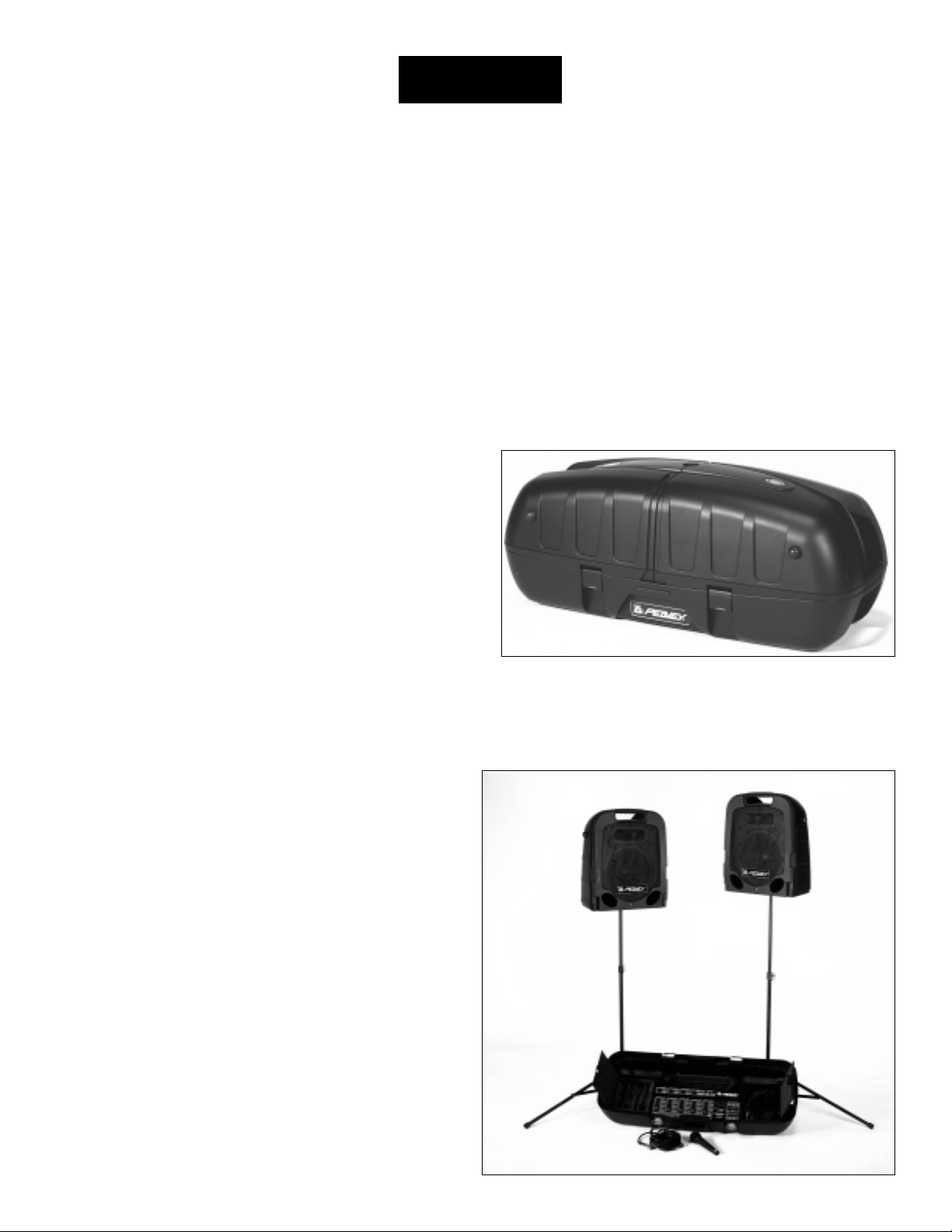
Packing the Escort 2000
One of the Escort’s many benefits is that the entire sound system can be packed inside its easily transportable case (Fig.
11). Begin by folding the speaker stands and securing them into their storage compartment using the two straps. Place
the microphone(s) in their storage compartment, putting the cables in the other compartment or with the speaker stands.
Lay the speakers face down on top of the bottom tray and secure the four latches. The Escort 2000 is now ready to be
carried or pulled on its built-in, luggage-style wheels.
Fig. 11
Optional Accessories (available from Peavey dealers)
Microphone stand(s)
Additional microphones and cables
Microphone wind screens o
Long speaker cables
Tall speaker stands
Audio cables for CD and tape

9
Problem Check Correction
No sound Is power switch on? Turn power switch on.
(no power light) Is line cord connected to live power
outlet? Connect power cord to live outlet.
No sound (power light on) Are MASTER and CHANNEL Adjust both MASTER and CHANNEL GAIN
GAIN controls up? controls upward to desired level. Check speaker
connections. Turn mic switch on. Check mic or
sound source connection.
Fan speed varies This is normal. Speed varies with N/A
audio signal.
Only one speaker works Are speaker cable connectors secure? Fully insert connector and/or swap speaker
cables between left and right speakers and
Mon o li n e so u r c e in t o CH A N N E L4 or 5? outputs to check for damaged cables. Set
CHANNEL 5 MODE switch to MONO or use
LEFT INPUT on CHANNEL 4.
Are both MASTER controls turned up.
Loud howling or squeal from speakers If it goes away when the CHANNEL or Reduce microphone gain. Reposition
MASTER volume controls are lowered, microphone behind or farther from speakers.
it is acoustic feedback. Observe FLS light above EQ and reduce level
of that band.
Sound is distorted Is the CHANNEL GAIN at a very Reduce CHANNEL GAIN and increase
high setting? MASTER VOLUME
Troubleshooting Guide

10
Escort™2000 Specifications:
Output Power: 75 Watts per channel into 4 Ohm load
Frequency Response: 30 Hz to 25 kHz +0/-3 dB measured at 1 Watt
Overload Protection: DDT
™
(Distortion Detection Technology) limits the power amplifier input to prevent clipping
distortion that can damage speakers.
Tone Controls: Bass: 100 Hz +/- 10 dB
Treble: 10 kHz +/- 10 dB
Graphic Equalizer: 5 bands: 100 Hz, 350 Hz, 1 kHz, 3 kHz and 8 kHz
With FLS
®
(Feedback Locating System)
Input Impedance: Mic Input: 2 K Ohms
Line Input: 12 K Ohms
Distortion: Less than 0.8% THD at rated output
Max Gain: 86 dB mic input to speaker output
Signal/Noise Ratio: 85 dB mic input typical
Reverb: Digital
AC Power: 115 VAC 60 Hz or
230 VAC 50/60 Hz
Weight Assembled: 57 lbs.(25.9 Kg)
Dimensions: 14.5" H x 36.75" W x 15.5" D
(36.8H x 93.3W x 39.4D cm)
Speakers: Woofer 10" (254 mm)
Piezoelectric Horn Tweeter
Microphone: Dynamic, Cardioid (Unidirectional)
11
PEAVEY ESCORT™2000 Bedienungsanleitung
Wir freuen uns, dass Sie sich für Peaveys Escort 2000
™
– die innovativste Lösung unter den Kompakt-PA-Systemen –
entschieden haben! Durch sein ultrakompaktes, transportfreundliches Design und die intuitive Bedienbarkeit ist das
Escort-System die ideale Lösung für Schulen, Kirchen und andere Organisationen sowie für kleinere Musikgruppen. Das
Escort-Soundsystem besteht aus zwei 2-Wege-Lautsprechern und einem 5-kanaligen Powermixer mit einer Leistung von
150 Watt stereo und ist damit der Allrounder für alle Arten von Musik und Gesang. Abgerundet wird die Ausstattung
durch ein dynamisches Mikrofon (Modell PVi
®
, Richtcharakteristik Niere), 2 klappbare Lautsprecherhochständer und
alle erforderlichen Verbindungskabel. Zu den professionellen Features des Peavey Escort 2000 zählen u.a. die 60-mmFader der Mixersektion, ein grafischer 5-Band-Equalizer mit FLS
®
(Feedback Locating System) und eine digitale
Halleinheit. Für optimalen Transport sorgt ein geräumiges Case, in dem nicht nur sämtliche Systemkomponenten,
sondern auch zusätzliche Mikros und Kabel Platz finden. Dank seines ausgeklügelten Case-Designs mit integrierten
Lautsprechern und kofferartigen Rollen lässt sich das System nicht nur bequem tragen, sondern auch ziehen. Sie werden
uns also sicherlich zustimmen, wenn wir den Escort 2000 als Innovation unter den mobilen PA-Systemen bezeichnen!
Ausstattung Escort 2000:
• Transportfreundliches Koffersystem mit Rollen
• 2-Wege-Lautsprechersystem mit 10"-Tieftöner und
piezogesteuertem Horn
• 5-kanaliger Powermixer
• 4 XLR-Mikrofon-Eingänge mit 15-V-Phantomspeisung
• 2 Stereo-Line-Eingänge
• 60-mm-Fader
• Hochwertiges Digital-Hall
• 150 Watt Ausgangsleistung (75 Watts pro Kanal) mit DDT
™
• Lüfter mit variabler Geschwindigkeit
• Grafischer 5-Band-Equalizer mit FLS
• 2 klappbare Lautsprecherhochständer
• 1 dynamisches Mikrofon (Modell PVi, Nierencharakteristik) inkl. Kabel
• 2 7,5-m-Lautsprecherkabel
• Platz für Mikrofone, Kabel und weiteres Zubehör
Inhalt Seite
Schnelleinstieg . . . . . . . . . . . . . . . . . . . . . . . . . . . 12
Aufstellen und Anschließen der Lautsprecher . . . . 12
Anschluss eines oder mehrerer Mikrofone 13
Anschluss von CD-Playern, Bandgeräten
oder anderen Line-Zuspielquellen . . . . 13
Anschluss an das Stromnetz . . . . . . . . . . . 14
Grundeinstellung und Inbetriebnahme . . . 14
Einstellung von Gain und Lautstärke (Fader). . . . . 14
Klangeinstellung . . . . . . . . . . . . . . . . . . . . . . . . . . 14
Einsatz des grafischen Equalizers . . . . . . . . . . . . . 15
Akustische Rückkopplungen . . . . . . . . . . . . . . . . . 15
Hinweise zum Umgang mit Mikrofonen . . . . . . . . 15
Hall . . . . . . . . . . . . . . . . . . . . . . . . . . . . . . . . . . . 15
Stereo/Monobetrieb . . . . . . . . . . . . . . . . . . . . . . . 16
Parallelbetrieb als PA- und Monitorsystem . . . . . . 16
AUX-Ausgang (AUX OUT) . . . . . . . . . . . . . . . . . 16
Packen des Escort 2000 . . . . . . . . . . . . . . . . . . . . 16
Optionales Zubehör .................................................17
Erste Hilfe bei Problemen ........................................18
Technische Daten .....................................................19
DEUTSCH
12
Schnelleinstieg
SICHERHEIT GEHT VOR!
Der Aufbau des Escort
™
2000 ist im Wesentlichen mit dem handelsüblicher PA-Systeme vergleichbar und erfordert
kein besonderes Fachwissen. Die Sicherheit sollte allerdings stets an erster Stelle stehen. Betreiben Sie das Gerät
daher ausschließlich an korrekt geerdeten Steckdosen und dreipoligen Verlängerungskabeln. Verlegen Sie Kabel
stets so, dass keine Sturzgefahr besteht, und befestigen Sie sie notfalls mit Klebeband. Stellen Sie die
Lautsprecherständer ausschließlich auf stabilen, ebenen Oberflächen auf. Auf diese Weise vermeiden Sie sowohl
Personenschäden als auch Beschädigungen an den Geräten.
Aufstellen und Anschließen der Lautsprecher
Stellen Sie Ihr Escort 2000
™
-Soundsystem so auf, dass die Lautsprecher den oberen Teil des Koffers bilden. Lösen Sie
die Verriegelung, indem Sie die Lautsprecher anheben, bis die Schnappschlösser nachgeben. Nun können Sie die
Lautsprecher abnehmen.
ANMERKUNG: Wir empfehlen, die Verriegelung nach dem Abnehmen der Lautsprecher wieder zu schließen. Dies
dient sowohl dem Schutz der Schlösser selbst als auch der übrigen Komponenten beim Auspacken. Drücken Sie die
Schlösser zu diesem Zweck zuerst zurück, so dass sie mit den Seitenwänden des Cases abschließen, und anschließend
herunter, bis sie einrasten.
Nehmen Sie nun die Lautsprecherständer aus dem Case. Beachten Sie, dass die Beine der Ständer für einen stabilen
Stand stets vollständig ausgezogen und auf einer geraden Fläche platziert werden müssen. Ziehen Sie die untere
Flügelschraube fest, jedoch nicht zu fest an (Abb. 1). Stellen Sie die Lautsprecherständer anschließend auf die
gewünschte Höhe ein, ziehen die Flügelschrauben an und befestigen den Sicherheitssplint wie in Abb. 2 dargestellt.
Abb. 1 Abb. 2
Stellen Sie nun die Lautsprecher auf die Hochständer und positionieren sie so, dass sie in Richtung Publikum und von
den Mikrofonen weg zeigen. Die Buchse für das Lautsprecherkabel befindet sich jeweils im vorderen, unteren Bereich
der Lautsprecherbox. Verbinden Sie diese mit dem Powermixer. Den linken Lautsprecher schließen Sie an die Buchse
mit der Aufschrift LEFT OUTPUT, den rechten an die Buchse mit der Aufschrift RIGHT OUTPUT an (Geräterückseite,
siehe Abb. 3).
Abb. 3
 Loading...