

Page 1
Museum Technology Source Inc.
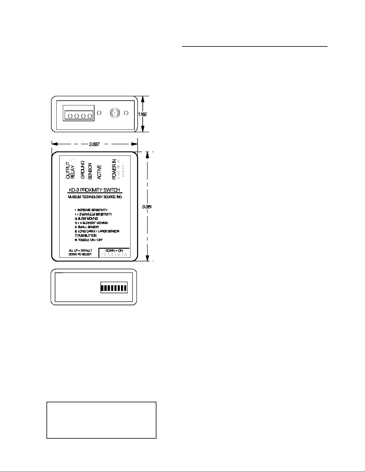
KD-3 Proximity Switch
*Turns objects into touch activated switches
*Activates from inches away
*Works through wood, plastic
*Easy setup...self calibrating
*Normally open relay output
*Operates on 9 to 24 Volts DC
*Wide range of sensor sizes
*Output mode: pushbutton, toggle or timed
PRELIMINARY INFORMATION
June 2012
The KD-3 is a capacitive proximity switch that uses a combination
of analog and digital techniques to detect a change of capacitance on a remote sensing plate. The capacitance change is
brought about when the sensing plate is approached or touched.
Upon activation, a normally open relay closes, indicated by a red
LED lighting. Three modes are available: Pushbutton, in which
the relay stays closed for as long as presence is sensed; Pulse,
in which the relay closes for one second and then opens, or
Toggle, where the relay closes on the first touch, remaining
closed until a second touch occurs.
The KD-3 can work with sensing plates of various sizes and
shapes. The sensing plate needs to be of metal, such as copper
or aluminum, although others will also work.. In certain cases the
artifact itself may be used as the sensor, as in the case of a metal
teapot or bowl. In other cases, the sensor may be embedded in
the object, provided that the object is non-metallic. The KD-3 is
normally mounted close to the sensor, with a single wire connecting the two. By use of coaxial cable, this distance may be
extended to several feet.
The sensor size and shape will, to some extent, determine the
distance over which the KD-3 will activate. Although not always
required, internal adjustments are available to optomize the sensitivity and hence operating range. The KD-3 has been tested
with sensor plates as small as one-half inch square, and as large
as 12 by 16 inches.
The Auto-Calibration feature adjusts the KD-3 continuously to the
environment. Such things as dirt, humidity, ice or damage to the
sensor plate are automatically accounted for.
Museum Technology Source Inc.
323 Andover Street Wilmington MA 01887
800-729-6873 | 978-657-3898
fax 978-657-7132
www.museumtech.com
Rev B June 2012
Page 2
Museum Technology Source Inc.
PRELIMINARY INFORMATION--SUBJECT TO CHANGE
June 2012
Museum Technology Source Inc.
323 Andover Street Wilmington MA 01887
800-729-6873 | 978-657-3898
fax 978-657-7132
www.museumtech.com
Preliminary Specifications
Principle of Operation: Change in electrical capacitance
Sensing range: Depending upon sensor size and shape up to
10 inches (250 mm)
Response time: Typically 0.1 second or less
Calibration: Automatically calibrates to installed environment
Input-Output: 4 position 5.08 mm pluggable terminal
Output: Normall open relay, 24 Volt, 1 Amp rating
Power: 9 to 24 Volts DC, 10 mAstandby, 70 mA active
2.1 mm jack
Power Input reverse polarity protected
Protection: Passes JESD22-A114 Electrostatic Discharge
Sensitivity Testing, Human Body Model (HMB)
+ / - 2000 Volts
Passes JESD22-A115 Electrostatic Discharge
Sensitivity Testing, Machine Model (MM)
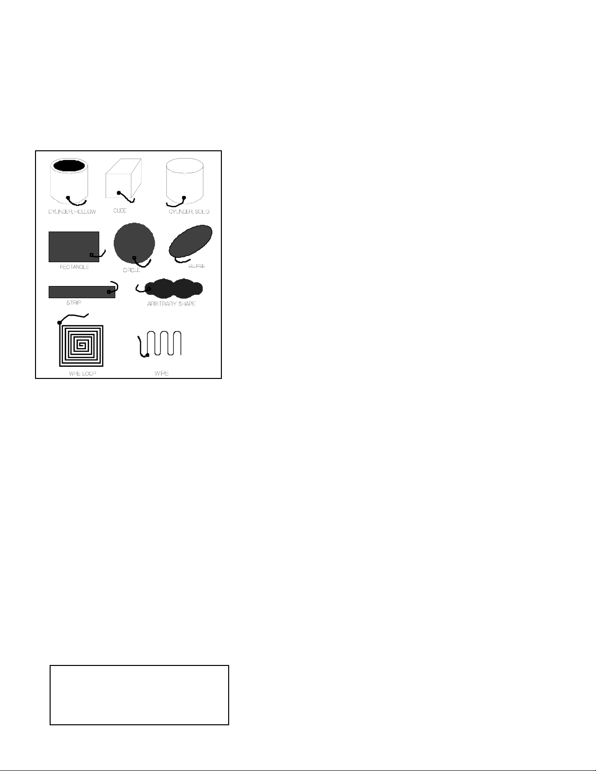
Possible Sensor Shapes
KD-3 Proximity Switch
Principle of Operation
The KD-3 operates on the basis of detecting a change in the electrical capacitance between the sensor plate and the triggering object, which is usually the human hand. The capacitance of the sensor plate is constantly being compared to an internal
reference. When the capacitance increases as a hand approaches, a threshold, set by the internal reference, is exceeded
and the output switches on.
The internal reference automatically adjusts to take into account changes in humidity, or dirt on the sensor. This helps
ensure long-term reliability.
The sensor plate may take almost any shape or form, and may be placed behind plastic, glass or other matertial that does
not conduct electricity. The sensor may be molded into an object, thus when the object is touched the output activates.
The sensor plate should connect to the KD-3 with as short a wire as possible. In general, a lead wire of twelve inches or less
works fine. For greater distances, coaxial cable should be used for distances up to several feet.
The KD-3 is to some degree sensitive to the speed of the hand as it approaces the sensor. Extremely show movement may
result in the hand not being detected. However, experience shows that the user intuitively and quickly adapts to the behavior
of the KD-3
Page 3
INSTALLATION
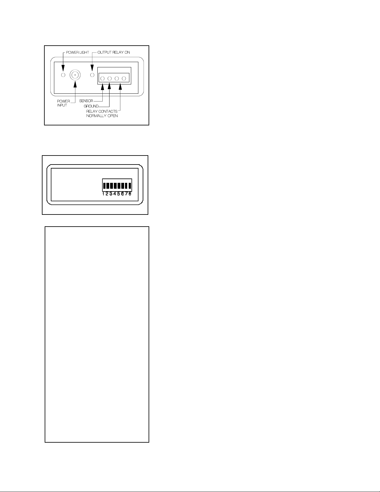
Connect the SENSOR screw terminal to the sensing plate or wire
to be used. The wire connecting the two should be kept as short
as possible to maintain sensitivity. The maximum length of the connecting wire is largely determined by the size of the sensor. A large
sensing plate will allow for a longer connecting wire. If a small
sensing plate is to be used with the KD-3 mounted at a distance,
coaxial cable should be used, with the shield connected to the
GROUND terminal
Connect the supplied 9 Volt DC power supply to the POWER IN
jack. Allow ten seconds or so for the KD-3 to complete its calibration cycle and then move a hand towards the sensor. When the
hand is detected, the normally open relays contacts will close, and
the red ACTIVE light will illuminate.
SETTING OPTIONS
It is well to bear in mind that each installation is to some degree dif-
ferent. Hence it is recommended that various settings be tried until
optimal operation is achieved. Please consider these instructions
to be a general outline of the KD-3’s operation, and not a set of
absolute requirements.
As supplied, all switches are in the up position. This sets the KD-3
to the default settings, which are appropriate for most applications.
The optional settings configure the KD-3 to deal with the installation
at hand. After making a new setting, briefly power off the KD-3.
Switches 1 and 2 serve to increase the sensitivity. With both in the
down position, maximum sensitivity is provided. Do not use more
sensitivity than actually required to avoid false triggering.
In situations where the hand approaches the sensor a a slow rate,
placing switch 3 in the down position will make the KD-3 more
responsive. Switch 4 provides for even slower movement, and 3
and 4 both down is for very slow motion. Be aware that using
these settings will make the KD-3 less sensitive to a fast moving
hand.
If a small sensing area is used, in the order of a few square inches,
switch 5 should be placed in the down position.
If a long wire is used to connect the sensing plate to the KD-3, or if
a large sensing plate is used, switch 6 may be helpful in maintaining sensitivity.
With both switches 7 and 8 in the up (off) position, the relay will
close for approximatey 1 second and then open when a hand is
detected. Placing switch 7 down activates the pushbutton mode, in
which the relay remains on as long as the hand is within the detection range. With switch 8 down, the KD-3 is in toggle mode. The
first detection will turn the output on, and it will remain on until a
second detection occurs.
DIP SWITCH FUNCTIONS
Default is all UP
1. Increase sensitivity
2. Additional sensitivity
1 + 2. Maximum sensitivity
3. Slow moving
4. Slower moving
3+4. Slowest moving
5. Small sensor area
6. Long cable and or large sensor
7. Pushbutton mode
8. Toggle mode
Revised 11-1-2012
 Loading...