

Page 1
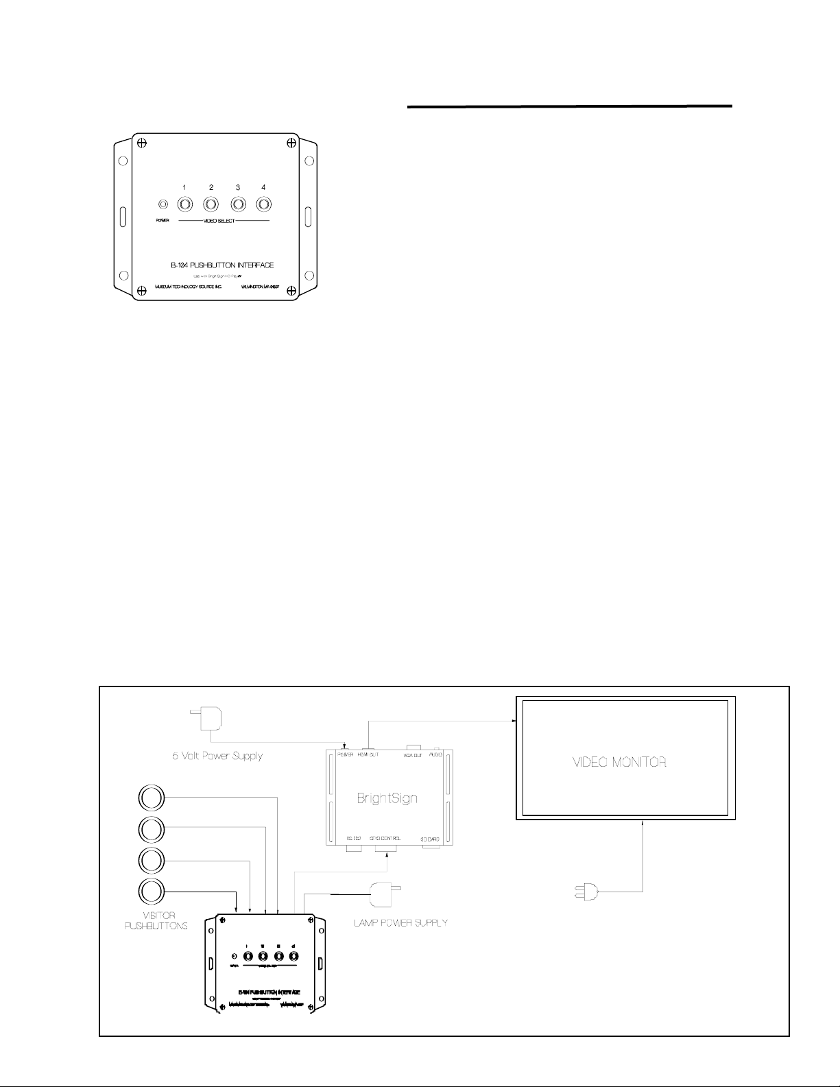
B-104 Pushbutton Interface
Used with BrightSign video players
Pushbutton selection of four videos
Pushbutton Illumination
These instructions also apply to the B-101 Single Button Interface. Disregard Buttons 2,3&4.
The B-104 provides a convenient method of connecting pushbuttons to BrightSign HD410, HD810 or
HD1010 video players. Connection is to the GPIO (General Purpose Input Output). Four of the eight
lines are used as inputs, and the remaining four are used as outputs to illuminate the pushbutton light
while the selection is playing.
Four RJ-11 connectors are provided for connection to external pushbuttons.
An external wall-mount power supply provides power for pushbutton lamps, or for other activators, such
as motion detectors. The B-104 will operate fully without the power supply, but the lamps will not illuminate. If non-illuminated pushbuttons are used, the power supply is not required.
Installation:
The B-104 should be connected as show in the drawing below.
The pushbuttons on the B-104 duplicate the function of the remote visitor pushbuttons. These buttons
are useful for test and setup purposes, but are not intended for use by the public.
It is suggested to test the installation using the video files supplied either on an SD Memory card or on
CD to verify that the equipment is working properly prior to loading the actual video files to be used.
Museum Technology Source Inc.
p1
B-101 Single Button Interface
Page 2
Preparing the Content
A sample program is included on a CD. This program was generated using the BrightAuthor program, a copy of
which is also on the CD. The latest version of BrightAuthor may be obtained at no charge from
www.brightsign.biz Full documentation on using BrightAuthor is available at the same website.
Please refer to the Appendix for a discussion on file types and video quality.
Although any grade of SD memory card is likely to work, the safest choice is a high speed Class 10 card.
BrightAuthor requires the player to be running Firmware version 3.7.44 or higher. The latest version may be
downloaded from www.brightsign.biz The version number is displayed on the video monitor while the player is
powering up.
After the BrightAuthor program is installed, copy the file Four Button from the supplied CD. Now copy the
videos to be played into the same folder. Open the folder and click on the Four Button.bpf icon. This should
launch the BrightAuthor program which consists of five video files: Attract.mpg, video1.mpg,video2.mpg,
video3.mpg, and video4.mpg. These are the files that need to be replaced with the actual files to be used.
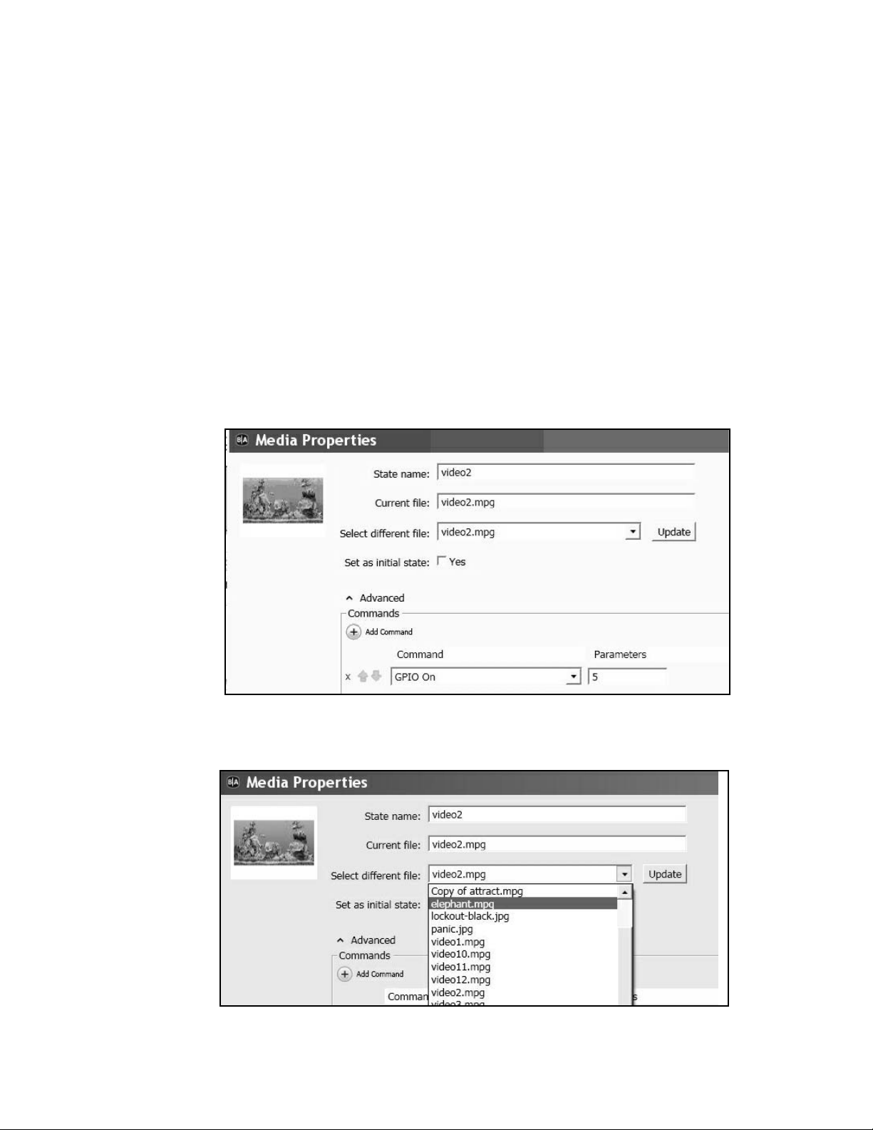
To update the file, double-click on the icon of the file to be changed. In the example below, video2.mpg
has been selected causing the MEDIA PROPERTIES dialog box to open.
Now use the Select different file pull-down menu to select the desired new video. In this case,
video2.mpg will be changed to elephant.mpg Be sure to click the Update box, otherwise the
change will not go into effect.
The same technique is used to change the other videos as required. When finished, save the file and
use the PUBLISH tab to publish the presentation to the SD memory card.
p2
Page 3
INPUT - OUTPUT SETTINGS
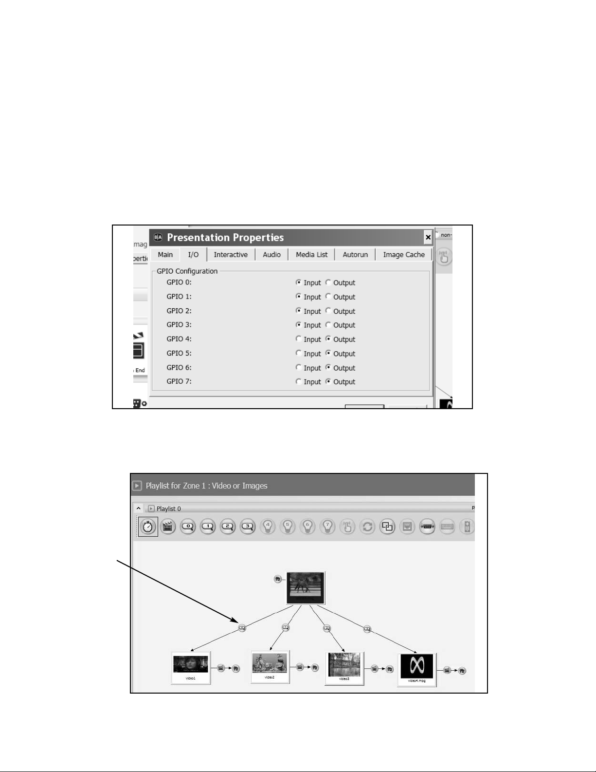
The supplied program will turn on the button lamp while the video associated with that button is playing, turning off at the end of the video. To accomplish this, GPIO 0, 1, 2, and 3 are defined as INPUTS, while GPIO
4, 5, 6, and 7 are defined as OUTPUTS. If for any reason it is necessary to change these, it may be done
under FILE > PRESENTATION PROPERTIES > I/O as illustrated below.
To set the action of the pushbuttons click on the GPIO EVENT icon (see below).
GPIO Event
p3
Page 4
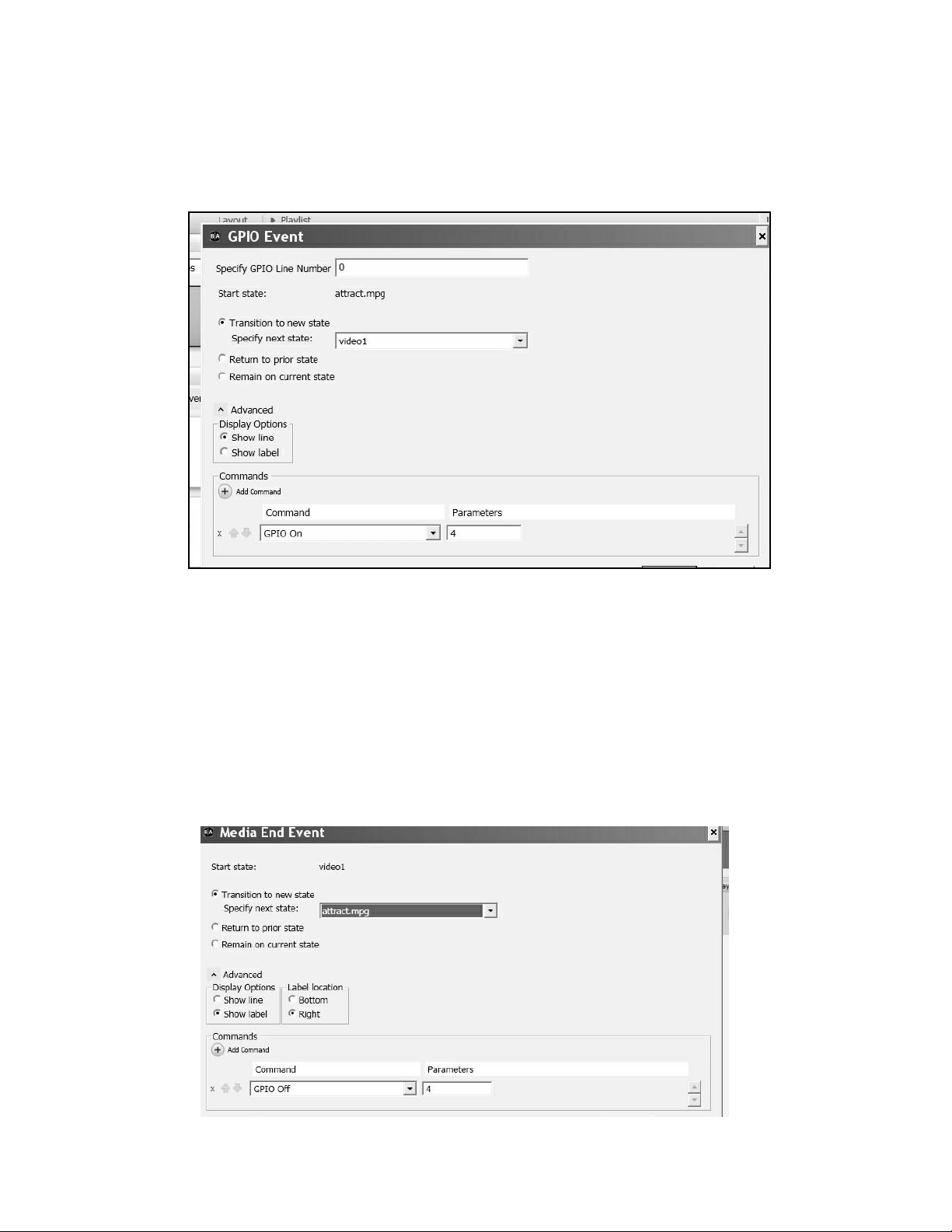
This will cause the GPIO EVENT dialog box to open. SPECIFY GPIO LINE NUMBER is where
the pushbutton number is entered as follows:
Button 1 = GPIO 0
Button 2 = GPIO 1
Button 3 = GPIO 2
Button 4 = GPIO 3
To turn on the pushbutton lamp, the ADD COMMAND function is employed. To turn on an output,
select GPIO On from the pull-down menu, and enter the output number in the Parameters box
using the following assignments:
Button Lamp 1 = 4
Button Lamp 2 = 5
Button Lamp 3 = 6
Button Lamp 4 = 7
To turn off the button lamp, double click on the MEDIA END icon which appears with each of the
video icons on the edit screen. The following dialog box will appear:
Using ADD Command, select GPIO Off and enter the output number using the same Button Lamp
assignments as were used to turn the output on.
p4
Page 5
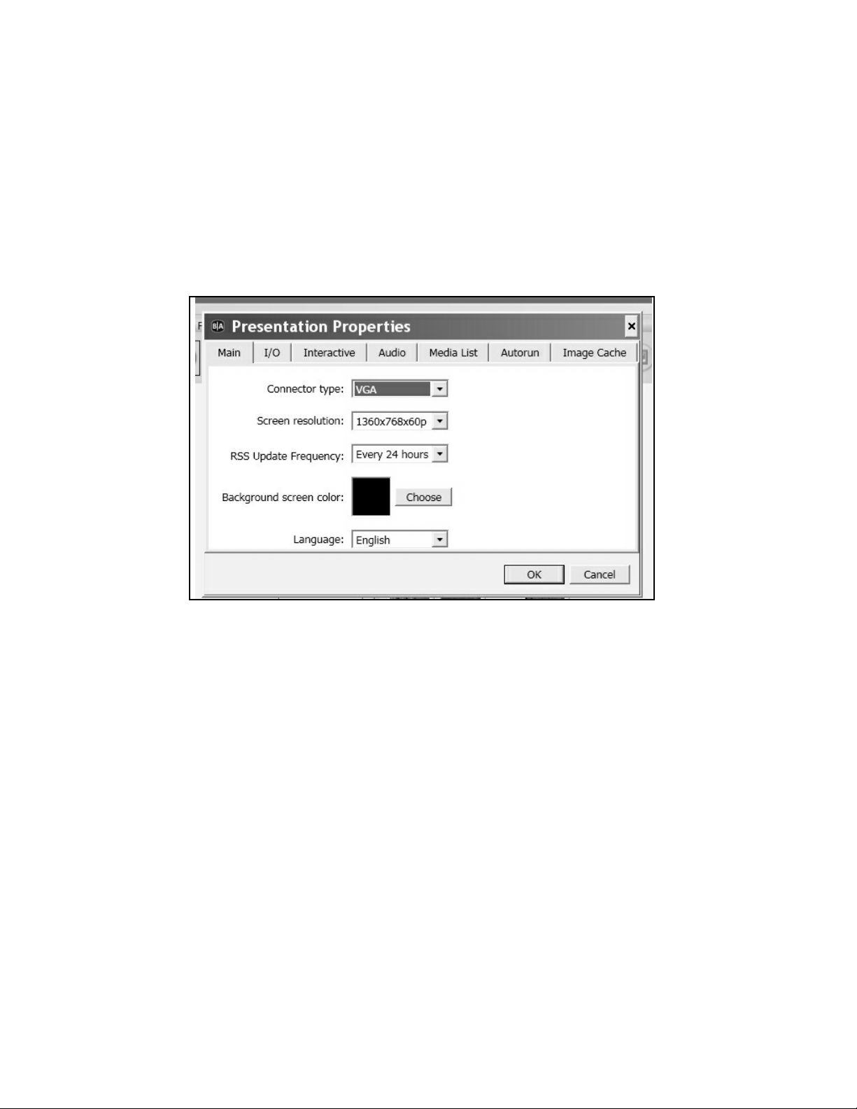
Presentation Properties:
Under the main FILE menu, select Presentation Properties.
The Connector Type pull down is used to select the type of connector that is being used with the monitor.
The choices are VGA, which is the 15 pin connector commonly used on personal computers. The other
option is HDMI, which is standard on flat-screen video monitors. An advantage of HDMI is the same cable
that carries the picture also carries the sound, whereas VGA will require a seperate patch cord from the
BrightSign to the monitor, provided the monitor has built-in sound. Otherwise amplified speakers will be
required.
It is suggested that Screen resolution be set to match the available resolution of the monitor being used.
RSS Update Frequency does not apply in this application, so the default 24 hour setting need not be
changed.
Background Screen Color sets the color of the default background. Normally, the images will fill the
screen, so this color will not be seen. However, if the image doesn’t fill the entire screen, the background
color will fill in around it. Generally black is a good choice.
Publishing
When finished editing the presentation, the next step is to publish it to the SD Flash Memory Card to be
used in the player. Although almost any SD card will work, a Class 10 card is recommended because of
its high speed characteristic. Of course the card must have sufficient capacity to store the video content.
Simply add together the size of the individual videos to arrive at the required size. Acard of larger than
required capacity may be used.
Use the file menu to Save the presentation, then click the Publish button. When the process finishes,
the card may be plugged into the BrightSign player. Make sure that the player is disconnected from its
power supply. After inserting the card, reconnect power to the BrightSign. Allow 2 to 3 minutes for the
player to boot.
p5
Page 6
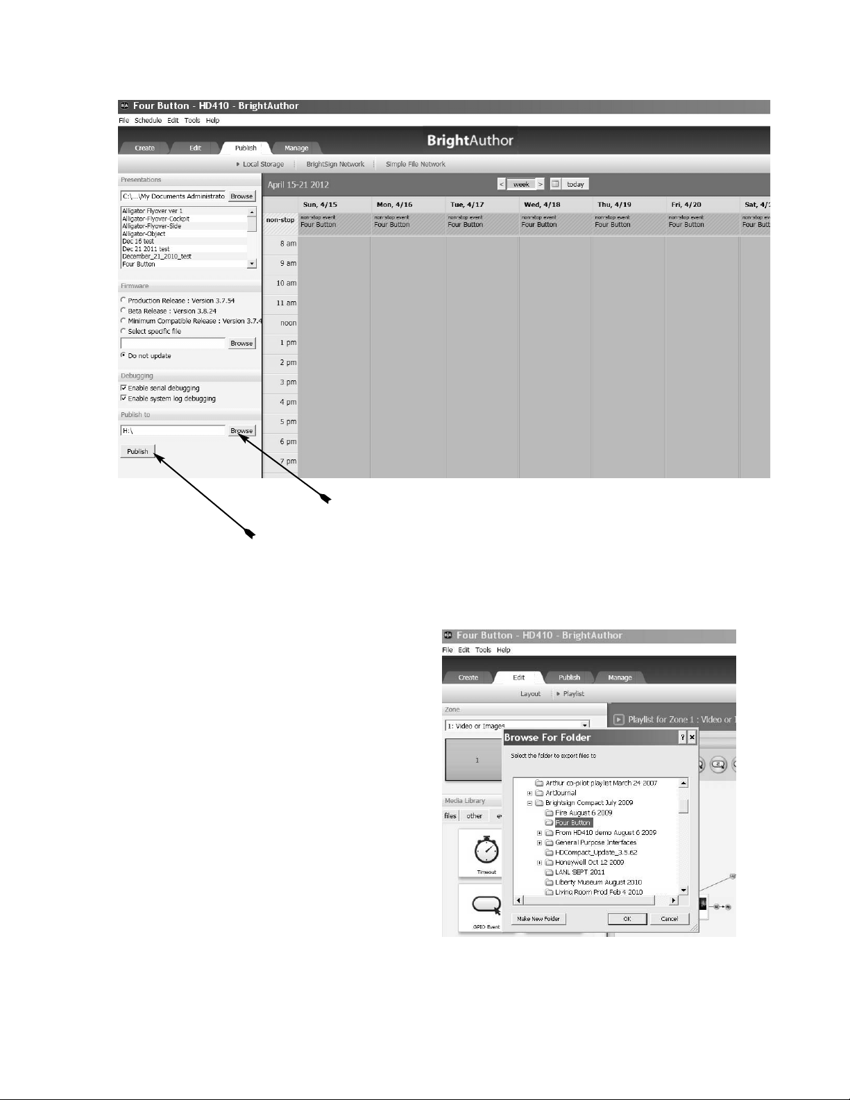
Select the location of the SD Memory Card
Publishing Screen
Click here to save presentation to SD Memory Card
Exporting the Presentation
There is a difference between Publishing and
Exporting a presentation. The Publishing
process manipulates and merges the files into a
form readable by the BrightSign player. It is not
possible to later edit a published presentation.
Exporting a presentation keeps the files seperate, so they may be loaded into BrightAuthor
using the File Open Presentation command. The exported files may then be editing
on any computer running BrightAuthor.
To export a presentation select Export from
the File menu, then browse to locate the folder
in which the presentation is to be saved.
Export screen
p6
Page 7
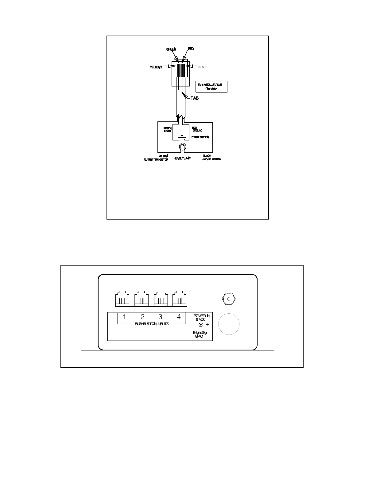
250 MA MAX
START PUSHBUTTON WIRING STANDARD
YE LLO W: Col lect or of NPN transistor conducts
to g r oun d to tur n on lamp
GREE N: Connect t o ground to start. Source is
12 VD C at 10 mA
RED: Comm on ground
BLAC K: Sou rc e of 1 2 VDC to po w er lamp.
Maxim um l oad 250 m A
Pushbutton Wiring
Rear panel showing connectors
Museum Technology Source Inc.
323 Andover Street Wilmington MA 01887
800-729-6873 | 978-657-3898 | f 978-657-7132
www.museumtech.com
March 2012 Rev A
p7
 Loading...