

Page 1
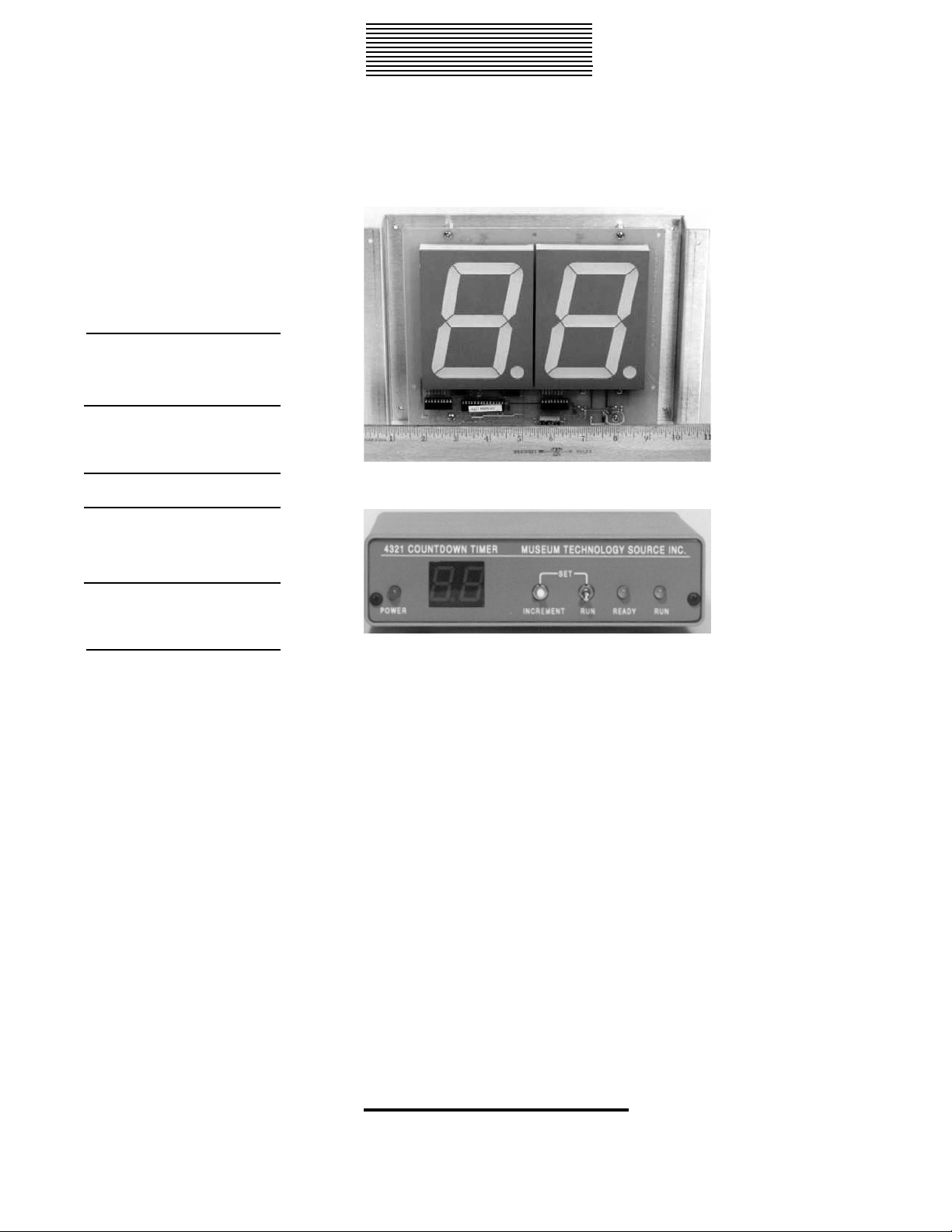
2 Component
System with Display
and Control
4321 Count Down Timer
For presentations that start on a regular cycle, the 4321 provides an easy
method to automatically start the show, as well as to indicate to the waiting public how long it will be before the next show starts.
The 4321 consists of two components: the control unit, and the display.
The control unit may be installed where most convenient, usually next to
the equipment to be started, while the display, with its two 4 inch high
digits, may be be mounted for optimal visibility to the public.
In operation, the control unit is preset with the desired intermission time.
When placed in run mode, the remote display will display the preset
time, and proceed to count down, in one minute increments, to zero.
When zero is reached, a relay in the control unit closes for one second.
This contact is used to activate show control equipment, such as DVD or
audio control units.
For venues with multiple entrances, multiple displays may be employed.
The display units are merely connected in parallel. The RS-485 data
transmission technique used, allows the displays to be hundreds of feet
apart if required.
Several modes of operation are available, set by DIP switches on the rear
panel.
Can be mounted in
any custom exhibit
Easily Adaptable
Switches provide
several modes of
operation
Additional displays
can be used for multiple entrances
323 Andover Street Wilmington, MA, 01887
800-729-6873 / 978-657-3898 Fax: 978-657-7132
www.museumtech.com / [email protected]
Starts show and
notifies public when
the next show will
start
Revised 1/03
Museum Technology Source, Inc.
Display section with 4 inch digits
Control Unit
Page 2
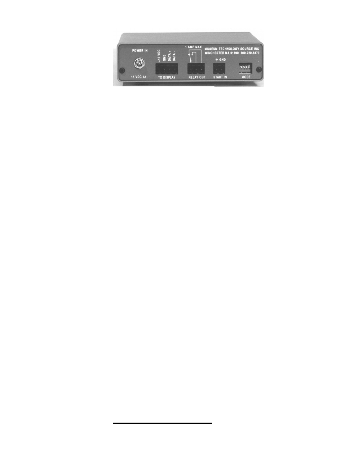
4321 Count Down Timer
Technical Specifications
Display
Time Range
Operating Modes
Start Input
Relay Output
Display Connection
Power
Controls
Display Physical
Control Physical
Included Accessories
Optional Accessories
Two digit, 4 inch high LED. Red standard; green available
1 to 99 minutes in 1 minute increments
a) counts down continuously; upon reaching zero reverts to
present number and starts counting down again. b) counts
down as long as contact is maintained across start terminals.
c)Starts counting upon momentary contact across start terminals.
d) same as (c) but if momentary contact while counting will
cause display to revert to preset count
Optoisolated input. Start switch must be capable of switching
12 VDC @20mA. Screw terminals on plugable block
SPDT relay rated at 2 Amps, 24 VDC. Activates for 1 second.
three screw terminals on plugable block
4 wires; 2 for RS-485 data; 2 for 12 VDC power @ 700mA
Supplied 15 VDC 900 mA external power supply. Sufficient for
control unit and one display; multiple displays require additional power
Front panel Run/ Set toggle. In Set mode, Increment pushbutton is held until desired time is indicated on 2 digit display control unit. Toggle in Run position enables normal operation.
Front panel display reads same as remote display. Two LED’s
indicate status
Display is mounted on 9.4”x7.1” metal plate which is attached to
13.5” x 9.5” red Plexiglas drilled with 4 countersunk holes for
mounting to exhibit surface. Weight 3 lbs.
1.5” high x 5.5” wide x 9.0” deep. Weight 3 lbs.
Power supply, 20 foot 4 conductor interconnect cable
RK-3 Rack Mount Kit; additional display units.
Rear Panel View of Control Unit
323 Andover Street Wilmington, MA, 01887
800-729-6873 / 978-657-3898 Fax: 978-657-7132
www.museumtech.com / [email protected]
Page 3
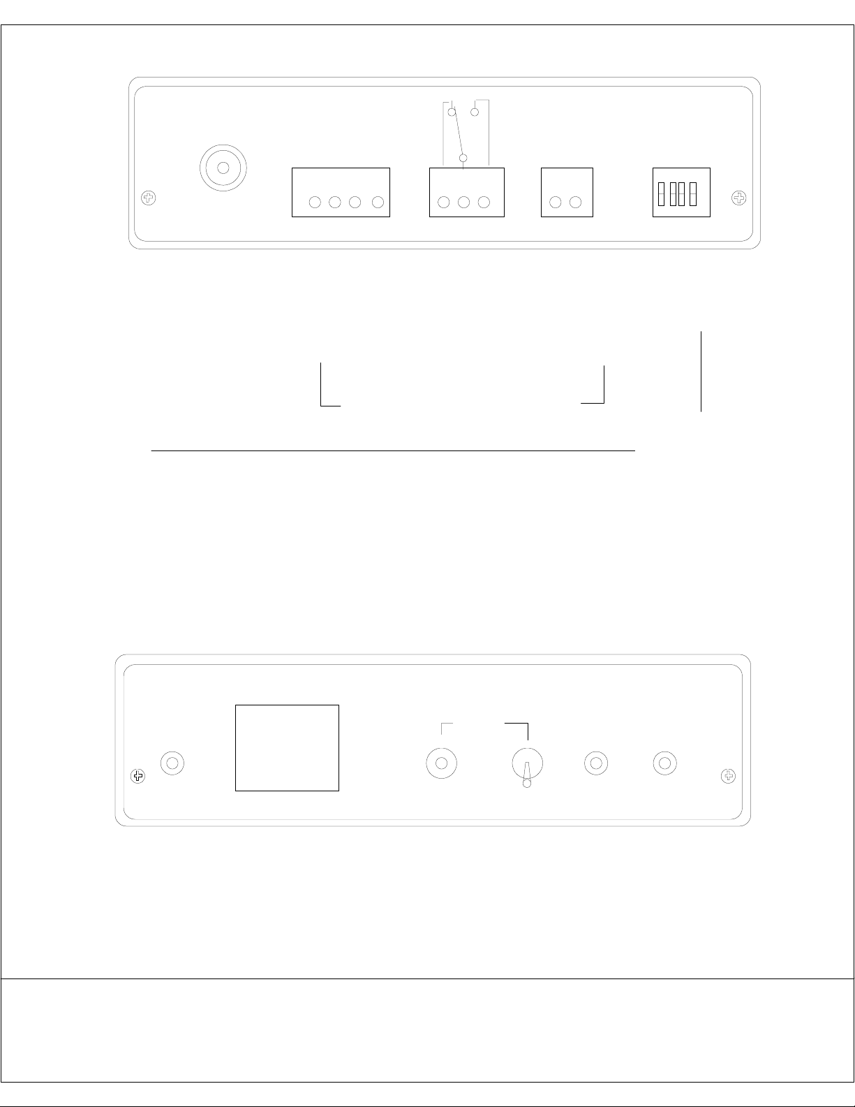
REAR PANEL, 4321 COUNTDOWN TIMER
POWER IN
GND 4 3 2 1
+
START
15 vdc
DATA +
+12 VDC
DATA -
GROUND
TO DISPLAY
RELAY OUT
DISPLAY DRAWS 600 MA MAX
DATA IS RS-485
DIP SWITCH MODE SETTINGS 0 = DOWN 1 = UP
0 0 0 0 COUNT STARTS WITH MOMENTARY CONTACT ACROSS START TERMINALS.
ADDITIONAL START CONTACTS IGNORED.
0 0 1 1 SAME AS ABOVE EXCEPT ADDITIONAL START COMMAND WHILE COUNTING
WILL CAUSE DISPALY TO REVERT TO PRESET NUMBER
0 0 0 1 DISPLAY COUNTS DOWN CONTINUOUSLY
0 0 1 0 DISPLAY COUNTS DOWN AS LONG AS CONTACT
IS MAINTAINED ACROSS START TERMINALS
ALL MODES: RELAY OUTPUT PULSES AT ZERO
TO DISPLAY:
1 +12 VDC
2 GROUND
3 DATA +
4 DATA -
PLUGGABLE TERMINAL BLOCKS
RELAY OUT
NORM OPEN AND
NORM CLOSED
CONTACTS
TO START EXTERNAL
DEVICE AT END OF
COUNT
START TERMS
MOMENTARY
CONTACT STARTS
COUNTDOWN
DIP SWITCHES TO
SELECT VARIOUS
OPERATING
MODES
MUSEUM TECHNOLOGY SOURCE MOVEL 4321 TIMER
POWER
4
1
POWER ON
LAMP
DISPLAY DUPLICATES
REMOTE READOUT
IN "SET" MODE USE
TO INCREMENT TO
DESIRED TIME
FRONT PANEL, 4321 COUNT DOWN TIMER
FRONT AND REAR VIEWS
4321 COUNT DOWN TIMER
SET
INCREMENT
UP TO SET
TIME, DOWN
FOR NORMAL
OPERATION
MAY 20 1999
Revised July 9 2001
RUN READY
LIGHTS
WHEN
READY
RUN
FLASHES
WHILE
COUNTING
MUSEUM TECHNOLOGY SOURCE INC
323 Andover St Wilmington MA 01887
800-729-6873 fax 978-657-7132
www.museumtech.com
Page 4
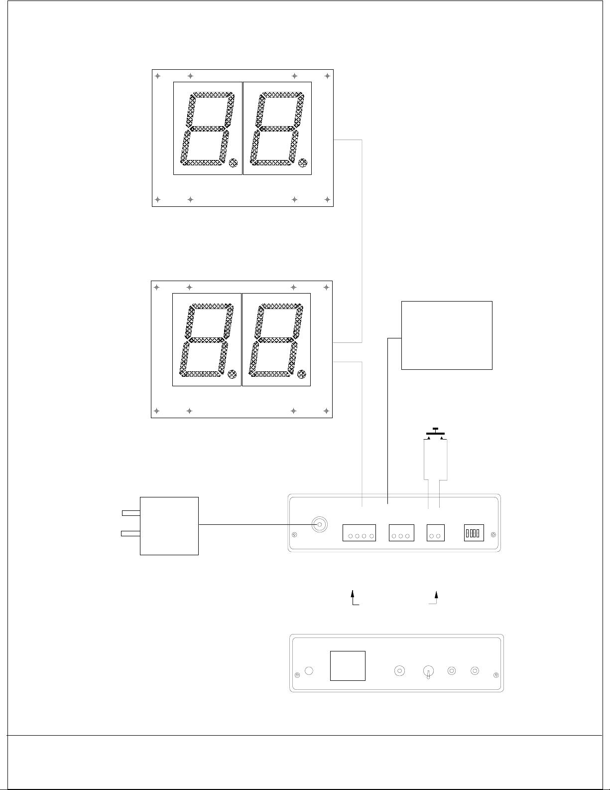
OPTIONAL SECOND DISPLAY
A
A
A
A
A
A
A
A
DISPLAY
A
A
A
A
AA
AA
A
A
AA
AA
Note: If distance between Control Box and Display
causes excessive voltage drop, a local power
supply for the display may be used. The Control Unit
provides 15 VDC, and the Display requires at least 12 VDC,
allowing for a 3 volt drop in wiring.
The local power supply should provide at between 12 and 17 VDC
at 500 mA.
A
A
DEVICE TO BE
STARTED
(VIDEO, AUDIO ETC)
A
A
A
A
POWER SUPPLY
15 VDC @900 mA
REAR PANEL
FRONT PANEL
A
A
A
A
2 PAIR CABLE
POWER AND DATA
POWER IN
12 VDC
MUSEUM TECHNOLOGY SOURCE MOVEL 4321 TIMER
POWER
TO DISPLAY RELAY OUT
1 2 3 4
TO DISPLAY:
1 +12 VDC
2 GROUND
3 DATA +
4 DATA -
1
4
START SWITCH
UP
START
1 2
START TERMS
MOMENTARY
CONTACT STARTS
COUNTDOWN
SET
RUN
1 2 3
RELAY OUT
NORM OPEN AND
NORM CLOSED
CONTACTS
TO START EXTERNAL
DEVICE AT END OF
COUNT
PLUGGABLE TERMINAL BLOCKS
READY
DIP SWITCHES TO
SELECT VARIOUS
OPERATING
MODES
RUN
4321 TYPICAL INSTALLATION
Revised July 9 2001
4321_install.fcw
Museum Technology Source Inc.
323 Andover St Wilmington MA 01887
800-729-6873 fax 978-657-7132
www.museumtech.com
Page 5
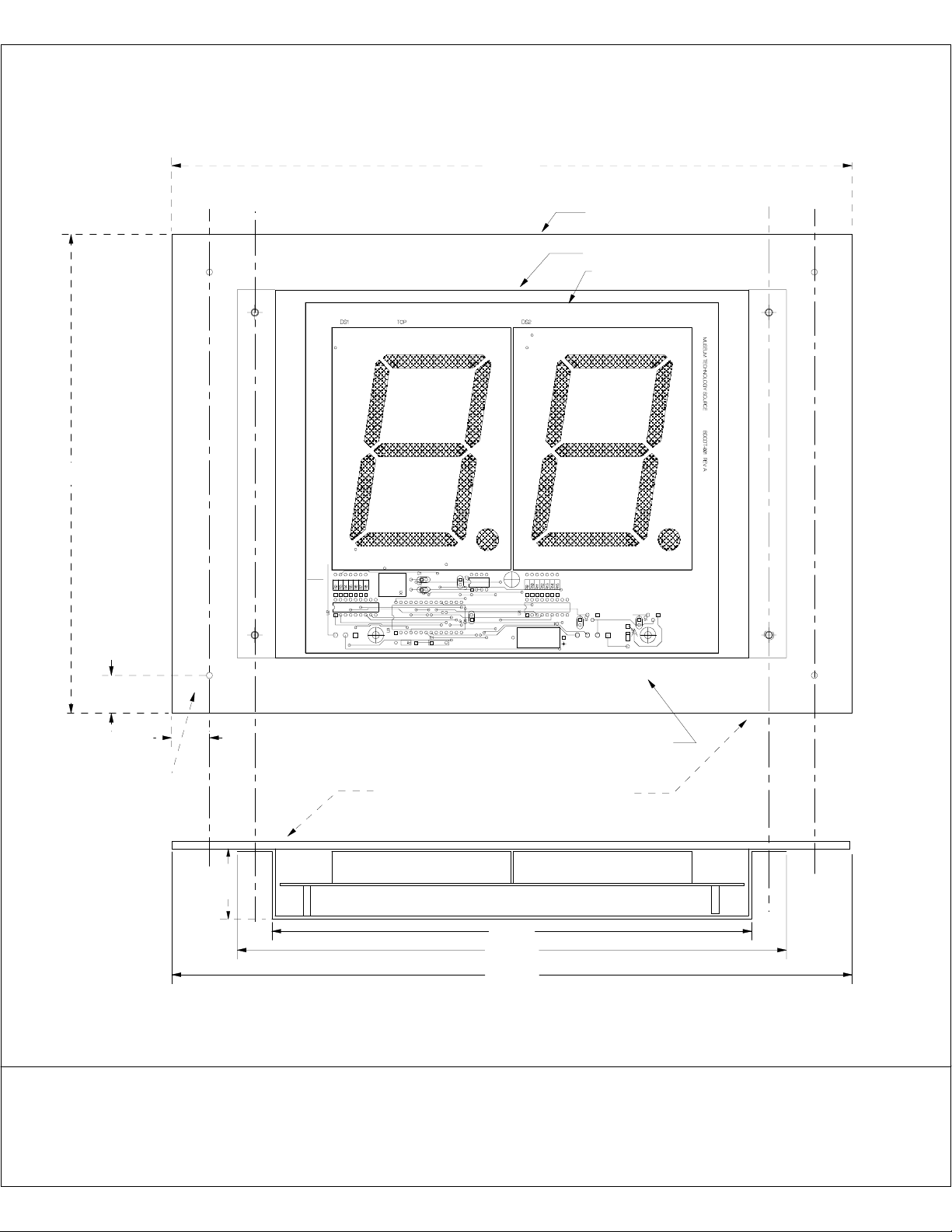
13.500
Note: Circuit Board is not visable through red Plexiglas
Only illuminated digits show
Red Plexi Mounting Plate
9.500
0.750
A A
BB
B
A
Metal Sub Plate
Circuit Board
B
A
Connector to
Control Unit
Mounting Holes
4 Places Drilled
0.750
Front View
Mounting Plate, 1/8" Red Plexiglas
for # 8 Screw
1.400
9.525
10.900
13.500
View from Top
4321 Count Down Timer
Display Mounting Dimensions
Museum Technology Source Inc.
Wilmington Mass. 01887
800-729-6873
Revised October 2003 MPC
Page 6
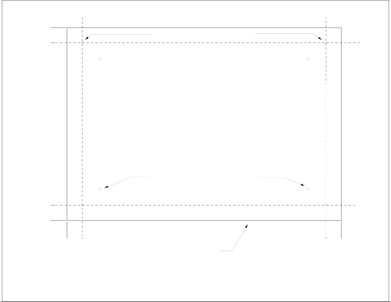
9.500
8.750
Mounting Holes for # 8 Screw, 4 places
For Attaching Display to Surface.
#6 Flathead screws attach display to Plexi
0.750
0.000
0.000
0.750
1/8 " Red Plexiglas
4321 Countdown Timer Display Mounting Dimensions
12.750
Dec 5 2002 MPC
Museum Technology Source Inc.
13.500
 Loading...