

Page 1

Copyright 2004-2005 Muse Research, Inc. All Rights Reserved.
Receptor v1.2
User’s Guide
Muse Research, Inc.
970 O’Brien Drive
Menlo Park, CA 94025
USA
Tech Support: (650) 326-6180
Main Office: (650) 326-5400
March 31, 2005
Muse Research, Receptor, MuseMachine, and the Muse Research logo are trademarks of Muse Research, Inc.
VST is a registered trademark of Steinberg Media, GmbH. ADAT and the ADAT logo are registered trademarks
of Alesis, LLC and are used here under license. Macintosh and the Apple logo are registered trademarks of
Apple Computer, Inc. Windows and the Windows logo are registered trademarks of Microsoft Corporation.
All other trademarks used herein are property of their respective holders. No portion of this manual may be
reproduced or distributed without the express written consent of Muse Research, Inc.
1 Receptor Manual
Page 2

--------------- Warning ---------------
To prevent fire or shock do not expose this appliance to rain or moisture. Refer servicing to qualified service
personnel.
Notice Regarding Electromagnetic Emissions
This device complies with part 15, subpart J of FCC rules. Operation is subject to the following two conditions:
(1) this device may not cause harmful interference, (2) this device must accept any interference that may cause
undesired operation. Changes or modifications to this device not expressly approved by the manufacturer may
void your authority to operate it. When connecting this product to accessories and/or other equipment use only
high quality shielded cables.
Notice Regarding GPL License conditions
This product is based on the Linux Operating system, some or all of which may be administered under terms of
the GNU General Public License (GPL) agreement as published by the Free Software Foundation.
Software distributed under the terms of the GNU GPL may be redistributed or modified under the terms of
the GNU GPL, either version 2 of the License, or any later version. Programs distributed under the GNU GPL
are done so WITHOUT ANY WARRANTY; without even the implied warranty of MERCHANTABILITY or
FITNESS FOR A PARTICULAR PURPOSE. See the GNU General Public License for more details.
A copy of the GNU GPL agreement is available from the Muse Research website (www.museresearch.com) as
well as on the Receptor CD.
A machine-readable copy of the GPL compliant software in this product is available from Muse Research for a
small fee to cover costs of producing and mailing the CD by writing to:
Muse Research, Inc.
970 O Brien Drive
Menlo Park, CA. 94025
IMPORTANT SAFETY, INSTALLATION & USE INSTRUCTIONS
INSTRUCTIONS PERTAINING TO THE RISK OF FIRE, ELECTRIC SHOCK, OR INJURY TO
PERSONS
WARNING: READ THIS FIRST!
When using electric products, basic precautions should always be followed, especially the following:
1 Read and follow the Safety, Installation, and Use instructions before using this product.
2 This product must be grounded. If it should malfunction or break down, grounding provides a path of least
resistance for electric current to reduce the risk of electric shock. This product comes with a power supply
cord with integral equipment grounding conductor and grounding plug. This power supply cord must be
plugged into an appropriate outlet which is has been properly installed and grounded in accordance with
local electrical building codes and ordinances. Use in countries other than the North America may require
the use of a different power cable or attachment plug, or both.
DANGER
Risk of electrical shock or fire exists if the grounding scheme of a product is defeated or modified so that the
ground is improperly connected. Do not modify the plug on the power supply cord provided with this product
— if the power plug does not plug into your existing outlet, or you are in doubt as to whether the product is
properly grounded, check with a qualified electrician.
2 Receptor Manual
Page 3

CAUTION
If Receptor is rack mounted, a standard 19-inch open frame rack must be used. Do not install Receptor in rack
that does not allow or provide for free air movement in and around the device or overheating and possible
product damage may result.
3 To reduce the risk of injury, do not allow children to operate any electrical product without close
supervision.
4 Do not use Receptor near water -- for example near a bathtub or shower, next to a sink, in a damp
basement, or near or in a swimming pool or wet location.
5 Receptor MUST be installed so that its location or mounting position does not interfere with its proper
ventilation on the sides, bottom and rear of the unit. Do not modify or obstruct any of the fans in this
product or overheating will result, possibly causing permanent damage.
6 Receptor should be located away from heat sources such as radiators, heat registers, fireplaces, stoves, or
ovens, or on top of or in between amps or other heat generating devices.
7 Receptor should only be connected to a power supply of the type described in the instructions and marked
on the product using the proper power supply cable.
8 This product, in combination with an amplifier, headphones, and/or speakers, may be capable of producing
sound levels that could cause full or partial hearing loss and/or damage other audio equipment such as
speakers. Take all necessary precautions to protect your hearing when using this or any other audio device
by ensuring that the maximum output volume of your monitoring system is kept to a safe level well below
the threshold of damage.
9 Receptor may be equipped with a polarized line plug (where one blade is wider than the other) which
ensures it can only be inserted into a polarized outlet. This is a safety feature that prevents line and neutral
from being inadvertently reversed. If you are unable to insert this plug into the outlet, do not modify the
plug. Contact an electrician to install the appropriate power outlet.
10 The power supply cord should be removed from the power outlet when not being used for extended
periods of time.
11 Care should be taken so that foreign objects or liquids are not introduced into the product enclosure
openings.
12 The product should be serviced by a qualified service person when any of the following events occur:
A. The power supply cord or the plug have been damaged;
B. Objects have fallen into or liquid has been spill into the product;
C. The product has been exposed to rain;
D. The product does not appear to be operating normally or exhibits a marked change in performance;
E. The product has been dropped or the enclosure has been damaged.
13 Do not attempt to service this product beyond what is described in the user maintenance instructions. Any
required service should be performed by qualified service personnel. Please contact the factory for your
nearest qualified service center.
14 For your personal safety and the safety of others:
A. Do not operate this or any other audio device for long periods of time at high volume levels or at a level that is
uncomfortable. Ensure your hearing is protected against inadvertent, excessive sound pressure level in your studio
or performance environment. If you experience any hearing loss or ringing of the ears consult your physician or
audiologist.
B. Take care when programming any of the synth filters, distortion programs, or filter effects contained herein using
extreme operating parameters. These actions could also produce signals which result in potentially damaging sound
levels as noted previously.
3 Receptor Manual
Page 4

WARNING
Do not place objects on the product s power supply cord, or place the product in a position where anyone could
trip over, walk on, or roll anything over cords of any type. Do not allow the product to rest on or be installed
over cords of any type. installations of this type create the possibility of a fire hazard and/or personal injury.
MAINTENANCE INSTRUCTIONS
1 This product should be kept clean and dust free. Periodically wipe the unit with a clean, lint free cloth. Do
not use solvents or cleansers as they may damage or scratch the finish.
2 There are no user lubrication, adjustment, or alignment requirements for this product.
3 Refer all other servicing to qualified service personnel.
--------------- SAVE THESE INSTRUCTIONS ---------------
4 Receptor Manual
Page 5

----- End User Software License Agreement -----
SOFTWARE LICENSING CONTRACT
The following information represents the contractual conditions for the use of software (hereinafter called
the Licensed Software), manufactured by Muse Research, Inc. as well as 3rd party software developers (such
as, but not limited to Applied Acoustics, Arturia, Dash Signature, DiscoDSP, FXpansion, GMEDIA Music,
Kjaerhus Audio, LinPlug, Native Instruments, OhmForce, PSP, reFX, rgc:audio, WaveArts, and Wurr Audio)
(hereinafter called the Company) by you, the final user (hereinafter called the Licensee).
By installing the software, or by sending back the registration card, you are declaring yourself to be in
agreement with the contractual conditions, so please read the following text carefully.
If you are not in agreement with these conditions, you must not install the software. In this event, please return
the complete product (including all written matter and packaging) to the entity from whom it was originally
bought. The price you paid will be refunded in full.
CONTRACTUAL CONDITIONS
1 Scope of use
The Company grants the Licensee, for the duration of this contract, rights - which are neither exclusive nor
transferable (called hereinafter the License ) - to use the Licensed Software on one device only (i.e. one Receptor). If
this device is connected to a multi-user system, this License shall apply to all users of the system.
2 Permission to copy
The Licensee is given the right to prepare machine-readable copies of the Licensed Software for keeping in storage,
provided such copies are only intended to replace or reconstruct used or destroyed copies of the original Licensed
Software, and are only used within the context of the rights assigned under this contract.
The Licensee is not entitled to transfer the Licensed Software into the core memory of another CPU.
The Licensee is under an obligation to keep a record of all the copies he produces, and of their locations. He must
present the Company with this record at any time if there is any suspicion of misuse.
Upon the expiry of this contract, or of any subsequent contract covering the same Licensed Software, the Licensee
is under an obligation - whether or not requested to do so - to totally destroy all copies of the Licensed Software,
whether in machine-readable form or any other, and the pertinent documentation. If this Licensed Software is stored
electronically, the Licensee must delete it totally, and make a legally binding declaration to the Company that this
obligation has been fulfilled. The original software that the Licensee receives from the Company is exempt from this
requirement.
3 The Company’s rights over the Licensed Software
The Company, or any licensor of the Company, is the holder of all rights of ownership and other rights over the
Licensed Software, documentation, and printed material given to the Licensee in execution of this contract. In those
cases when the Company is the Licensee, the Company is entitled to pass on the Licensed Software under the terms of
this contract.
The Licensee assigns, and the Company accepts, the rights of ownership over all copies of the Licensed Software
and/or documentation produced by the Licensee during the lifetime of this contract, including any such material that
may be produced by the Licensee in breach of this contract. Ownership rights to disks, diskettes, or tape of any kind is
likewise assigned, except in the case of non-separable copies in the core memory of a CPU.
Whenever a copy is made, it must be ensured that the Company’s copyright notice is attached, with an indication of
all of the Company’s rights under the foregoing paragraphs in a machine-readable form (if machine-readable copies
are being prepared) and/or in plain language. An indication of the ownership and all other rights of the Company as
defined in the foregoing paragraphs is to be attached clearly and visibly, printed on or firmly attached to all disks,
diskettes or tape of any kind on which the Licensed Software is stored. The same applies for the documentation
belonging to the Licensed Software, and the containers in which this documentation is stored.
4 Exclusivity of Licensed Software
The Licensee is to use the Licensed Software he receives from the Company, all copies thereof, and all pertinent
documentation exclusively for his own purposes, and must keep it separate from third parties.
5 Receptor Manual
Page 6

He must ensure that no third party or any of his own employees, unless authorized, will have access to the Licensed
Software, may copy part or all of the Licensed Software, or be given any opportunity to do so. The Licensee bears legal
liability towards the Company for any loss or damage - including any subsequent losses incurred by the Company
- resulting from the Licensee not keeping the programs for exclusive use, or not doing so with sufficient assiduity.
The Licensee is in particular not entitled to grant any third party rights of usership over the Licensed Software.
Occasional use by a third party is only permissible if this is absolutely essential for the Licensee’s use. Renting or
lending out the Licensed Software is expressly forbidden.
5 Guarantee and legal liability
The Company and the Licensee are aware that functional defects in the Licensed Software cannot be totally ruled out,
despite the present state of technical knowledge, even if the very greatest care is taken. The unrestricted functionality of
the Licensed Software and/or the rectification of all faults therefore cannot be totally guaranteed.
The Company’s legal liability for programming errors in the Licensed Software, including later updates provided for
under this contract, is therefore restricted to any case of the Company acting with intent or gross negligence.
The Company undertakes, for a period of six months from the conclusion of this contract, to undertake everything
that can be expected to ensure the functionality of the Licensed Software in compliance with the specifications and the
program description. The provision for this guarantee is that the Licensed Software be operated in the configuration
provided for, and under appropriate operating conditions. The Company does not guarantee uninterrupted and
faultless operation.
All guarantee claims on behalf of the Licensee become invalid if he tampers with the Licensed Software, or modifies
them in any way whatsoever, regardless of the extent of such modifications. The translation of the Licensed Software
into any other program language is also to be regarded as a modification.
At the Company’s discretion, the guarantee can take the form of changing the Licensed Software, or exchanging it for
different Licensed Software. In those instances when, within the context of the guarantee, the scope of the Licensed
Software would have to be changed, in particular if more memory capacity is needed for the program, the Licensee can
make no claims of any kind against the Company.
The Licensee has no rights over and above the aforementioned. The Company bears no liability for any loss or damage
to the Licensed Software, or to other programs being used, for the loss of working results, turnover, or profit, or for
direct or indirect loss or damage suffered by the Licensee or any third party, unless such loss or damage has been
caused by the Company acting with intent or gross negligence.
The Company in particular provides no guarantee that the Licensed Software meets the Licensee’s requirements and
purposes, or can work in conjunction with other programs he may have selected. The responsibility for the correct
selection and for the use of the Licensed Software, and for the results aimed for or achieved, is borne by the Licensee.
6 Duration of the contract and notice of termination
The contract comes into force from the moment the software is installed on your computer or when the registration card
is returned, and remains in force for an unspecified time until notice of termination is served either by the Licensee or
by the Company.
The Licensee can serve 30 days notice of termination at any time by registered letter.
Both parties are free to serve extraordinary notice of termination for a major cause. If the Licensee should infringe any
of the above obligations, this will be regarded as a major cause justifying the Company’s termination of the contract.
The Company is free to decide at its own discretion in what form this notice should be served.
As soon as the notice of termination takes effect, the Licensee is to return to the Company the originals of the Licensed
Software he received from The Company, to destroy all copies and recordings of the Licensed Software, and to give a
legally binding written assurance that he has done so.
7 Concluding stipulations
This contract shall be exclusively subject to the laws of the state in which it is published.
The Licensee declares himself to be in agreement with the personal data obtained through this business relationship
that may be used by the Company for its own purposes within the boundaries of the relevant Data Protection laws.
If any stipulation of this License contract should be or become invalid, either completely or in part, this shall not affect
the validity of the remaining stipulations. The parties undertake instead to replace the invalid stipulation with a valid
regulation which comes as close as possible to the purpose originally intended.
The place of jurisdiction is the location of the national sales company or agent. The Company can also however, at its
discretion, open proceedings at the registered address of the Licensee.
Should you have any queries concerning this License contract, please contact in writing Muse Research, Inc.,
970 O Brien Drive, Menlo Park, California, USA.
6 Receptor Manual
Page 7

Table of Contents
Receptor Overview 15
1 Quick Start 17
I’m a synth player. How do I audition some patches? . . . . . . . . . . . . . . . . . . . . . . 17
I’m a guitar player. How can I listen to some effects? . . . . . . . . . . . . . . . . . . . . . . 18
How and why do I network Receptor to my computer? . . . . . . . . . . . . . . . . . . . . 18
Connecting: Is my computer’s Ethernet port already in use? . . . . . . . . . . . . . . . . . . . . . 19
Mounting: What computer Operating System am I using? . . . . . . . . . . . . . . . . . . . . . . . 20
Remote Control: Seeing Receptor on your Computer’s monitor . . . . . . . . . . . . . . . . . . . 20
How can I integrate Receptor into my recording environment? . . . . . . . . . . . . . . 20
How do I demo and buy premium plugins? . . . . . . . . . . . . . . . . . . . . . . . . . . . . . . 23
2 Receptor Architecture 25
Instruments, Busses, and the Master Output . . . . . . . . . . . . . . . . . . . . . . . . . . . . . 25
Instrument Channels . . . . . . . . . . . . . . . . . . . . . . . . . . . . . . . . . . . . . . . . . . . . . . . . . . 25
Effects Bus Channels . . . . . . . . . . . . . . . . . . . . . . . . . . . . . . . . . . . . . . . . . . . . . . . . . 26
Master Channel . . . . . . . . . . . . . . . . . . . . . . . . . . . . . . . . . . . . . . . . . . . . . . . . . . . . . 27
Patch Hierarchy . . . . . . . . . . . . . . . . . . . . . . . . . . . . . . . . . . . . . . . . . . . . . . . . . . . . . . 27
VST (.fxp) Patches . . . . . . . . . . . . . . . . . . . . . . . . . . . . . . . . . . . . . . . . . . . . . . . . . . . 27
Single Patches . . . . . . . . . . . . . . . . . . . . . . . . . . . . . . . . . . . . . . . . . . . . . . . . . . . . . . 27
Multi Patches . . . . . . . . . . . . . . . . . . . . . . . . . . . . . . . . . . . . . . . . . . . . . . . . . . . . . . . 28
3 Receptor Hardware 29
Front Panel . . . . . . . . . . . . . . . . . . . . . . . . . . . . . . . . . . . . . . . . . . . . . . . . . . . . . . . . . . 29
Power Button Operation . . . . . . . . . . . . . . . . . . . . . . . . . . . . . . . . . . . . . . . . . . . . . . . 30
Back Panel . . . . . . . . . . . . . . . . . . . . . . . . . . . . . . . . . . . . . . . . . . . . . . . . . . . . . . . . . . 31
Under the Hood . . . . . . . . . . . . . . . . . . . . . . . . . . . . . . . . . . . . . . . . . . . . . . . . . . . . . . 31
Connecting a Musical Keyboard . . . . . . . . . . . . . . . . . . . . . . . . . . . . . . . . . . . . . . . . 32
Table of Contents 7 Receptor Manual
Page 8

Using Receptor’s Front Panel 33
4 Front Panel UI Overview 35
Front Panel Interface Basics . . . . . . . . . . . . . . . . . . . . . . . . . . . . . . . . . . . . . . . . . . . 35
View Buttons . . . . . . . . . . . . . . . . . . . . . . . . . . . . . . . . . . . . . . . . . . . . . . . . . . . . . . . 36
Modifier Buttons . . . . . . . . . . . . . . . . . . . . . . . . . . . . . . . . . . . . . . . . . . . . . . . . . . . . . 37
LCD and Display Knobs . . . . . . . . . . . . . . . . . . . . . . . . . . . . . . . . . . . . . . . . . . . . . . . 37
Soft Knobs . . . . . . . . . . . . . . . . . . . . . . . . . . . . . . . . . . . . . . . . . . . . . . . . . . . . . . . . . 39
5 View Buttons in Depth 41
MULTI Button . . . . . . . . . . . . . . . . . . . . . . . . . . . . . . . . . . . . . . . . . . . . . . . . . . . . . . . . 41
MULTI: Bank . . . . . . . . . . . . . . . . . . . . . . . . . . . . . . . . . . . . . . . . . . . . . . . . . . . . . . . 41
MULTI: Patch . . . . . . . . . . . . . . . . . . . . . . . . . . . . . . . . . . . . . . . . . . . . . . . . . . . . . . . 42
MULTI: Load Blank Patch . . . . . . . . . . . . . . . . . . . . . . . . . . . . . . . . . . . . . . . . . . . . . . 43
SINGLE Button . . . . . . . . . . . . . . . . . . . . . . . . . . . . . . . . . . . . . . . . . . . . . . . . . . . . . . 43
SINGLE: Bank . . . . . . . . . . . . . . . . . . . . . . . . . . . . . . . . . . . . . . . . . . . . . . . . . . . . . . 43
SINGLE: Patch . . . . . . . . . . . . . . . . . . . . . . . . . . . . . . . . . . . . . . . . . . . . . . . . . . . . . . 44
SINGLE: Load Blank Patch . . . . . . . . . . . . . . . . . . . . . . . . . . . . . . . . . . . . . . . . . . . . . 45
SOURCE Button . . . . . . . . . . . . . . . . . . . . . . . . . . . . . . . . . . . . . . . . . . . . . . . . . . . . . 45
SOURCE: View Plugin Type . . . . . . . . . . . . . . . . . . . . . . . . . . . . . . . . . . . . . . . . . . . . . 45
SOURCE: Source . . . . . . . . . . . . . . . . . . . . . . . . . . . . . . . . . . . . . . . . . . . . . . . . . . . . 46
SOURCE: Bank . . . . . . . . . . . . . . . . . . . . . . . . . . . . . . . . . . . . . . . . . . . . . . . . . . . . . 47
SOURCE: Patch . . . . . . . . . . . . . . . . . . . . . . . . . . . . . . . . . . . . . . . . . . . . . . . . . . . . . 47
SOURCE: Input Gain . . . . . . . . . . . . . . . . . . . . . . . . . . . . . . . . . . . . . . . . . . . . . . . . . . 48
SOURCE: Bypass . . . . . . . . . . . . . . . . . . . . . . . . . . . . . . . . . . . . . . . . . . . . . . . . . . . . 48
SOURCE: Listen to MIDI Ch . . . . . . . . . . . . . . . . . . . . . . . . . . . . . . . . . . . . . . . . . . . . 49
SOURCE: Plugin MIDI Ch . . . . . . . . . . . . . . . . . . . . . . . . . . . . . . . . . . . . . . . . . . . . . . 49
SOURCE: Channel Transpose . . . . . . . . . . . . . . . . . . . . . . . . . . . . . . . . . . . . . . . . . . . 50
SOURCE: Note Range . . . . . . . . . . . . . . . . . . . . . . . . . . . . . . . . . . . . . . . . . . . . . . . . 50
SOURCE: Velocity Range . . . . . . . . . . . . . . . . . . . . . . . . . . . . . . . . . . . . . . . . . . . . . . 51
FX A, FX B, FX C Buttons . . . . . . . . . . . . . . . . . . . . . . . . . . . . . . . . . . . . . . . . . . . . . 51
FX: View Plugin Type . . . . . . . . . . . . . . . . . . . . . . . . . . . . . . . . . . . . . . . . . . . . . . . . . . 51
FX: Plugin . . . . . . . . . . . . . . . . . . . . . . . . . . . . . . . . . . . . . . . . . . . . . . . . . . . . . . . . . 52
FX: Bank . . . . . . . . . . . . . . . . . . . . . . . . . . . . . . . . . . . . . . . . . . . . . . . . . . . . . . . . . . 52
FX: Patch . . . . . . . . . . . . . . . . . . . . . . . . . . . . . . . . . . . . . . . . . . . . . . . . . . . . . . . . . . 53
FX: Bypass . . . . . . . . . . . . . . . . . . . . . . . . . . . . . . . . . . . . . . . . . . . . . . . . . . . . . . . . . 54
FX: Route . . . . . . . . . . . . . . . . . . . . . . . . . . . . . . . . . . . . . . . . . . . . . . . . . . . . . . . . . . 54
FX: Switch . . . . . . . . . . . . . . . . . . . . . . . . . . . . . . . . . . . . . . . . . . . . . . . . . . . . . . . . . 54
FX: Get From . . . . . . . . . . . . . . . . . . . . . . . . . . . . . . . . . . . . . . . . . . . . . . . . . . . . . . . 55
MIX Button . . . . . . . . . . . . . . . . . . . . . . . . . . . . . . . . . . . . . . . . . . . . . . . . . . . . . . . . . . 55
MIX: Volume . . . . . . . . . . . . . . . . . . . . . . . . . . . . . . . . . . . . . . . . . . . . . . . . . . . . . . . . 55
MIX: Pan . . . . . . . . . . . . . . . . . . . . . . . . . . . . . . . . . . . . . . . . . . . . . . . . . . . . . . . . . . 56
MIX: Mute . . . . . . . . . . . . . . . . . . . . . . . . . . . . . . . . . . . . . . . . . . . . . . . . . . . . . . . . . 56
Table of Contents 8 Receptor Manual
Page 9

MIX: Solo . . . . . . . . . . . . . . . . . . . . . . . . . . . . . . . . . . . . . . . . . . . . . . . . . . . . . . . . . . 56
MIX: Send 1 Level . . . . . . . . . . . . . . . . . . . . . . . . . . . . . . . . . . . . . . . . . . . . . . . . . . . . 57
MIX: Send 1 Pre/Post . . . . . . . . . . . . . . . . . . . . . . . . . . . . . . . . . . . . . . . . . . . . . . . . . 57
MIX: Send 2 Level . . . . . . . . . . . . . . . . . . . . . . . . . . . . . . . . . . . . . . . . . . . . . . . . . . . . 57
MIX: Send 2 Pre/Post . . . . . . . . . . . . . . . . . . . . . . . . . . . . . . . . . . . . . . . . . . . . . . . . . 57
MIX: Output Assignment . . . . . . . . . . . . . . . . . . . . . . . . . . . . . . . . . . . . . . . . . . . . . . . 58
SETUP Button . . . . . . . . . . . . . . . . . . . . . . . . . . . . . . . . . . . . . . . . . . . . . . . . . . . . . . . 59
SETUP: Channel Status . . . . . . . . . . . . . . . . . . . . . . . . . . . . . . . . . . . . . . . . . . . . . . . 59
SETUP: MIDI Monitor . . . . . . . . . . . . . . . . . . . . . . . . . . . . . . . . . . . . . . . . . . . . . . . . . 60
SETUP: Master Transpose . . . . . . . . . . . . . . . . . . . . . . . . . . . . . . . . . . . . . . . . . . . . . . 60
SETUP: Tempo Source . . . . . . . . . . . . . . . . . . . . . . . . . . . . . . . . . . . . . . . . . . . . . . . . 61
SETUP: Tempo BPM . . . . . . . . . . . . . . . . . . . . . . . . . . . . . . . . . . . . . . . . . . . . . . . . . . 61
SETUP: Time Signature . . . . . . . . . . . . . . . . . . . . . . . . . . . . . . . . . . . . . . . . . . . . . . . . 61
SETUP: Program Change Chan . . . . . . . . . . . . . . . . . . . . . . . . . . . . . . . . . . . . . . . . . . 62
SETUP: Digtl Clock Source . . . . . . . . . . . . . . . . . . . . . . . . . . . . . . . . . . . . . . . . . . . . . 62
SETUP: Master Sample Rate . . . . . . . . . . . . . . . . . . . . . . . . . . . . . . . . . . . . . . . . . . . . 62
SETUP: Sample Buffer Size . . . . . . . . . . . . . . . . . . . . . . . . . . . . . . . . . . . . . . . . . . . . . 63
SETUP: View Bank MSB/LSB . . . . . . . . . . . . . . . . . . . . . . . . . . . . . . . . . . . . . . . . . . . 63
SETUP: TCP/IP Setup . . . . . . . . . . . . . . . . . . . . . . . . . . . . . . . . . . . . . . . . . . . . . . . . . 64
SETUP: TCP/IP Address . . . . . . . . . . . . . . . . . . . . . . . . . . . . . . . . . . . . . . . . . . . . . . . 66
SETUP: TCP/IP Netmask . . . . . . . . . . . . . . . . . . . . . . . . . . . . . . . . . . . . . . . . . . . . . . 66
SETUP: Windows Networking . . . . . . . . . . . . . . . . . . . . . . . . . . . . . . . . . . . . . . . . . . . 67
SETUP: Windows Workgroup . . . . . . . . . . . . . . . . . . . . . . . . . . . . . . . . . . . . . . . . . . . 67
SETUP: Appletalk . . . . . . . . . . . . . . . . . . . . . . . . . . . . . . . . . . . . . . . . . . . . . . . . . . . . 68
SETUP: Name . . . . . . . . . . . . . . . . . . . . . . . . . . . . . . . . . . . . . . . . . . . . . . . . . . . . . . 68
SETUP: System Version . . . . . . . . . . . . . . . . . . . . . . . . . . . . . . . . . . . . . . . . . . . . . . . 69
SETUP: Hardware Version . . . . . . . . . . . . . . . . . . . . . . . . . . . . . . . . . . . . . . . . . . . . . . 69
SETUP: Memory Free . . . . . . . . . . . . . . . . . . . . . . . . . . . . . . . . . . . . . . . . . . . . . . . . . 69
SETUP: Disk Free . . . . . . . . . . . . . . . . . . . . . . . . . . . . . . . . . . . . . . . . . . . . . . . . . . . . 70
SETUP: Enable Zload . . . . . . . . . . . . . . . . . . . . . . . . . . . . . . . . . . . . . . . . . . . . . . . . . 70
SETUP: Install/Upgrade . . . . . . . . . . . . . . . . . . . . . . . . . . . . . . . . . . . . . . . . . . . . . . . 71
SETUP: Uninstall Plugins . . . . . . . . . . . . . . . . . . . . . . . . . . . . . . . . . . . . . . . . . . . . . . . 71
6 Editing, Saving, and Metering 73
Modifier Basics . . . . . . . . . . . . . . . . . . . . . . . . . . . . . . . . . . . . . . . . . . . . . . . . . . . . . . 73
EDIT Button . . . . . . . . . . . . . . . . . . . . . . . . . . . . . . . . . . . . . . . . . . . . . . . . . . . . . . . . . 74
EDIT: <Parameter> . . . . . . . . . . . . . . . . . . . . . . . . . . . . . . . . . . . . . . . . . . . . . . . . . . . 74
EDIT: Using the Soft Knobs . . . . . . . . . . . . . . . . . . . . . . . . . . . . . . . . . . . . . . . . . . . . . 74
EDIT: “Panic” Feature . . . . . . . . . . . . . . . . . . . . . . . . . . . . . . . . . . . . . . . . . . . . . . . . . 75
SAVE/FILE Button . . . . . . . . . . . . . . . . . . . . . . . . . . . . . . . . . . . . . . . . . . . . . . . . . . . . 75
SAVE/FILE: Save Patch . . . . . . . . . . . . . . . . . . . . . . . . . . . . . . . . . . . . . . . . . . . . . . . . 76
SAVE/FILE: Save Patch As . . . . . . . . . . . . . . . . . . . . . . . . . . . . . . . . . . . . . . . . . . . . . 76
SAVE/FILE: Copy Patch . . . . . . . . . . . . . . . . . . . . . . . . . . . . . . . . . . . . . . . . . . . . . . . 78
Table of Contents 9 Receptor Manual
Page 10

SAVE/FILE: Delete Bank . . . . . . . . . . . . . . . . . . . . . . . . . . . . . . . . . . . . . . . . . . . . . . . 79
SAVE/FILE: Delete Patch . . . . . . . . . . . . . . . . . . . . . . . . . . . . . . . . . . . . . . . . . . . . . . . 79
SAVE/FILE: Rename Bank . . . . . . . . . . . . . . . . . . . . . . . . . . . . . . . . . . . . . . . . . . . . . . 80
SAVE/FILE: Rename Patch . . . . . . . . . . . . . . . . . . . . . . . . . . . . . . . . . . . . . . . . . . . . . 81
Meters Mode . . . . . . . . . . . . . . . . . . . . . . . . . . . . . . . . . . . . . . . . . . . . . . . . . . . . . . . . 82
Metering Signal Levels . . . . . . . . . . . . . . . . . . . . . . . . . . . . . . . . . . . . . . . . . . . . . . . . 83
Metering CPU Usage . . . . . . . . . . . . . . . . . . . . . . . . . . . . . . . . . . . . . . . . . . . . . . . . . 83
METERS: “Load Blank Patch” Shortcut . . . . . . . . . . . . . . . . . . . . . . . . . . . . . . . . . . . . 83
Graphic Editor 85
7 Graphic UI - Mix View 87
Overview of Mix View . . . . . . . . . . . . . . . . . . . . . . . . . . . . . . . . . . . . . . . . . . . . . . . . . 88
Mixer Anatomy . . . . . . . . . . . . . . . . . . . . . . . . . . . . . . . . . . . . . . . . . . . . . . . . . . . . . . 89
Channel Selector . . . . . . . . . . . . . . . . . . . . . . . . . . . . . . . . . . . . . . . . . . . . . . . . . . . . 90
Plugin Overview . . . . . . . . . . . . . . . . . . . . . . . . . . . . . . . . . . . . . . . . . . . . . . . . . . . . . 91
Send 1 Level . . . . . . . . . . . . . . . . . . . . . . . . . . . . . . . . . . . . . . . . . . . . . . . . . . . . . . . 91
Send 1 Pre/Post button . . . . . . . . . . . . . . . . . . . . . . . . . . . . . . . . . . . . . . . . . . . . . . . . 91
Send 2 Level . . . . . . . . . . . . . . . . . . . . . . . . . . . . . . . . . . . . . . . . . . . . . . . . . . . . . . . 91
Send 2 Pre/Post button . . . . . . . . . . . . . . . . . . . . . . . . . . . . . . . . . . . . . . . . . . . . . . . . 91
Pan/Balance . . . . . . . . . . . . . . . . . . . . . . . . . . . . . . . . . . . . . . . . . . . . . . . . . . . . . . . 92
Mute . . . . . . . . . . . . . . . . . . . . . . . . . . . . . . . . . . . . . . . . . . . . . . . . . . . . . . . . . . . . . 92
Solo . . . . . . . . . . . . . . . . . . . . . . . . . . . . . . . . . . . . . . . . . . . . . . . . . . . . . . . . . . . . . 92
Volume . . . . . . . . . . . . . . . . . . . . . . . . . . . . . . . . . . . . . . . . . . . . . . . . . . . . . . . . . . . 92
Output Assignment Selector . . . . . . . . . . . . . . . . . . . . . . . . . . . . . . . . . . . . . . . . . . . . 92
Channel Number . . . . . . . . . . . . . . . . . . . . . . . . . . . . . . . . . . . . . . . . . . . . . . . . . . . . 94
Channel Bypass . . . . . . . . . . . . . . . . . . . . . . . . . . . . . . . . . . . . . . . . . . . . . . . . . . . . . 94
Channel Levels . . . . . . . . . . . . . . . . . . . . . . . . . . . . . . . . . . . . . . . . . . . . . . . . . . . . . . 94
Channel Details Overview . . . . . . . . . . . . . . . . . . . . . . . . . . . . . . . . . . . . . . . . . . . . . 94
Source Slot Anatomy . . . . . . . . . . . . . . . . . . . . . . . . . . . . . . . . . . . . . . . . . . . . . . . . . 95
Source: Source Selector . . . . . . . . . . . . . . . . . . . . . . . . . . . . . . . . . . . . . . . . . . . . . . . 95
Source: Bank Selector . . . . . . . . . . . . . . . . . . . . . . . . . . . . . . . . . . . . . . . . . . . . . . . . 96
Source: Patch Selector . . . . . . . . . . . . . . . . . . . . . . . . . . . . . . . . . . . . . . . . . . . . . . . . 96
Source: Prev/Next Patch Buttons . . . . . . . . . . . . . . . . . . . . . . . . . . . . . . . . . . . . . . . . . 97
Source: Bypass Button . . . . . . . . . . . . . . . . . . . . . . . . . . . . . . . . . . . . . . . . . . . . . . . . 97
Source: MIDI Filter Button . . . . . . . . . . . . . . . . . . . . . . . . . . . . . . . . . . . . . . . . . . . . . . 97
Source: Edit Button / Gain Knob . . . . . . . . . . . . . . . . . . . . . . . . . . . . . . . . . . . . . . . . 102
Source: Output Level . . . . . . . . . . . . . . . . . . . . . . . . . . . . . . . . . . . . . . . . . . . . . . . . 102
Source: Save/File Button . . . . . . . . . . . . . . . . . . . . . . . . . . . . . . . . . . . . . . . . . . . . . . 102
FX Slot Anatomy . . . . . . . . . . . . . . . . . . . . . . . . . . . . . . . . . . . . . . . . . . . . . . . . . . . . 102
FX: Plugin Selector . . . . . . . . . . . . . . . . . . . . . . . . . . . . . . . . . . . . . . . . . . . . . . . . . . 102
FX: Bank Selector . . . . . . . . . . . . . . . . . . . . . . . . . . . . . . . . . . . . . . . . . . . . . . . . . . . 103
FX: Patch Selector . . . . . . . . . . . . . . . . . . . . . . . . . . . . . . . . . . . . . . . . . . . . . . . . . . 103
Table of Contents 10 Receptor Manual
Page 11

FX: Prev/Next Patch Buttons . . . . . . . . . . . . . . . . . . . . . . . . . . . . . . . . . . . . . . . . . . . 103
FX: Bypass Button . . . . . . . . . . . . . . . . . . . . . . . . . . . . . . . . . . . . . . . . . . . . . . . . . . 104
FX: Switch & Get Button . . . . . . . . . . . . . . . . . . . . . . . . . . . . . . . . . . . . . . . . . . . . . . 104
FX: Edit Button . . . . . . . . . . . . . . . . . . . . . . . . . . . . . . . . . . . . . . . . . . . . . . . . . . . . . 105
FX: Save/File Button . . . . . . . . . . . . . . . . . . . . . . . . . . . . . . . . . . . . . . . . . . . . . . . . . 105
FX Routing . . . . . . . . . . . . . . . . . . . . . . . . . . . . . . . . . . . . . . . . . . . . . . . . . . . . . . . . . 105
Single Patch Slot Anatomy . . . . . . . . . . . . . . . . . . . . . . . . . . . . . . . . . . . . . . . . . . . 106
Single: Bank Selector . . . . . . . . . . . . . . . . . . . . . . . . . . . . . . . . . . . . . . . . . . . . . . . . 106
Single: Patch Selector . . . . . . . . . . . . . . . . . . . . . . . . . . . . . . . . . . . . . . . . . . . . . . . . 106
Single: Prev/Next Patch Buttons . . . . . . . . . . . . . . . . . . . . . . . . . . . . . . . . . . . . . . . . 107
Single: Save/File Button . . . . . . . . . . . . . . . . . . . . . . . . . . . . . . . . . . . . . . . . . . . . . . 107
CPU Gauge . . . . . . . . . . . . . . . . . . . . . . . . . . . . . . . . . . . . . . . . . . . . . . . . . . . . . . . . 107
Multi Patch Slot Anatomy . . . . . . . . . . . . . . . . . . . . . . . . . . . . . . . . . . . . . . . . . . . . 107
Multi: Bank Selector . . . . . . . . . . . . . . . . . . . . . . . . . . . . . . . . . . . . . . . . . . . . . . . . . 107
Multi: Patch Selector . . . . . . . . . . . . . . . . . . . . . . . . . . . . . . . . . . . . . . . . . . . . . . . . . 108
Multi: Prev/Next Patch Buttons . . . . . . . . . . . . . . . . . . . . . . . . . . . . . . . . . . . . . . . . . 108
Multi: Save/File Button . . . . . . . . . . . . . . . . . . . . . . . . . . . . . . . . . . . . . . . . . . . . . . . 108
8 Graphic UI - Edit View 109
Opening an Editor . . . . . . . . . . . . . . . . . . . . . . . . . . . . . . . . . . . . . . . . . . . . . . . . . . . 109
Editing in VST Mode . . . . . . . . . . . . . . . . . . . . . . . . . . . . . . . . . . . . . . . . . . . . . . . . . 110
Editing in Faceless Mode . . . . . . . . . . . . . . . . . . . . . . . . . . . . . . . . . . . . . . . . . . . . . 111
Learn Mode . . . . . . . . . . . . . . . . . . . . . . . . . . . . . . . . . . . . . . . . . . . . . . . . . . . . . . . . 113
Handy Features . . . . . . . . . . . . . . . . . . . . . . . . . . . . . . . . . . . . . . . . . . . . . . . . . . . . . 115
Reordering Parameters . . . . . . . . . . . . . . . . . . . . . . . . . . . . . . . . . . . . . . . . . . . . . . . 115
Knob Assignments . . . . . . . . . . . . . . . . . . . . . . . . . . . . . . . . . . . . . . . . . . . . . . . . . . 116
Using the Editor Select Feature . . . . . . . . . . . . . . . . . . . . . . . . . . . . . . . . . . . . . . . . . 116
9 Graphic UI - Setup View 117
Overview . . . . . . . . . . . . . . . . . . . . . . . . . . . . . . . . . . . . . . . . . . . . . . . . . . . . . . . . . . . 117
SETUP View - Audio Parameters . . . . . . . . . . . . . . . . . . . . . . . . . . . . . . . . . . . . . . 118
Master Sample Rate . . . . . . . . . . . . . . . . . . . . . . . . . . . . . . . . . . . . . . . . . . . . . . . . . 118
Sample Clock Source . . . . . . . . . . . . . . . . . . . . . . . . . . . . . . . . . . . . . . . . . . . . . . . . 118
Sample Buffer Size . . . . . . . . . . . . . . . . . . . . . . . . . . . . . . . . . . . . . . . . . . . . . . . . . . 118
SETUP View — MIDI Parameters . . . . . . . . . . . . . . . . . . . . . . . . . . . . . . . . . . . . . . 118
Master Transpose . . . . . . . . . . . . . . . . . . . . . . . . . . . . . . . . . . . . . . . . . . . . . . . . . . . 118
Tempo Source . . . . . . . . . . . . . . . . . . . . . . . . . . . . . . . . . . . . . . . . . . . . . . . . . . . . . 118
Tempo . . . . . . . . . . . . . . . . . . . . . . . . . . . . . . . . . . . . . . . . . . . . . . . . . . . . . . . . . . . 119
Time Signature . . . . . . . . . . . . . . . . . . . . . . . . . . . . . . . . . . . . . . . . . . . . . . . . . . . . . 119
Program Change Channel . . . . . . . . . . . . . . . . . . . . . . . . . . . . . . . . . . . . . . . . . . . . . 119
Table of Contents 11 Receptor Manual
Page 12

SETUP View - Network Parameters . . . . . . . . . . . . . . . . . . . . . . . . . . . . . . . . . . . . 119
Receptor Name . . . . . . . . . . . . . . . . . . . . . . . . . . . . . . . . . . . . . . . . . . . . . . . . . . . . 119
TCP/IP Settings . . . . . . . . . . . . . . . . . . . . . . . . . . . . . . . . . . . . . . . . . . . . . . . . . . . . 120
Appletalk . . . . . . . . . . . . . . . . . . . . . . . . . . . . . . . . . . . . . . . . . . . . . . . . . . . . . . . . . 120
Windows Networking . . . . . . . . . . . . . . . . . . . . . . . . . . . . . . . . . . . . . . . . . . . . . . . . 120
SETUP View - Install Parameters . . . . . . . . . . . . . . . . . . . . . . . . . . . . . . . . . . . . . . 121
Install Button . . . . . . . . . . . . . . . . . . . . . . . . . . . . . . . . . . . . . . . . . . . . . . . . . . . . . . 121
Uninstall Plugins Button . . . . . . . . . . . . . . . . . . . . . . . . . . . . . . . . . . . . . . . . . . . . . . 122
SETUP View - Info Parameters . . . . . . . . . . . . . . . . . . . . . . . . . . . . . . . . . . . . . . . . 122
System Version . . . . . . . . . . . . . . . . . . . . . . . . . . . . . . . . . . . . . . . . . . . . . . . . . . . . 122
Hardware Version . . . . . . . . . . . . . . . . . . . . . . . . . . . . . . . . . . . . . . . . . . . . . . . . . . . 122
Memory . . . . . . . . . . . . . . . . . . . . . . . . . . . . . . . . . . . . . . . . . . . . . . . . . . . . . . . . . . 123
Enable Zload . . . . . . . . . . . . . . . . . . . . . . . . . . . . . . . . . . . . . . . . . . . . . . . . . . . . . . 123
Hard Disk . . . . . . . . . . . . . . . . . . . . . . . . . . . . . . . . . . . . . . . . . . . . . . . . . . . . . . . . . 124
10 Graphic UI - Loading Patches 125
Load Panel Architecture . . . . . . . . . . . . . . . . . . . . . . . . . . . . . . . . . . . . . . . . . . . . . . 125
Bank and Patch Lists . . . . . . . . . . . . . . . . . . . . . . . . . . . . . . . . . . . . . . . . . . . . . . . . 127
ROM Banks and RAM Banks . . . . . . . . . . . . . . . . . . . . . . . . . . . . . . . . . . . . . . . . . 127
Empty Patches . . . . . . . . . . . . . . . . . . . . . . . . . . . . . . . . . . . . . . . . . . . . . . . . . . . . . 128
11 Graphic UI - Saving and Managing Patches 129
Accessing the Save/File Panel . . . . . . . . . . . . . . . . . . . . . . . . . . . . . . . . . . . . . . . . 129
Save/File Panel Architecture . . . . . . . . . . . . . . . . . . . . . . . . . . . . . . . . . . . . . . . . . . 130
Save/File Panel: Bank and Patch Lists . . . . . . . . . . . . . . . . . . . . . . . . . . . . . . . . . . . . 131
Saving a Patch . . . . . . . . . . . . . . . . . . . . . . . . . . . . . . . . . . . . . . . . . . . . . . . . . . . . . . 132
Saving a Patch to a New Location (Save As) . . . . . . . . . . . . . . . . . . . . . . . . . . . . . . . . 133
Saving Patches from ROM Banks . . . . . . . . . . . . . . . . . . . . . . . . . . . . . . . . . . . . . . . 134
Renaming a Bank or Patch . . . . . . . . . . . . . . . . . . . . . . . . . . . . . . . . . . . . . . . . . . . 136
Renaming a Bank . . . . . . . . . . . . . . . . . . . . . . . . . . . . . . . . . . . . . . . . . . . . . . . . . . . 136
Renaming a Patch . . . . . . . . . . . . . . . . . . . . . . . . . . . . . . . . . . . . . . . . . . . . . . . . . . 137
Deleting a Bank or Patch . . . . . . . . . . . . . . . . . . . . . . . . . . . . . . . . . . . . . . . . . . . . . 137
Deleting a Bank . . . . . . . . . . . . . . . . . . . . . . . . . . . . . . . . . . . . . . . . . . . . . . . . . . . . 137
Deleting a Patch . . . . . . . . . . . . . . . . . . . . . . . . . . . . . . . . . . . . . . . . . . . . . . . . . . . . 137
Copying a Patch . . . . . . . . . . . . . . . . . . . . . . . . . . . . . . . . . . . . . . . . . . . . . . . . . . . . 138
Creating a New Bank . . . . . . . . . . . . . . . . . . . . . . . . . . . . . . . . . . . . . . . . . . . . . . . . 138
Viewing a Bank’s MIDI Bank Select Values . . . . . . . . . . . . . . . . . . . . . . . . . . . . . . 139
Table of Contents 12 Receptor Manual
Page 13

Networking Receptor and your Computer 141
12 Connecting Receptor to a Computer 143
Networking Buzzwords . . . . . . . . . . . . . . . . . . . . . . . . . . . . . . . . . . . . . . . . . . . . . . 143
Receptor <-> Computer Connection . . . . . . . . . . . . . . . . . . . . . . . . . . . . . . . . . . . 145
Crossover Connection . . . . . . . . . . . . . . . . . . . . . . . . . . . . . . . . . . . . . . . . . . . . . . . 145
Network Connection . . . . . . . . . . . . . . . . . . . . . . . . . . . . . . . . . . . . . . . . . . . . . . . . . 147
Mounting Receptor on your Computer’s Desktop . . . . . . . . . . . . . . . . . . . . . . . . 149
Macintosh Mounting Instructions . . . . . . . . . . . . . . . . . . . . . . . . . . . . . . . . . . . . . . . . 149
Windows Mounting Instructions . . . . . . . . . . . . . . . . . . . . . . . . . . . . . . . . . . . . . . . . . 157
Getting Receptor’s IP Address . . . . . . . . . . . . . . . . . . . . . . . . . . . . . . . . . . . . . . . . 162
13 Installing, Updating, & Managing Receptor Files 165
Overview of Receptor’s Hard Drive . . . . . . . . . . . . . . . . . . . . . . . . . . . . . . . . . . . . 165
Banks and Patches . . . . . . . . . . . . . . . . . . . . . . . . . . . . . . . . . . . . . . . . . . . . . . . . . . 165
Documentation . . . . . . . . . . . . . . . . . . . . . . . . . . . . . . . . . . . . . . . . . . . . . . . . . . . . . 166
Drop Installers Here . . . . . . . . . . . . . . . . . . . . . . . . . . . . . . . . . . . . . . . . . . . . . . . . . 166
Local Settings . . . . . . . . . . . . . . . . . . . . . . . . . . . . . . . . . . . . . . . . . . . . . . . . . . . . . 166
My Documents . . . . . . . . . . . . . . . . . . . . . . . . . . . . . . . . . . . . . . . . . . . . . . . . . . . . . 167
Program Files . . . . . . . . . . . . . . . . . . . . . . . . . . . . . . . . . . . . . . . . . . . . . . . . . . . . . . 167
Register Receptor . . . . . . . . . . . . . . . . . . . . . . . . . . . . . . . . . . . . . . . . . . . . . . . . . . . 167
Offline Registration Form . . . . . . . . . . . . . . . . . . . . . . . . . . . . . . . . . . . . . . . . . . . . . . 167
Remote Control . . . . . . . . . . . . . . . . . . . . . . . . . . . . . . . . . . . . . . . . . . . . . . . . . . . . 167
Reports . . . . . . . . . . . . . . . . . . . . . . . . . . . . . . . . . . . . . . . . . . . . . . . . . . . . . . . . . . 167
Samples . . . . . . . . . . . . . . . . . . . . . . . . . . . . . . . . . . . . . . . . . . . . . . . . . . . . . . . . . 168
Windows . . . . . . . . . . . . . . . . . . . . . . . . . . . . . . . . . . . . . . . . . . . . . . . . . . . . . . . . . 168
Registering Receptor . . . . . . . . . . . . . . . . . . . . . . . . . . . . . . . . . . . . . . . . . . . . . . . . 168
Automatic Registration . . . . . . . . . . . . . . . . . . . . . . . . . . . . . . . . . . . . . . . . . . . . . . . 168
Manual Registration . . . . . . . . . . . . . . . . . . . . . . . . . . . . . . . . . . . . . . . . . . . . . . . . . 168
Updating Receptor Software . . . . . . . . . . . . . . . . . . . . . . . . . . . . . . . . . . . . . . . . . . 169
Checking for Receptor System Updates . . . . . . . . . . . . . . . . . . . . . . . . . . . . . . . . . . . 169
Downloading Receptor Software Updates . . . . . . . . . . . . . . . . . . . . . . . . . . . . . . . . . 169
Installing a Software Update on Receptor . . . . . . . . . . . . . . . . . . . . . . . . . . . . . . . . . . 169
Getting and Installing Plugins . . . . . . . . . . . . . . . . . . . . . . . . . . . . . . . . . . . . . . . . . 170
Shopping for Plugins . . . . . . . . . . . . . . . . . . . . . . . . . . . . . . . . . . . . . . . . . . . . . . . . 170
Downloading Plugins . . . . . . . . . . . . . . . . . . . . . . . . . . . . . . . . . . . . . . . . . . . . . . . . 170
Installing a Plugin on Receptor . . . . . . . . . . . . . . . . . . . . . . . . . . . . . . . . . . . . . . . . . 170
Updating Existing Plugins . . . . . . . . . . . . . . . . . . . . . . . . . . . . . . . . . . . . . . . . . . . . 171
Installing Patches (.fxp/.fxb) on Receptor . . . . . . . . . . . . . . . . . . . . . . . . . . . . . . . 171
Table of Contents 13 Receptor Manual
Page 14

Installing and De-installing “Unsupported” Plugins . . . . . . . . . . . . . . . . . . . . . . . 171
Installing “Unsupported” Plugins . . . . . . . . . . . . . . . . . . . . . . . . . . . . . . . . . . . . . . . . 172
Uninstalling “Unsupported” Plugins . . . . . . . . . . . . . . . . . . . . . . . . . . . . . . . . . . . . . . 173
Delete/Copy Files from Receptor . . . . . . . . . . . . . . . . . . . . . . . . . . . . . . . . . . . . . . 173
Get a Receptor’s Bank/Patch List . . . . . . . . . . . . . . . . . . . . . . . . . . . . . . . . . . . . . . 173
Remote Control of Receptor . . . . . . . . . . . . . . . . . . . . . . . . . . . . . . . . . . . . . . . . . . 174
Installing Receptor Remote to your Desktop Computer . . . . . . . . . . . . . . . . . . . . . . . . 174
Launching Receptor Remote Control . . . . . . . . . . . . . . . . . . . . . . . . . . . . . . . . . . . . . 174
Using Receptor Remote Control . . . . . . . . . . . . . . . . . . . . . . . . . . . . . . . . . . . . . . . . 174
14 Patch Management 175
Managing Patch (.fxp) and Bank (.fxb) files . . . . . . . . . . . . . . . . . . . . . . . . . . . . . . 175
Manual Patch Management . . . . . . . . . . . . . . . . . . . . . . . . . . . . . . . . . . . . . . . . . . . . 175
Semi-Automatic Patch Management . . . . . . . . . . . . . . . . . . . . . . . . . . . . . . . . . . . . . 175
Automatic Patch Management . . . . . . . . . . . . . . . . . . . . . . . . . . . . . . . . . . . . . . . . . . 176
Patch Cleanup . . . . . . . . . . . . . . . . . . . . . . . . . . . . . . . . . . . . . . . . . . . . . . . . . . . . . 177
MIDI Control 179
15 MIDI Control of Receptor’s Mixer 181
MIDI Control of Instrument Channels . . . . . . . . . . . . . . . . . . . . . . . . . . . . . . . . . . . 182
MIDI Control of Effects Busses . . . . . . . . . . . . . . . . . . . . . . . . . . . . . . . . . . . . . . . . 183
MIDI Control of the Master Channel . . . . . . . . . . . . . . . . . . . . . . . . . . . . . . . . . . . . 184
16 MIDI Bank & Patch Selection 185
Multi Patches . . . . . . . . . . . . . . . . . . . . . . . . . . . . . . . . . . . . . . . . . . . . . . . . . . . . . . . 186
Single Patches . . . . . . . . . . . . . . . . . . . . . . . . . . . . . . . . . . . . . . . . . . . . . . . . . . . . . . 187
Source (VSTi) Patches . . . . . . . . . . . . . . . . . . . . . . . . . . . . . . . . . . . . . . . . . . . . . . . 187
Effects (VST) Patches . . . . . . . . . . . . . . . . . . . . . . . . . . . . . . . . . . . . . . . . . . . . . . . . 188
Selecting Plugin Patches within Currently Loaded Banks . . . . . . . . . . . . . . . . . 188
Viewing MSB/LSB Bank Assignments . . . . . . . . . . . . . . . . . . . . . . . . . . . . . . . . . . 189
17 MIDI Control of Plugin Parameters 191
Editing Plugin Parameters with MIDI NRPN Messages . . . . . . . . . . . . . . . . . . . . 191
NRPN Details . . . . . . . . . . . . . . . . . . . . . . . . . . . . . . . . . . . . . . . . . . . . . . . . . . . . . . 191
Editing Plugin Parameters with MIDI Controller Messages . . . . . . . . . . . . . . . . . 193
Controlling the First 16 Parameters of Any Source Plugin . . . . . . . . . . . . . . . . . . . . . . . 193
Controlling the First 4 Parameters of Any FX Plugin . . . . . . . . . . . . . . . . . . . . . . . . . . . 194
14 Receptor Manual
Page 15

Receptor Overview
This section helps your Receptor up and running quickly, and
provides a basic overview to Receptor architecture and hardware.
Receptor Overview 15 Receptor Manual
Page 16

Receptor Overview 16 Receptor Manual
Page 17

1 Quick Start
Congratulations on purchasing Receptor. Muse Research understands that the desire to play with a new piece of
studio gear is always greater than the desire to read the manual. For this reason, we’ve created this basic Quick
Start chapter to help you find your way around Receptor.
I’m a synth player. How do I audition some patches?
1 Connect a MIDI cable from the MIDI OUT port on your MIDI keyboard to Receptor’s MIDI IN port (Receptor
also supports some USB keyboards).
Make sure your MIDI controller is transmitting on MIDI Ch 1. Although Receptor is 16-part multitimbral, the Multi
patches used in this tutorial are all designed to play on MIDI Ch 1.
2 Plug headphones into the front panel PHONES jack or connect the rear panel outputs to your mixer or
sound system, then press the POWER button.
Receptor will go through a short self-diagnostic and startup process.
3 Press the MULTI button.
This puts Receptor into Multi Patch mode, which defines an entire Receptor layout of up to 16 instruments and 57
effects.
0 1 B a n k >
III III B a n k : < S y n t h M u l t i s >
TIP: To the right of the LCD are two knobs. Turn the top one to select the parameter you wish to edit. Turn the bottom
one to change the value of that parameter. If a parameter value is flashing, you must push the bottom display knob to
apply the change.
4 Rotate the top knob until the Bank parameter is displayed.
5 Rotate the bottom knob until the 2nd line says <Synth Multis>, then press that knob to apply your
selection.
The Patch parameter automatically appears on the top line with the name of the patch displayed on the bottom line.
6 Rotate the bottom display knob to select the patch you want to audition, then press that knob to load the
patch.
Because Multi patches sometimes require many plugins to be instantiated, it may take several seconds for the patch to
load.
7 Play your MIDI keyboard.
You should hear the selected synth play through the headphones or rear-panel outputs. Use the front panel VOLUME
knob if needed.
8 To audition more factory sounds, turn the bottom knob to select other patches. Remember to push the
bottom display knob to load the patch into Receptor!
9 When you’re finished, turn off Receptor by pressing the POWER button TWICE!
By requiring that the POWER button be double-clicked (like you would double-click a mouse button) you’re assured of
never accidentally turning off Receptor in a live situation.
1: Quick Start 17 Receptor Manual
Page 18

I’m a guitar player. How can I listen to some effects?
1 Plug your guitar into Receptor’s front panel INPUT jack and set the LEVEL knob immediately above the
INPUT jack to about the midway point.
2 Plug headphones into the front panel PHONES jack or connect the rear panel outputs to your mixer or
sound system, then press the POWER button.
Receptor will go through a short self-diagnostic and startup process.
3 Press the MULTI button.
This puts Receptor into Multi Patch mode, which defines an entire Receptor layout of up to 16 instruments and 57
effects.
0 1 B a n k >
III III B a n k : < G u i t a r M u l t i s >
TIP: To the right of the LCD are two knobs. Turn the top one to select the parameter you wish to edit. Turn the bottom
one to change the value of that parameter. If a parameter value is flashing, you must push the bottom display knob to
apply the change.
4 Rotate the top knob until the Bank parameter is displayed.
5 Rotate the bottom knob until the 2nd line says <Guitar Multis>, then press that knob to apply your
selection.
The Patch parameter automatically appears on the top line with the name of the patch displayed on the bottom line.
6 Rotate the bottom display knob to select the patch you want to audition, then press that knob to load the
patch.
Because Multi patches sometimes require many plugins to be instantiated, it may take several seconds for the patch to
load.
7 Play your guitar. Set the LEVEL knob so that, when you strum a loud chord, its LEVEL LED just barely turns
red.
You should now hear your processed guitar. Use the front panel VOLUME knob if needed.
8 To audition more factory sounds, turn the bottom knob to select other patches. Remember to push the
bottom display knob to load the patch into Receptor!
9 When you’re finished, turn off Receptor by pressing the POWER button TWICE!
By requiring that the POWER button be double-clicked (like you would double-click a mouse button) you’re assured of
never accidentally turning off Receptor in a live situation.
How and why do I network Receptor to my computer?
There are several reasons why you’ll want to network Receptor with your main computer, including:
• To transfer software updates that you download from the web into Receptor.
• To transfer new plugins, patches, or samples to Receptor.
• To remotely control Receptor’s graphical user interface from your desktop computer
The following sections will help you get your Receptor and computer communicating as quickly as possible.
Detailed descriptions of all network operations are covered in Chapter 12, “Connecting Receptor to a
Computer.”
1: Quick Start 18 Receptor Manual
Page 19
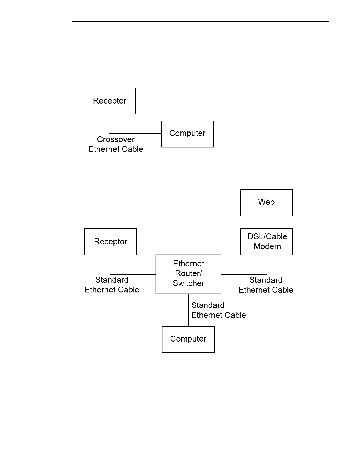
Connecting: Is my computer’s Ethernet port already in use?
You computer’s Ethernet port may already be in use if you’re connected to a cable/DSL modem or to an
existing network. Check to see whether or not you’re already using your computer’s Ethernet port, and proceed
as follows:
• If your computer’s Ethernet port is not in use, you can connect Receptor directly to your computer using a
“special” Ethernet cable known as a ‘crossover Ethernet cable.’ This cable is available from most computer
supply stores and differs from a standard Ethernet cable. Always make sure, when connecting Receptor
directly to a computer (without going through a router/switcher) that you use a crossover Ethernet cable.
• If your computer’s Ethernet port is in use, that means you’ll have to use an Ethernet router/switcher to
connect Receptor and your other Ethernet devices to your computer. Ethernet routers/switchers are widely
available from most computer supply stores. Follow the instructions that come with your router/switcher
and be sure to use standard Ethernet cables (not crossover cables) when connecting all your devices.
1: Quick Start 19 Receptor Manual
Page 20

Mounting: What computer Operating System am I using?
Now that you’ve connected Receptor to your computer, you’ll need to ‘mount it’ on your computer. All this
means is that you want to see the contents of Receptor’s hard drive on your computer just as you see its own
hard drive. This way, you’ll be able to transfer files back and forth between your computer and Receptor.
Naturally, every computer operating system has its own way of doing this and, while it isn’t the goal of
this manual to explain every computer’s networking methodology, Chapter 12, “Connecting Receptor to a
Computer” contains instructions for mounting Receptor with the following methods and operating systems:
• Mac OS X Panther (using either AppleTalk or Samba)
• Mac OS X Jaguar (using either AppleTalk or Samba)
• Mac OS 9 (using AppleTalk)
• Windows XP (using Samba)
• Windows 2000 (using Samba)
Remote Control: Seeing Receptor on your Computer’s monitor
One of the many cool things about connecting Receptor to your computer is that you can remotely control
Receptor’s graphical user interface using your computer’s keyboard, mouse, and monitor — just as if you had
plugged these directly into Receptor! This is very handy for live performance, where you can use a laptop
computer to control your Receptor.
To do this, you must first copy the Remote Control from your Receptor CD onto your computer’s hard disk and
install it. Once the Remote Control application has been installed to your computer, you can use it to remotely
control Receptor at any time. Receptor does not even have to be mounted on your computer in order to use the
Remote Control application. For more information, see “Remote Control of Receptor” on page 174.
How can I integrate Receptor into my recording environment?
1 Connect Receptor to your computer exactly as you would connect a traditional sound or effects module.
That is, connect a MIDI cable from the MIDI OUT port on your computer’s MIDI interface to Receptor’s MIDI IN port.
Connect another MIDI cable from the MIDI IN port on your computer’s MIDI interface to Receptor’s MIDI OUT port.
Connect Receptor’s audio output (either analog or digital) to your mixer or, if you’re mixing on your computer,
connect Receptor’s audio output to your computer’s audio interface. Should you also wish to use Receptor as an effects
processor, connect instruments and/or a couple of your computer’s audio outputs to Receptor’s audio inputs.
2 In your sequencer, define Receptor as a MIDI device and, if desired, label your audio interface’s audio
connectors as belonging to Receptor.
3 You may find it most convenient to configure Receptor using its graphical user interface. To do so,
either plug a keyboard, mouse, and monitor directly into Receptor or use the Receptor Remote Control
application to control Receptor from your desktop computer.
To learn more about connecting Receptor to your computer and controlling it with the remote control application, see
“How and why do I network Receptor to my computer?” on page 18.
4 In your audio sequencer, assign a couple of tracks to play Receptor on different MIDI channels. If you’re
recording Receptor’s output back into your sequencer, make sure to activate the input assigned to
Receptor on your computer’s audio interface.
1: Quick Start 20 Receptor Manual
Page 21
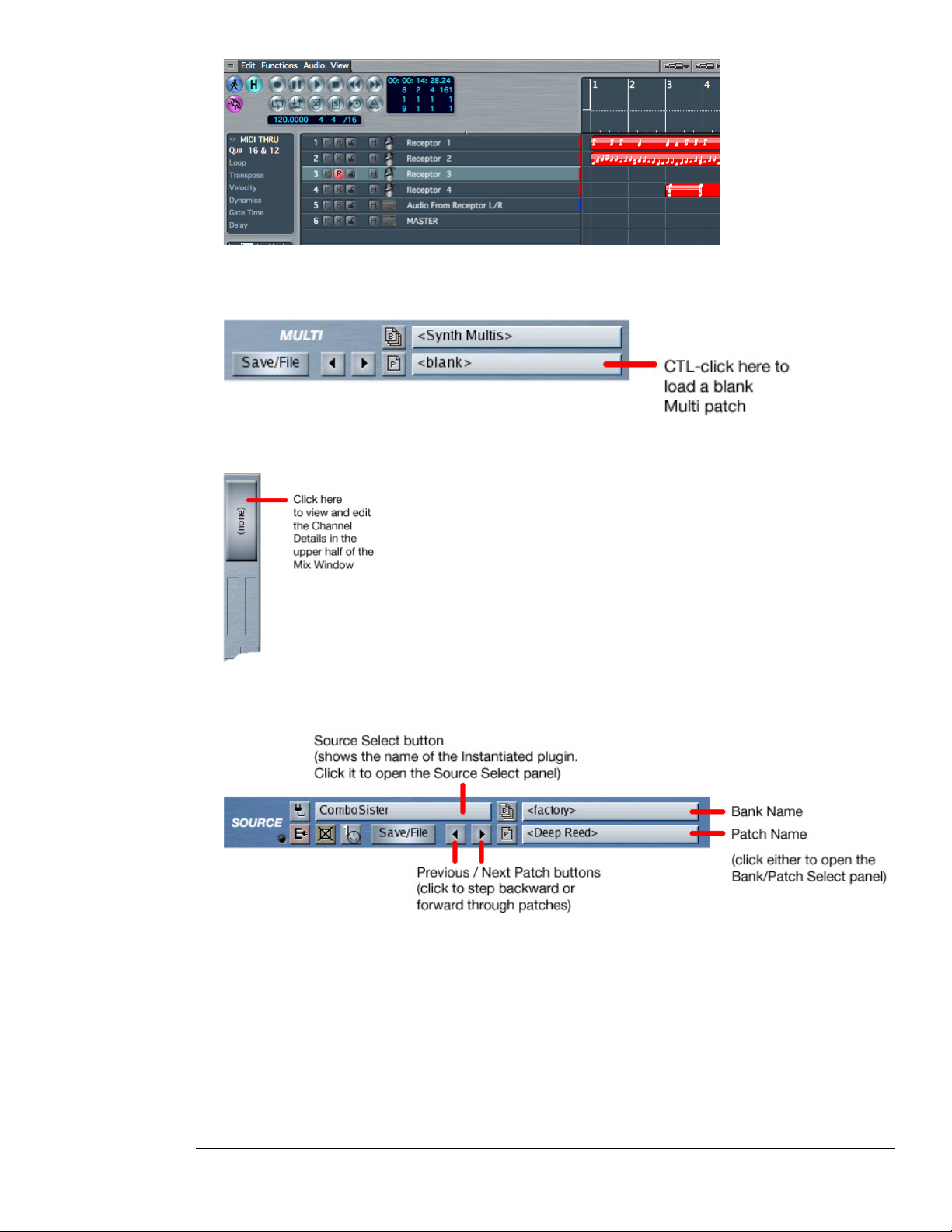
--- Multiple Receptor tracks as shown in Apple Computer’s Logic Audio sequencer ---
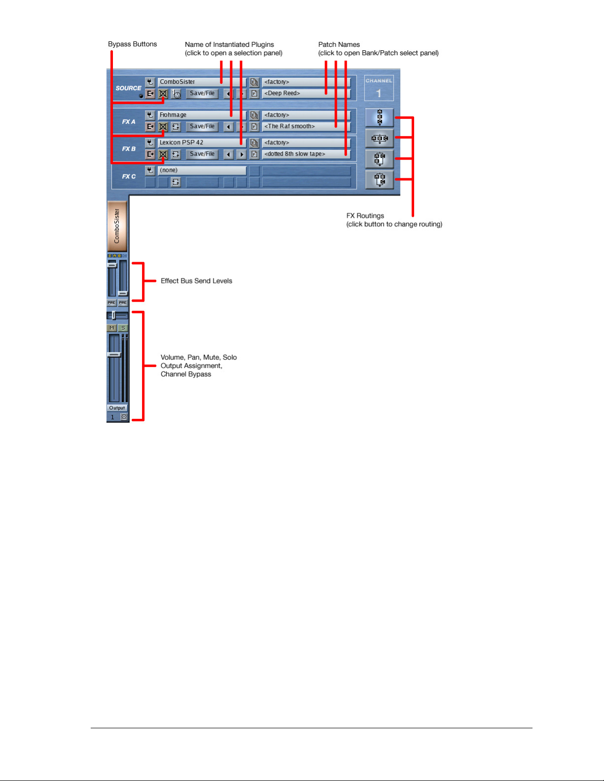
5 On Receptor, CTL-click on the Multi Patch name to load a blank Multi patch into Receptor.
6 On Receptor, click the big “(none)” button on a channel.
The channel details appear at the top of the window.
7 Click the Source Select button.
The Source Select panel opens.
8 In the Source Select panel, click the plugin you want to instantiate on that channel. Use the bank/patch
selectors to select the desired patch
9 If desired instantiate effects plugins for one or more of the channel’s insert FX slots and select the desired
patches. And, if you use insert FX, select their desired routing using the FX routing buttons.
10 Use the channel’s standard Volume and Pan faders as you would on a traditional mixer. You can even set
up effects sends inside Receptor and Mute, solo, or bypass them.
1: Quick Start 21 Receptor Manual
Page 22
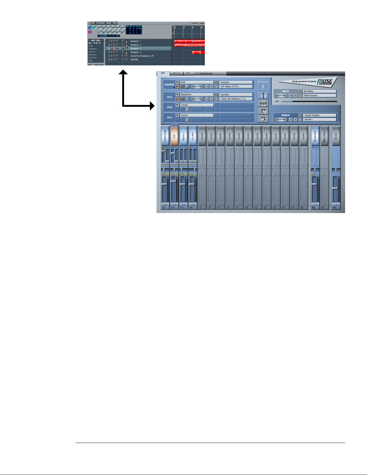
11 By default, each Receptor channel listens to the like-numbered MIDI channel (though you can override
this). But, for now, instantiate different plugins on each channel corresponding to the MIDI track you
assigned in your sequencer.
In the following example, Track 1 in Logic is assigned to Receptor MIDI channel 1, which is configured to play the
Combo Sister VSTi. Track 2 is assigned to Receptor MIDI channel 2, which is configured for Eve; Track 3 plays Albino
2, and Track 4 plays CS-80v.
1: Quick Start 22 Receptor Manual
Page 23
How do I demo and buy premium plugins?
Receptor ships with a nice collection of freeware, but you’ll eventually want to use some commercial plugins.
Receptor protects these with Pace’s iLok—a USB “key” that stores licenses for all your commercial plugins.
Receptor ships with many commercial plugins pre-installed with 30-day demo periods. You can identify a
commercial plugin demo by opening a plugin select panel and looking for any plugin name that begins with
[##].
1 Instantiate a demo plugin (whose name begins with [##]).
2 A dialog box (or LCD) asks if you want to start the demo period—choose “YES.”
You have 30 days to demo the plugin. The prefix counts down the number of days remaining in the demo period. When it
expires, the plugin will no longer instantiate and its name will have a [--] prefix.
3 If you wish to purchase the plugin, go to www.plugorama.com and follow the online purchase instructions
to transfer a license on your iLok. While you’re at plugorama.com, be sure to check for new plugins—
they’re being added all the time.
1: Quick Start 23 Receptor Manual
Page 24

1: Quick Start 24 Receptor Manual
Page 25
2 Receptor Architecture
Receptor is a 16 channel multitimbral virtual sound module and effects unit. Its ability to actually achieve 16
channels of playback is dependent on both the type and number of plug-ins used and their processing demands.
Instruments, Busses, and the Master Output
Receptor contains 19 channels: 16 instrument channels, two dedicated effects busses, and a master bus. These
are discussed in the following sections.
Instrument Channels
Each of the 16 instrument channels can have, as its source, either an internal VSTi or an audio input. Each
instantiated VSTi (or audio input) is routed through a dedicated trio of VST effects, which can be configured in
any series/parallel combination. The output of this effects stack can then be bussed (pre- or post-fader) to two
different effects busses, or it can be sent to the master bus, or to any of the dedicated hardware outputs.
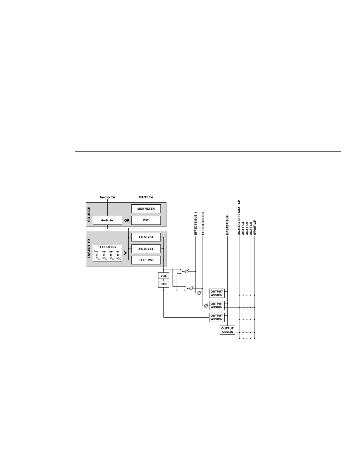
--- Standard Instrument Channel Architecture (x16) ---
Receptor functions like a 16-channel mixer with built-in instruments, insert effects, and effect sends. Its basic
signal flow, which you can follow in the previous illustration, contains the following elements:
• SOURCE:
Receptor can play up to 16 simultaneous sound sources, each assigned to one of its 16 instrument channels.
An instrument’s sound source can be either an internal VSTi or one of Receptor’s audio inputs. If an
internal VSTi is used, the incoming MIDI channel can be remapped to control a specific VSTi channel or
allow MIDI “stacking” of synths.
2: Receptor Architecture 25 Receptor Manual
Page 26
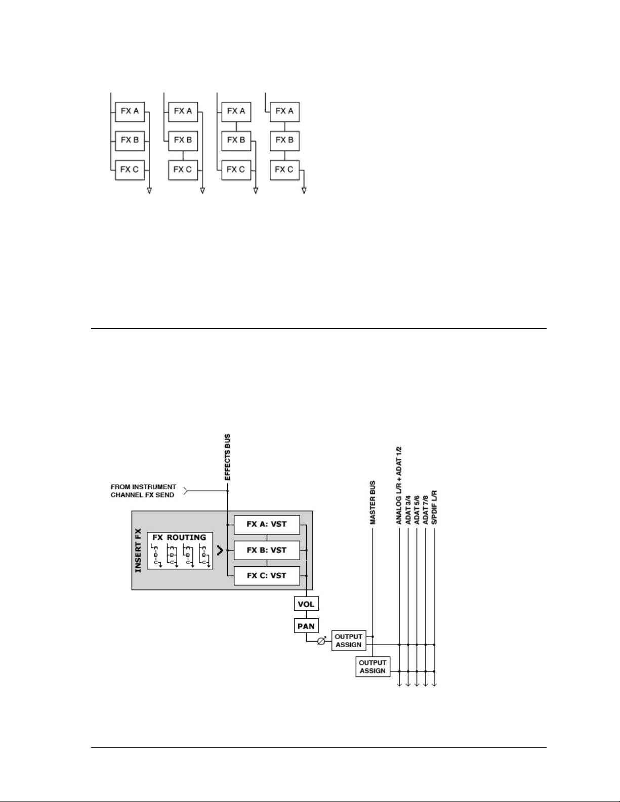
• INSERT FX:
Each of Receptor’s 16 instrument channels contains 3 “insert” effects to which you can assign any VST.
Routing buttons let you arrange these three FX in any series/parallel combination. Additionally, you can
switch their positions, copy other effects to them, and bypass any effect.
--- The different Insert FX routing options ---
• EFFECT SENDS:
Each Receptor channel has two effect sends, either of which can be configured pre or post fader. These
sends are sent to two dedicated effect bus channels as described in the next section, “Effects Bus
Channels.”
• VOLUME /PAN:
Each instrument channel has its own MIDI controllable volume and pan (or balance for stereo instruments).
Effects Bus Channels
Receptor has two dedicated stereo effects busses, each of which contains 3 ‘insert’ type effects to which you can
assign any VST. Routing buttons let you arrange these three FX in any series/parallel combination. Additionally,
you can switch their positions, copy other effects to them, and bypass any effect.
Effects busses are the ideal way to instantiate an effect (such as Reverb or Delay) that you may want to apply to
numerous instrument channels, but in varying degrees. You may route the output of each effects bus to either the
master bus or to any hardware output.
--- Effects Bus Architecture ---
2: Receptor Architecture 26 Receptor Manual
Page 27

Master Channel
Receptor’s Master Bus channel has its own trio of 3 dedicated insert FX, which are perfect for applying
compression or limiting to an entire mix. As with the insert FX on the Instrument and Bus channels, these can
be arranged in any series/parallel combination and the output of the master bus can be routed to any hardware
output.
Patch Hierarchy
Receptor has an intelligent patch hierarchy that uses the following patch types:
• VST (.fxp) Patches - each type of VST instrument or effect can store and recall patches in standard .fxp
format.
• Single Patches - Receptor allows you to store an entire Instrument channel (one Source and three FX
assignments plus their patches) as a “Single patch.” This is a quick way to recall commonly used “super
patches”, such as guitar processing patches that process the signal through all three insert effects, or
synthesizer patches that rely on VST FX processing (such as flangers or delays) to achieve a particular
sound.
• Multi Patches - Receptor can store an entire configuration (all 19 channels, their plugin assignments, and
their mix parameters) as a Multi patch. This is particularly useful for creating big “stacked” sounds that
combine multiple synthesizers, or for MIDI sequencing, where each instrument channel is controlled by a
different MIDI channel.
The following sections contain more information about each patch format and what, specifically, it stores.
VST (.fxp) Patches
Although many plugins have their own internal patch management interfaces, they also are designed to save and
load patches stored as VST standard .fxp patches.
Any time you instantiate a plugin, you will be able to select which .fxp patch you want to load into that plugin.
Unlike a computer-based plugin player, Receptor organizes these .fxp patches into MIDI-compatible banks and
patches.
IMPORTANT: To insure consistent operation of Receptor, always use Receptor’s patch management menus
and not any patch management facilities built into a specific plugin. The reason for this is that .fxp patches
are controlled from a host application level. Receptor manages your .fxp files in such a way that you may have
MIDI selectable banks and patches (just like a hardware synth). Receptor automatically extracts any patches
that are built in to a plugin and creates a factory bank for that plugin, so you never have to worry that you’re
“missing” some patches by using Receptor’s patch management tools.
Single Patches
Single patches store the configuration of a single Instrument Channel (as defined previously). This means that a
Single patch stores an instrument channel’s:
• Source assignment
• Patch (.fxp) data loaded into that Source plugin
• All three Insert FX assignments
• Patch (.fxp) data loaded into each Insert FX plugin
• FX routing
Mix parameters such as Mute, Solo, Volume, and Send Level are not stored within a Single, since these
parameters are all dependent on the context in which you use the Single patch.
For this same reason, Single patches do not store the “Listen To MIDI Ch” setting (as discussed in “SOURCE:
Listen to MIDI Ch” on page 49). All these parameters are, however, saved as part of a Multi patch, which is
discussed in the next section.
2: Receptor Architecture 27 Receptor Manual
Page 28

IMPORTANT: Notice that Single patches store the patch data used for each plugin. This way, if you ever
delete, rename, modify, or move a .fxp that was used to create the Single patch, you have no need to worry
-- your Single patches will always sound exactly as they did when saved, regardless of what you do to the .fxp
patches that were used to create the Single patch originally. So, even though Single patches always attempt to
display the name of the .fxp files used to create them, keep in mind that the patch data saved with the Single
may not be the same as the data saved in the named .fxp file -- again, this is to protect your Single patches from
inadvertently changing if you change a .fxp that was used in its creation.
You can think of a Single patch as a sort of “super-instrument,’ since it contains not only an audio source,
but also its insert effects. One of the wonderful things about Single patches is that, by recalling one, you
automatically instantiate every plugin required by that patch.
Multi Patches
Multi patches store an entire Mixer setup, including all Source and FX assignments, patch data, mix parameters,
output routings, and the following Setup parameters:
• Master Transpose
• Tempo Source
• Tempo BPM
• Time Signature
NOTE: Setup mode parameters are discussed fully in “SETUP Button” on page 59.
You can think of Multi patches as “snapshots” of your entire Receptor mixer, which makes them quite useful
for creating big “stacked” sounds that combine multiple synthesizers, or for MIDI sequencing, where each
instrument channel is controlled by a different MIDI channel.
IMPORTANT: Notice that Multi patches store the patch data used for each plugin. This way, if you ever delete,
rename, modify, or move a .fxp that was used to create the Multi patch, you have no need to worry -- your Multi
patches will always sound exactly as they did when saved, regardless of what you do to the .fxp patches that
were used to create the Multi patch originally. So, even though Multi patches attempt to display the name of the
.fxp files used to create them, keep in mind that the patch data saved with the Multi may not be the same as the
data saved in the named .fxp file -- again, this is to protect your Multi patches from inadvertently changing if
you change a .fxp that was used in its creation.
2: Receptor Architecture 28 Receptor Manual
Page 29
3 Receptor Hardware
The following sections discuss Receptor’s hardware components.
Front Panel
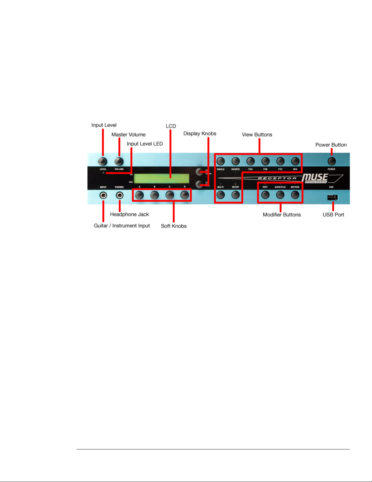
--- Receptor Front Panel ---
Receptor’s front panel contains, from left-to-right:
• Guitar / Instrument Input
Use this input to plug a guitar, instrument or microphone into Receptor.
• Input Level Knob
Use this to adjust the signal level of the instrument input. For the best signal-to-noise ratio, turn up the level
until the loudest sounds just barely cause the Level LED to turn red, then back off slightly on the level, so
the LED only ever turns yellow.
• Input Level LED
This LED glows green, yellow, or red depending on the amount of input signal present. If the meter turns
red, turn down the Input Level knob until the LED is yellow. Specifically, the LED glows green at -40 dB,
yellow at -9 dB, and red at 0 dB.
• Headphone Jack
This 1/4” stereo jack duplicates the signal present at the main L / R jacks at the rear of the unit.
• Master Volume Knob
This knob modifies the total overall output level for Receptor (both for the headphones and the rear analog
outputs). It’s completely independent of the MIDI volume levels and is a quick way to adjust the overall
output level of Receptor.
• LCD
Use this 24 character x 2 line LCD to navigate through Receptor’s various parameters and configurations.
To learn more about this ‘window into Receptor,’ see “LCD and Display Knobs” on page 37.
3: Receptor Hardware 29 Receptor Manual
Page 30

• Display Knobs
Use these 2 continuous rotary encoders with built-in push buttons for controlling the LCD. To learn more
about these knobs, see “LCD and Display Knobs” on page 37.
• Soft Knobs
Use these 4 continuous rotary encoders with built-in push buttons for instant parameter editing. To learn
more about these buttons, see “EDIT: Using the Soft Knobs” on page 74.
• View Buttons
There are 8 View buttons with indicator LEDs. The LEDs are used to indicate which parameter page you’re
currently viewing in the LCD. To learn more about these buttons, see Chapter 5, “View Buttons in Depth.”
• Modifier Buttons
There are 3 Modifier buttons with indicator LEDs. These LEDs are of a different color than the 8 View
button LEDs. Pressing one of these buttons modifies the concurrently lit View button. To learn more about
these buttons, see Chapter 6, “Editing, Saving, and Metering.”
• USB Port
This is one of five USB ports on Receptor (the others are on the rear panel). Use the USB ports to plug in
optional accessories, such as keyboard, mice, musical keyboards, control surfaces, hard drives, etc.
• Power Button
As you might expect, this button is used to turn Receptor on or off. What you might not expect is that
the word “power” refers both to the electrical implications of the button and to its capabilities. See the
following section for more information:
Power Button Operation
Receptor’s POWER button has multiple features that belie its seemingly innocuous functionality. Specifically:
To turn Receptor ON:
1 Press the button once. Receptor will perform some self-diagnostics, then cycle through a startup process.
To turn Receptor OFF:
1 Press the power button twice within a second.
That’s right, you read correctly. You need to double-click the power button in order to shut down Receptor. There is
method to our madness, however. This is a safety measure that prevents you from accidentally turning the unit off in a
live situation.
Receptor will go through a nice orderly shut down, which insures that, when you turn it back on, it will be in exactly the
same state as when you turned it off.
To force Receptor to turn OFF (even if it’s frozen):
1 Press and hold the Power Button for 4 seconds and Receptor will shut down.
If Receptor ever crashes and double-pressing the POWER button doesn’t shut the unit down, then use this procedure to
shut down Receptor.
To restart Receptor without going through a lengthy power-off / power-on cycle:
1 Triple-click the POWER button (quickly, like you would do with a mouse).
When you do this, Receptor will go blank for a second while it restarts the Receptor application. Triple clicking does
not cause the entire Operating System to shut down and reload. As such, the operation is similar to quitting and
restarting an application on a desktop computer, without shutting off the entire computer.
TIP: Triple-clicking is always a good thing to try if Receptor doesn’t seem to “behave” as you expect, or if you ever
install plugins, patches, or samples and, for some reason, they don’t appear in Receptor. The triple-click procedure is
very quick — much faster than turning the unit off and back on.
3: Receptor Hardware 30 Receptor Manual
Page 31
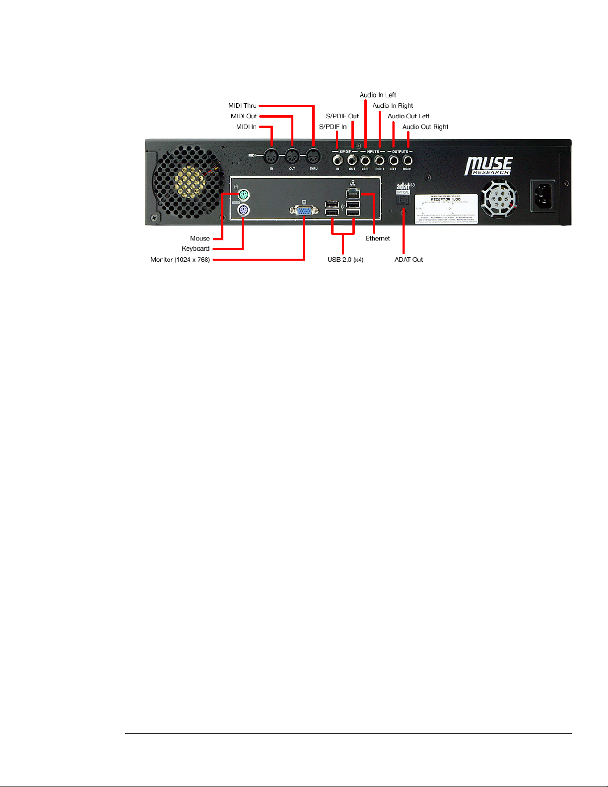
Back Panel
The following illustration shows Receptor’s rear panel:
Top row, left-to-right:
• MIDI In, Out, and Thru ports
• S/PDIF In and Out
• Audio Inputs (Left, Right): 1/4” balanced connectors
• Audio Outputs (Left, Right): 1/4” balanced connectors
Bottom of box, left-to-right:
• Mouse port
• Keyboard port
• VGA connector for 1024 x 768 monitor
• 4 USB 2.0 connectors for attaching external USB peripherals, such as an iLok, keyboard, mice, musical
• 100Base-T Ethernet Connector
• ADAT output
--- Receptor Back Panel ---
keyboards, control surfaces, hard drives, etc.
Under the Hood
Receptor is housed in a standard dual unit rack mount enclosure. Inside is a 40 GB hard disk and 256MB of
PC2700 DDR RAM (user-expandable to 2 GB).
SAMPLER USERS: If you plan to employ sampler plugins, and you use large numbers of samples or large
sample libraries with Receptor, you will definitely want to increase the amount of RAM in the unit. You have the
following options:
• Add one stick of 256MB DDR PC2700 RAM for a total of 512 MB
• Add on stick of 512 MB DDR PC2700 RAM for a total of 768 MB
• Add one stick of 1 GB DDR PC2700 RAM for a total of 1256 MB
• If you wish to increase RAM beyond 1256 MB, remove the existing 256 MB module and replace it with a
higher capacity stick (up to 1 GB), for a maximum of 2 GB total RAM.
3: Receptor Hardware 31 Receptor Manual
Page 32

Connecting a Musical Keyboard
You may connect either a MIDI keyboard or a USB Keyboard to Receptor. If you use Receptor’s MIDI IN port,
then any type of standard MIDI keyboard is supported. If you chose to use Receptor’s USB port for MIDI,
then (as of this writing) only the M-Audio Oxygen-8 and Radium keyboards have been tested. Check the
museresearch.com web site for additional keyboard support.
IMPORTANT: You should shut down Receptor before unplugging a USB keyboard. If Receptor is powered on
and you disconnect and then reconnect a USB keyboard, Receptor will, in most instances, no longer be able to
“see” the reconnected USB keyboard.
3: Receptor Hardware 32 Receptor Manual
Page 33

Using Receptor’s Front Panel
This section discusses how to use Receptor as a stand-alone unit
using only its own front panel buttons, knobs, and LCD.
Front Panel 33 Receptor Manual
Page 34

Front Panel 34 Receptor Manual
Page 35
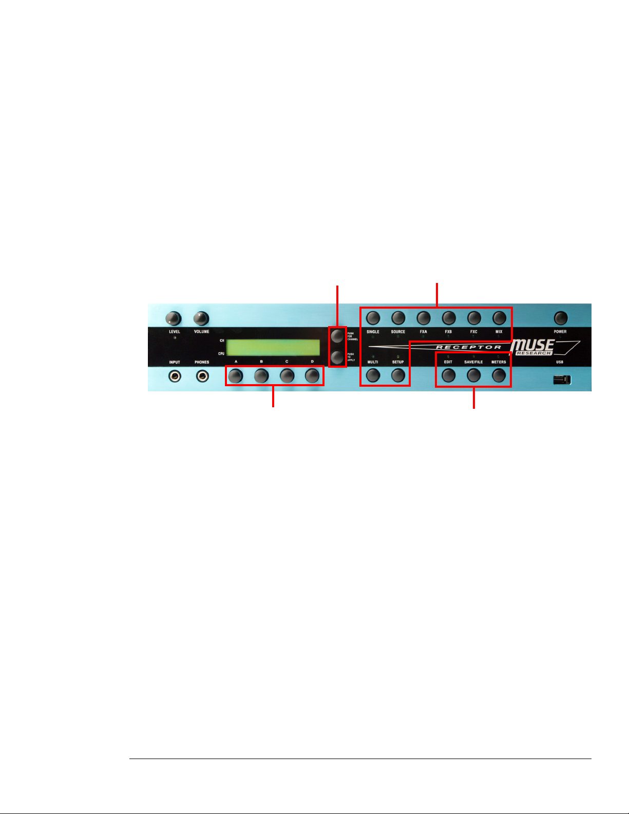
4 Front Panel UI Overview
Although you can edit Receptor graphically by connecting a dedicated keyboard, mouse, and monitor or by
connecting it to a computer via Ethernet, it’s designed to be completely and intuitively operated using only its
front panel. The following sections discuss the basic operation of Receptor’s front panel user interface, while
the remaining chapters delve deeply into the details of the configuration process.
Front Panel Interface Basics
Receptor’s front panel interface couples a 24-character x 2-line LCD with eight dedicated View buttons, a trio
of Modifier buttons, a pair of navigational display knobs, and four soft knobs.
Display Knobs View Buttons
Soft Knobs
These basic UI components are described in the following sections.
Modifer Buttons
4: Front Panel UI Overview 35 Receptor Manual
Page 36
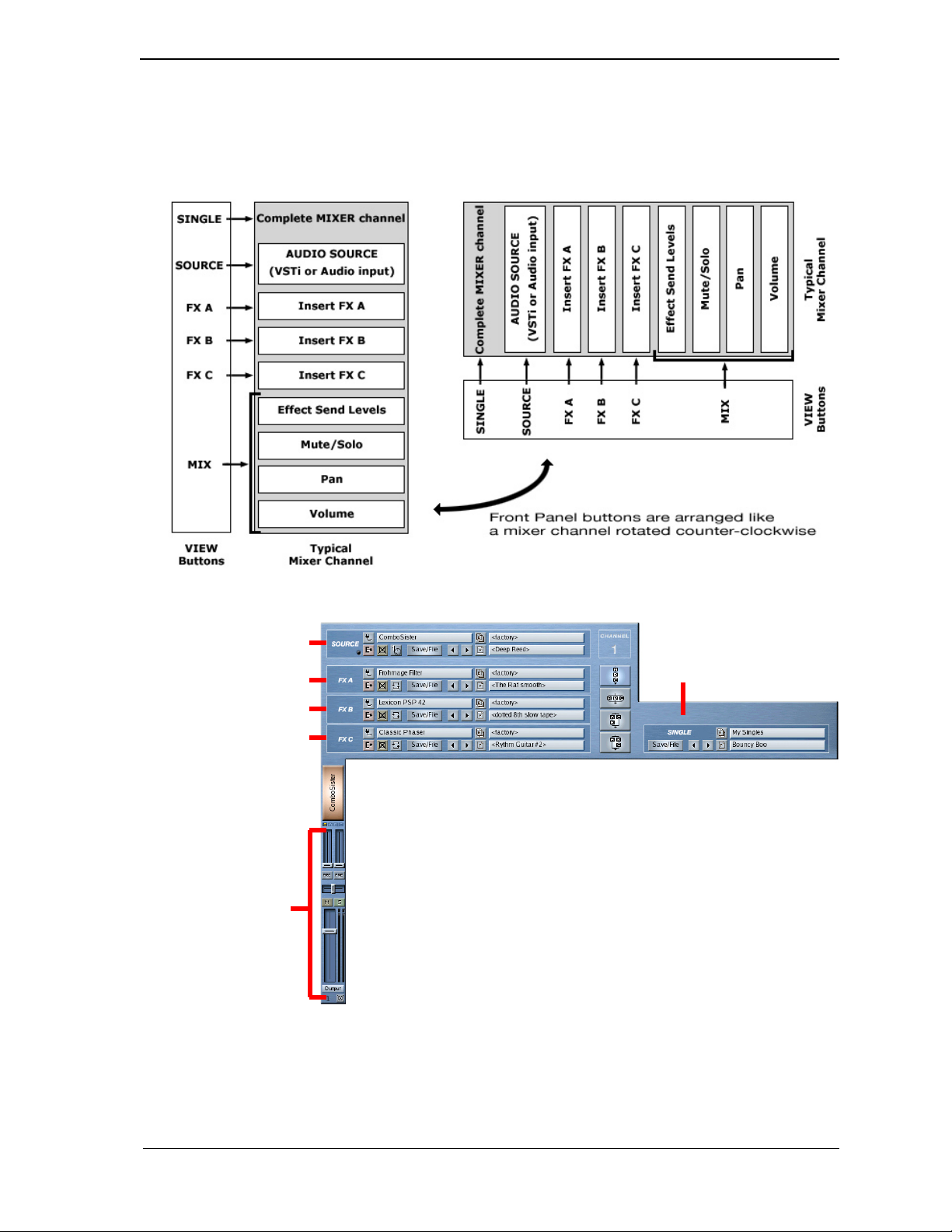
View Buttons
Press the various View buttons to select which subset of parameters are displayed in the LCD. Each View button
has a corresponding LED, so you always know which parameter subset you’re viewing.
It may help to visualize the top row of View buttons as a horizontal mixer strip, where SINGLE = a complete
mixer channel arrangement, SOURCE = the audio input, FX A, B, and C = inert FX, and MIX = send level/
mute/solo/pan/volume:
If you’re familiar with Receptor’s graphical user interface, the relationship between it and the View buttons is
shown in the following illustration.
SOURCE button
SINGLE button
FX A button
FX B button
FX C button
MIX button
4: Front Panel UI Overview 36 Receptor Manual
Page 37
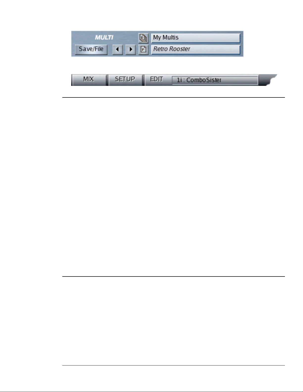
The MULTI button corresponds to Receptor’s MULTI patch area, which is where the entire Receptor
configuration (across all channels) is managed and recalled.
... and the SETUP button is used to access to Receptor’s Setup options, such as networking, audio, and MIDI
configuration.
Modifier Buttons
Press one of the three Modifier buttons to apply a further set of options to the selected View button. Basically, a
Modifier button acts upon the patch or signal represented by the correspondingly lit View button. For example:
EDIT Button Overview
• If a SOURCE, FX A, FX B or FX C button is lit and you press the EDIT button, you’ll be able to edit
various VST parameters assigned to those slots.
• If the SETUP button is lit and you press the EDIT button, you’ll trigger a “panic” function by sending an
“All Notes Off” message to all internal instrument channels, silencing them completely.
• If the MULTI, SINGLE or MIX buttons are lit and you press the EDIT button, no parameters are displayed.
For detailed information, see “EDIT Button” on page 74.
SAVE/FILE Button Overview
• If a MULTI, SINGLE, SOURCE, FX A, FX B or FX C button is lit and you press the SAVE/FILE button,
you’ll be able to save, delete, copy or rename a bank or patch of the corresponding type.
• If the SETUP button is lit and you press the SAVE/FILE button, you’ll see an overview screen showing
Receptor’s Channel Status.
• If the MIX button is lit and you press the SAVE/FILE button, no parameters are displayed.
For detailed information, see “SAVE/FILE Button” on page 75.
METERS Button
• If a MULTI, SINGLE, SOURCE, FX A, FX B, FX C or MIX button is lit and you press the METERS
button, you’ll be able to monitor the signal level at the output of the correspondingly lit slot.
• If the SETUP button is lit and you press the METERS button, you’ll load a blank multi patch into Receptor.
For detailed information, see “Meters Mode” on page 82.
LCD and Display Knobs
The 2-line display works very consistently in all views and modes. In general it is controlled by the two knobs
to its right:
• Top Display Knob
The top display knob controls the top line of the display and is almost always used to scroll through a list
of parameters, whose names appear on the top line of the LCD. By pushing the top display knob, it can be
used to set a different Channel Number as discussed in “Channel Number” on page 38.
• Bottom Display Knob
The bottom display knob controls the bottom line of the display and is almost always used to select a value
for the parameter name shown in the top line of the LCD. Whenever a parameter value flashes, it indicates
that you must press the bottom display knob in order to apply your selection.
4: Front Panel UI Overview 37 Receptor Manual
Page 38
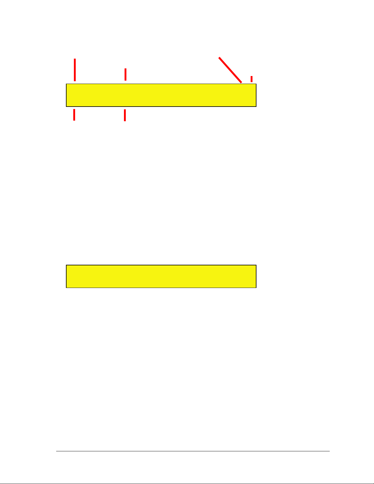
If you understand these basic functions, you can quickly and effortlessly navigate through Receptor’s hierarchy
using only this 2-line display.
More Parameters
Channel Number
to the left
Parameter Name
Move Parameters
to the right
0 1 P a r a m e t e r < >
III III V a l u e
CPU Usage
--- Typical LCD Interface Components ---
The following sections will discuss the various LCD interface components:
Parameter Value
Channel Number
This always appears at the top left of the display to indicate which channel you’re currently editing. When
Receptor is in SINGLE, SOURCE, FX A, FX B, FX C, or MIX views, the channel will indicate which of
Receptor’s 19 channels you’re editing:
• 01-16 (indicating Receptor Channels 1-16)
• B1, B2 (indicating Receptor’s Effects Bus 1 and 2 channels)
• M (indicating Receptor’s Master output channel)
To change the current Channel Number:
1 Press the top display knob to enter Channel Select mode.
The top line of the display reads Select Channel and an arrow points toward the LCD’s channel indicator, which
is now underlined.
0 1 < - - S e l e c t C h a n n e l
III III
2 Rotate the top display knob to change the channel and press it again when finished.
If you don’t press the top display knob to exit Channel Select mode, Receptor will still apply the channel change and
automatically exit this mode after a few seconds.
Additionally, when Receptor is in MULTI view, the channel number displays:
• MU (indicating that you’re viewing MULTI patch parameters, which are independent of a channel
selection)
When Receptor is in SETUP view, the channel number displays:
• SU (indicating that you’re viewing SETUP parameters, which are independent of a channel selection)
CPU Usage
Unlike a traditional fixed-architecture synth, Receptor’s performance varies greatly depending on the type and
number of instruments and effects you instantiate. For example, loading a complex reverb plugin requires far
more of Receptor’s internal CPU power than a simple digital delay. Similarly, loading three “analog” synths
requires more CPU usage than one. In addition, the CPU usage of most VST instruments varies depending on
how many simultaneous notes you’re currently playing.
4: Front Panel UI Overview 38 Receptor Manual
Page 39
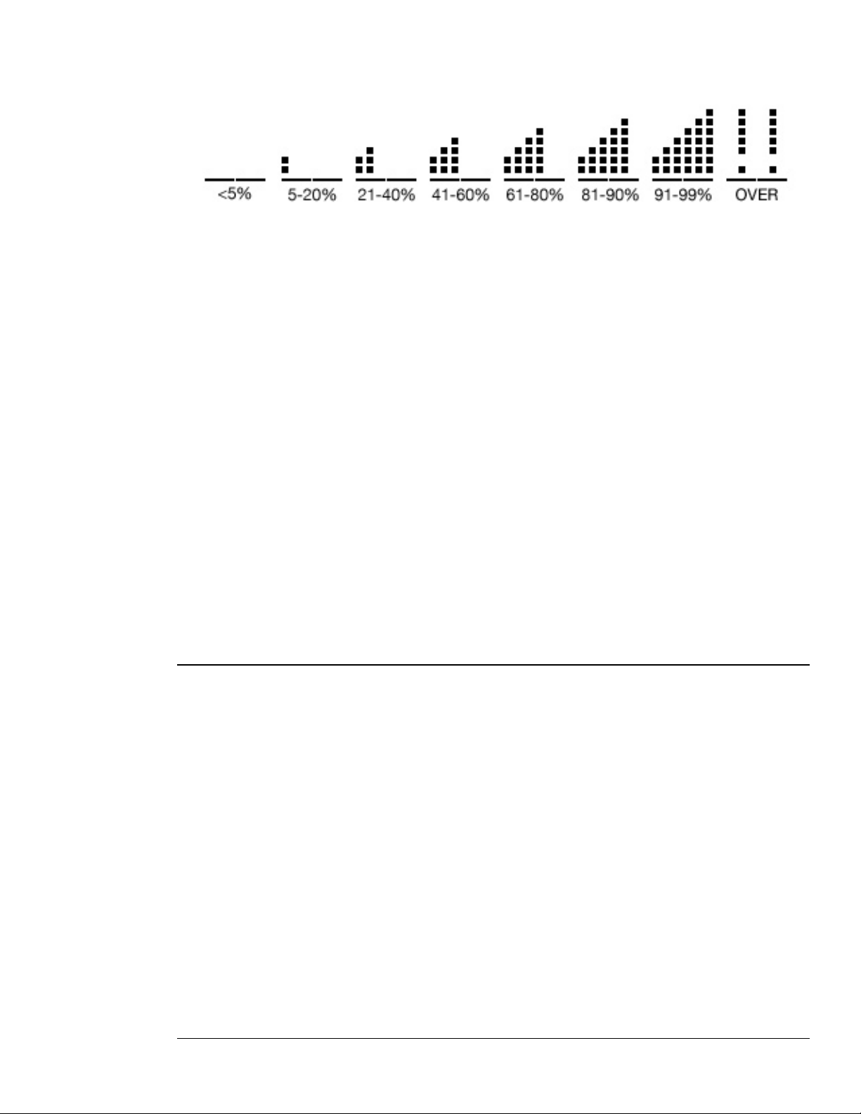
Because of these facts, you’ll always want to keep your eye on Receptor’s CPU usage. This little gauge, which
is almost always visible in the bottom left of the LCD, indicates CPU usage. It occupies the two lower left
characters in the LCD and fills from left-to-right as the CPU usage increases.
--- CPU Gauge and its indication of approximate CPU usage ---
If you overload Receptor’s CPU, the display is replaced by a double set of exclamation points. When this
happens, you should bypass or uninstantiate some plugins (or consider buying more Receptors).
Parameter Name
As mentioned previously, the bulk of the LCD’s top line is used to display parameter names. Scroll through
various parameters by turning the top display knob.
More Parameters Indicator
This little 2-character indicator (at the far right of the top line) lets you know if there are more parameters
available either before or after the parameter you’re currently viewing. The first parameter in a scrolling
list always has a single arrow pointing right (indicating that more parameters are available after it, but that
none come before it). Similarly, the last parameter in a scrolling list always has a single arrow pointing left
(indicating that more parameters come before it, but that none come after it). Parameters in the middle of a
scrolling list have arrows pointing both direction (indicating that more parameters are available both before and
after the current one).
Parameter Value
As mentioned previously, the bulk of the LCD’s bottom line is used to display the value associated with the
parameter named in the top line. If a parameter value is flashing, it indicates that you must press the bottom
display knob in order to activate the parameter change.
Sometimes a portion of a parameter value might be underlined, which helps you see exactly which portion of a
parameter value the bottom display knob is affecting.
Soft Knobs
Whenever you enter Edit Mode for one of the channel views (SOURCE, FX A, FX B, FX C, or MIX), the four
soft knobs are available for controlling up to four edit parameters simultaneously. For example, an “analog
synth” plugin might assign these knobs to control filter frequency, filter resonance, Oscillator frequency, and
FM amount, giving you a fair amount of real-time control over the synthesizer.
For more information about how to use the soft knobs, see “EDIT: Using the Soft Knobs” on page 74.
4: Front Panel UI Overview 39 Receptor Manual
Page 40

4: Front Panel UI Overview 40 Receptor Manual
Page 41
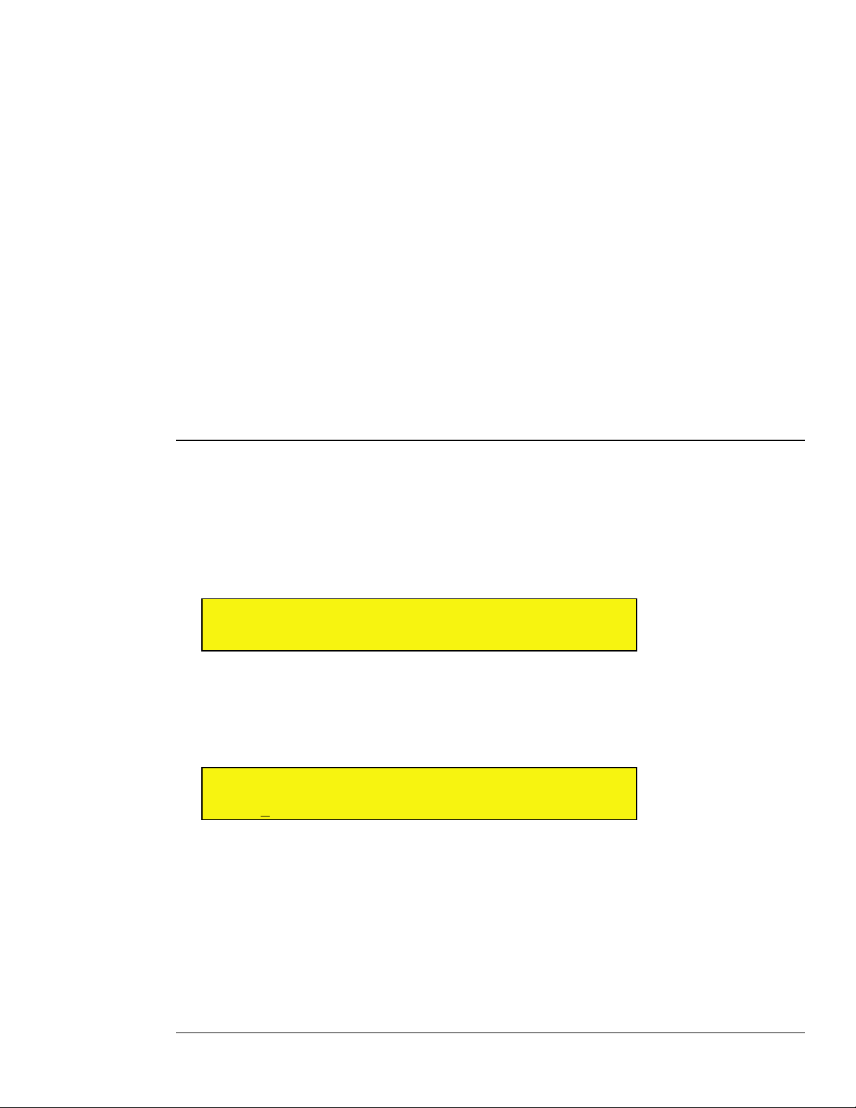
5 View Buttons in Depth
This chapter discusses every View Mode button and its associated set of parameters. You should have a basic
understanding of Receptor’s signal flow architecture and overall front panel operation before reading this
chapter.
MULTI Button
A Multi patch consists of an entire receptor configuration, including all Source and Insert FX assignments on
all Instrument channels, all Effects Bus assignments, the Master channel assignments, and all routings, button
states, and levels. In addition, many relevant Setup parameters are saved with Multi patches (as discussed
on a case-by-case basis in “SETUP Button” on page 59). Multi patches provide a quick, one-step method to
reconfigure your entire Receptor for a new song or set. This section discusses the parameters available when
you press the MULTI button on Receptor.
MULTI: Bank
In order to conform with MIDI standards, patches are stored together in a group, which is called a ‘bank.’
Each bank can hold up to 128 patches. Receptor can store up to 128 banks of Multi patches (for a maximum of
16,384 Multi patches). To select a patch from a particular bank, you must first select the bank, then the actual
patch.
To select a bank and load a Multi patch from that bank:
1 Rotate the top display knob to select the Bank parameter.
M U B a n k < >
III III B a n k : F a c t o r y
2 Rotate the bottom display knob to select the bank you wish to load.
The bank name is flashing
3 Press the bottom display knob.
Receptor shows you the first patch in that bank.
M U P a t c h < >
III III 0 0 1: S p a c e J a m
4 Rotate the bottom display knob to select a patch. The patch name will flash.
5 Press the bottom display knob to load that patch into Receptor.
NOTE 1: You cannot select a bank without also selecting a patch, since a bank is nothing more than a directory
of patches.
NOTE 2: ROM bank names are enclosed in angle brackets, like <this>. When you see a bank name enclosed
in <angle brackets>, it means the bank is a “factory” bank and cannot be overwritten or deleted. For more
information, see “ROM Banks and RAM Banks” on page 127.
5: View Buttons in Depth 41 Receptor Manual
Page 42
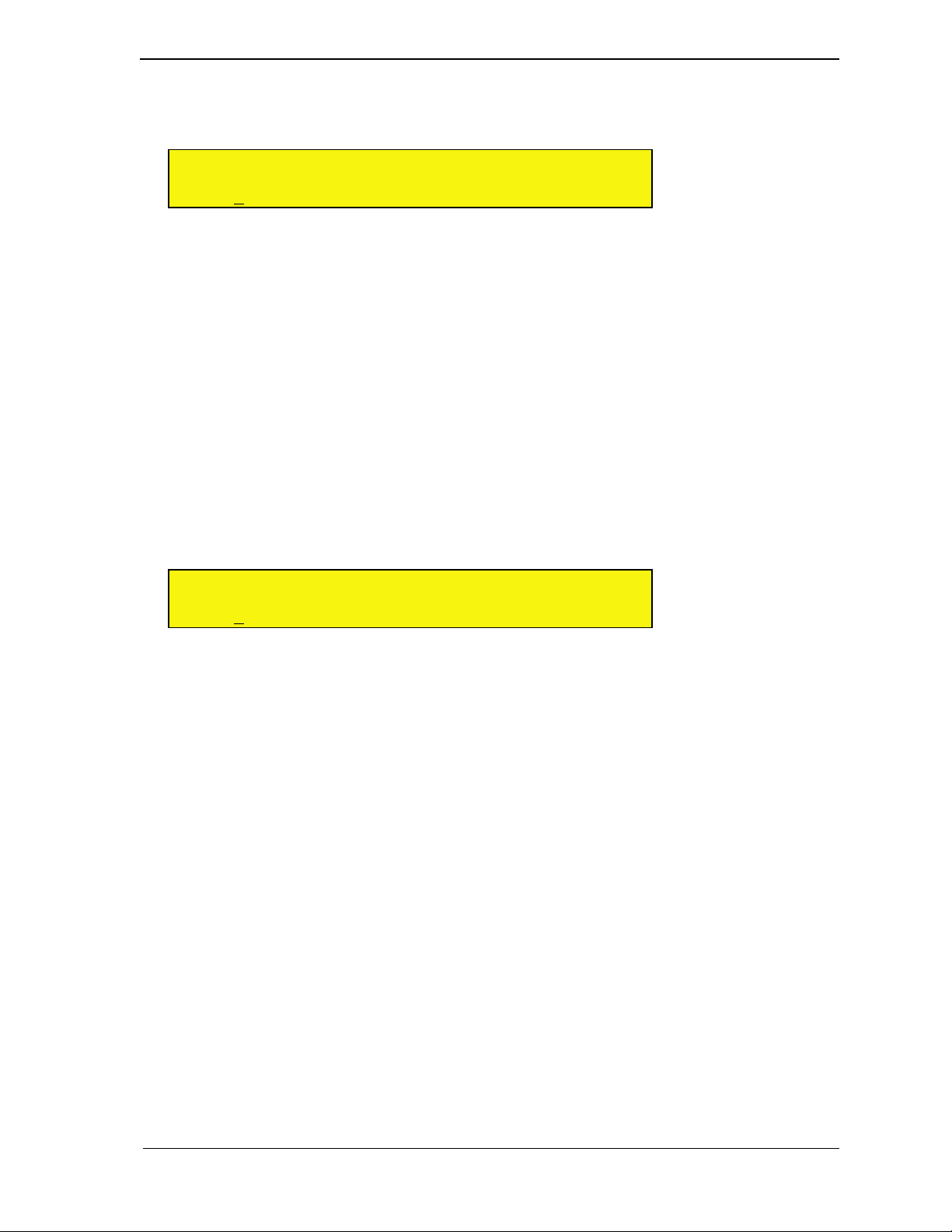
MULTI: Patch
If you want to select a patch from the current bank, rotate the top display knob to select the Patch parameter. If
you want to select a patch from a different bank, it will be fastest to use the Bank parameter discussed above.
M U P a t c h < >
III III 0 0 1 : S p a c e J a m
Rotate the bottom display knob to select the patch you wish to load. The patch name is flashing, indicating you
must press the bottom display knob to actually load the selected patch.
If you’re currently viewing the last patch in a bank, and you turn the bottom display knob another notch
clockwise, Receptor will automatically switch to the next bank and display the first patch within that bank. The
same is true if you’re viewing the first patch in a bank and turn the bottom display knob counter-clockwise.
Essentially, you can scroll through every Multi patch without using the Bank parameter at all! However, if you
have 16,000 Multi patches, we’re quite certain that you’ll want to make use of the Bank parameter.
NOTE 1: Because Multi patches require Receptor to instantiate numerous plugins as well as load each plugin
with the correct parameters, you may experience a bit of a wait -- particularly if some plugins must load
samples from hard disk, or are particularly complex.
NOTE 2: ROM patch names are enclosed in angle brackets, like <this>. When you see a patch name enclosed
in <angle brackets>, it means the patch is a “factory” patch and cannot be overwritten or deleted. For more
information, see “ROM Banks and RAM Banks” on page 127.
NOTE 3: If you have edited a patch in any way, an asterisk (*) replaces the colon (:) between the patch number
and name. When you see an asterisk between the patch number and name, you’ll know that the version currently
in the edit buffer is not what’s saved to disk.
M U P a t c h < >
III III 0 0 1 * S p a c e J a m
If you want to save your patch, press the SAVE /FILE button to save your edits (as described in “SAVE/FILE
Button” on page 75).
Patch Prefixes
If a Multi patch name appears with a [!!] prefix, it means that the Multi is referencing one or more plugins that
cannot be instantiated. Possible reasons for this include:
• You have removed a plugin required by that patch
• That patch was created with a demo plugin that is now expired
• The patch may be referencing an iLok-protected plugin and the iLok may not be inserted properly.
You can scroll through the various Source and FX plugin assignments to look for the problem. It will be easy to
spot, since the questionable plugin(s) will have a prefix before their name that indicates what the problem might
be. That is:
• [XX] before a plugin name means that it’s no longer on Receptor’s hard drive
• [--] before a plugin name means it’s a premium plugin that you must purchase (perhaps because a demo
period expired)
• [##] before a plugin name means the plugin has not yet had its demo period activated
• [??] before the plugin indicates an error, most likely that the iLok is not inserted properly.
5: View Buttons in Depth 42 Receptor Manual
Page 43
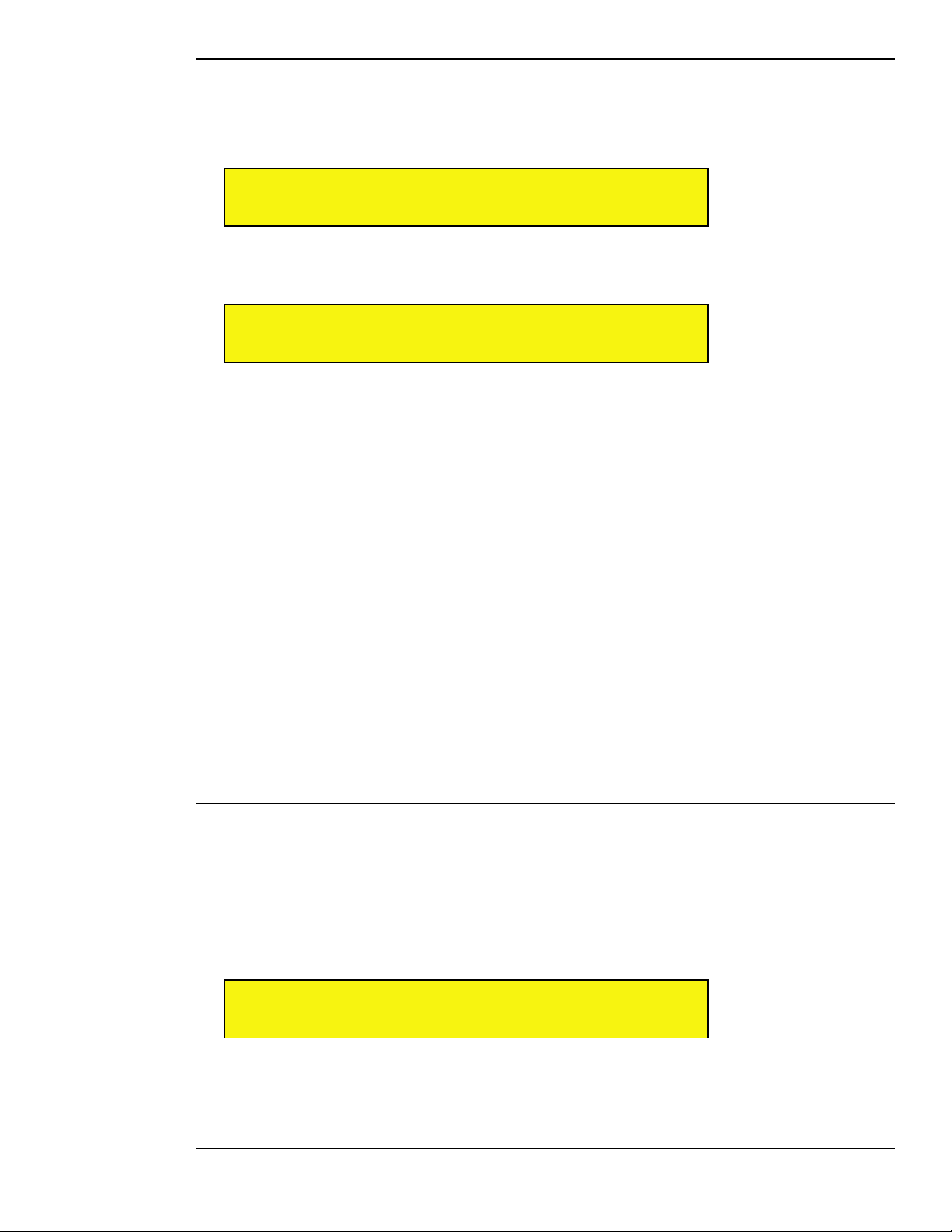
MULTI: Load Blank Patch
Rotate the top display knob to select the Load Blank Patch parameter. This special patch resets your Multi
by uninstantiating every plugin on every instrument channel and returning Receptor to its default configuration.
This is the ideal way to “wipe the slate clean” and start setting up an entirely new Multi patch from scratch.
M U L o a d B l a n k P a t c h <
III III P r e s s k n o b t o l o a d
To initialize the Multi patch, simply press the bottom display knob. All channels will be cleared and the screen
will indicate when the process is finished.
M U L o a d B l a n k P a t c h <
III III L o a d e d
SHORTCUT: Receptor provides a shortcut for loading a blank Multi patch from the front panel. Specifically,
if you press the SETUP button, then press the METERS button, Receptor will automatically load a blank Multi
patch. This is great if you want to quickly set Receptor to a known, empty state.
Force Load a Blank Patch
You can force Receptor to turn on with its blank patch by holding the MULTI button down while the unit turns
on. This is convenient if, in the rare case, Receptor is trying to turn on and load a damaged or corrupted Multi
patch.
NOTE 1: It’s most important to hold the MULTI button during the final stages of initialization. So don’t give up
holding the button until the unit is completely on and the user interface is displayed.
NOTE 2: If a Receptor startup configuration fails to load and the host fails to start, then the next time Receptor
starts up, it will load its empty default state. This is a fail-safe to prevent Receptor from attempting to endlessly
restart in an unstable state.
SINGLE Button
Single patches store the Source assignment, Insert FX assignments and routings for an Instrument Channel.
They also store the patch data for each instantiated plugin, which means your Single patches never “lose their
patch data” if you happen to change or delete a VST patch that was used in creating a Single patch.
SINGLE: Bank
In order to conform with MIDI standards, patches are stored together in a group, which is called a ‘bank.’ Each
bank can hold up to 128 patches. Receptor can store up to 128 banks of Single patches (for a maximum of
16,384 Single patches). To select a patch from a particular bank, you must first select the bank, then the actual
patch.
To select a bank and load a patch from that bank:
1 Rotate the top display knob to select the Bank parameter.
0 1 B a n k < >
III III B a n k : W e b s o u n d s
2 Rotate the bottom display knob to select the bank you wish to load.
The bank name is flashing
3 Press the bottom display knob.
5: View Buttons in Depth 43 Receptor Manual
Page 44
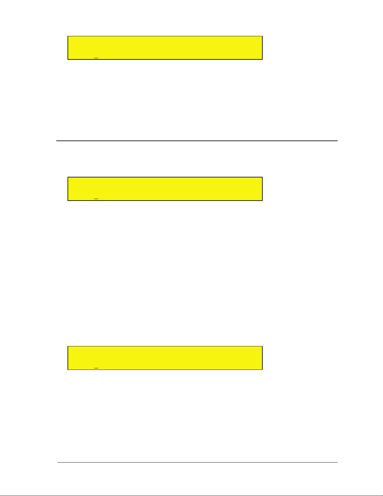
Receptor shows you the first patch in that bank.
0 1 P a t c h < >
III III 0 0 1 : S m a r m y L e a d
4 Rotate the bottom display knob to select a patch. The patch name will flash.
5 Press the bottom display knob to load that patch into Receptor.
NOTE 1: You cannot select a bank without also selecting a patch, since a Bank is nothing more than a directory
of patches.
NOTE 2: ROM bank names are enclosed in angle brackets, like <this>. When you see a bank name enclosed
in <angle brackets>, it means the bank is a “factory” bank and cannot be overwritten or deleted. For more
information, see “ROM Banks and RAM Banks” on page 127.
SINGLE: Patch
If you want to select a patch from the current bank, rotate the top display knob to select the Patch parameter. If
you want to select a patch from a different bank, it will be fastest to use the Bank parameter discussed above.
0 1 P a t c h < >
III III 0 0 6 : A c i d B a s s
Rotate the bottom display knob to select the patch you wish to load. The patch name is flashing, indicating you
must press the bottom display knob to actually load the selected patch.
If you’re currently viewing the last patch in a bank, and you turn the bottom display knob another notch
clockwise, Receptor will automatically switch to the next bank and display the first patch within that bank. The
same is true if you’re viewing the first patch in a bank and turn the bottom display knob counter-clockwise.
Essentially, you can scroll through every Single patch without using the Bank parameter at all! However, if you
have 16,000 Single patches, we’re quite certain that you’ll want to make use of the Bank parameter.
NOTE 1: Because Single patches require Receptor to instantiate numerous plugins as well as load each plugin
with the correct parameters, you may experience a bit of a wait -- particularly if some plugins must load
samples from hard disk, or are particularly complex.
NOTE 2: ROM patch names are enclosed in angle brackets, like <this>. When you see a patch name enclosed
in <angle brackets>, it means the patch is a “factory” patch and cannot be overwritten or deleted. For more
information, see “ROM Banks and RAM Banks” on page 127.
NOTE 3: If you have edited a patch in any way, an asterisk (*) replaces the colon (:) between the patch number
and name. When you see an asterisk between the patch number and name, you’ll know that the version currently
in the edit buffer is not what’s stored to disk.
0 1 P a t c h < >
III III 0 0 6 * A c i d B a s s
If you want to save your patch, press the SAVE /FILE button to save your edits (as described in “SAVE/FILE
Button” on page 75).
Patch Prefixes
If a Single patch name appears with a [!!] prefix, it means that the patch is referencing one or more plugins that
cannot be instantiated. Possible reasons for this include:
• You have removed a plugin required by that patch
• That patch was created with a demo plugin that is now expired
• The patch may be referencing an iLok-protected plugin and the iLok may not be inserted properly.
5: View Buttons in Depth 44 Receptor Manual
Page 45
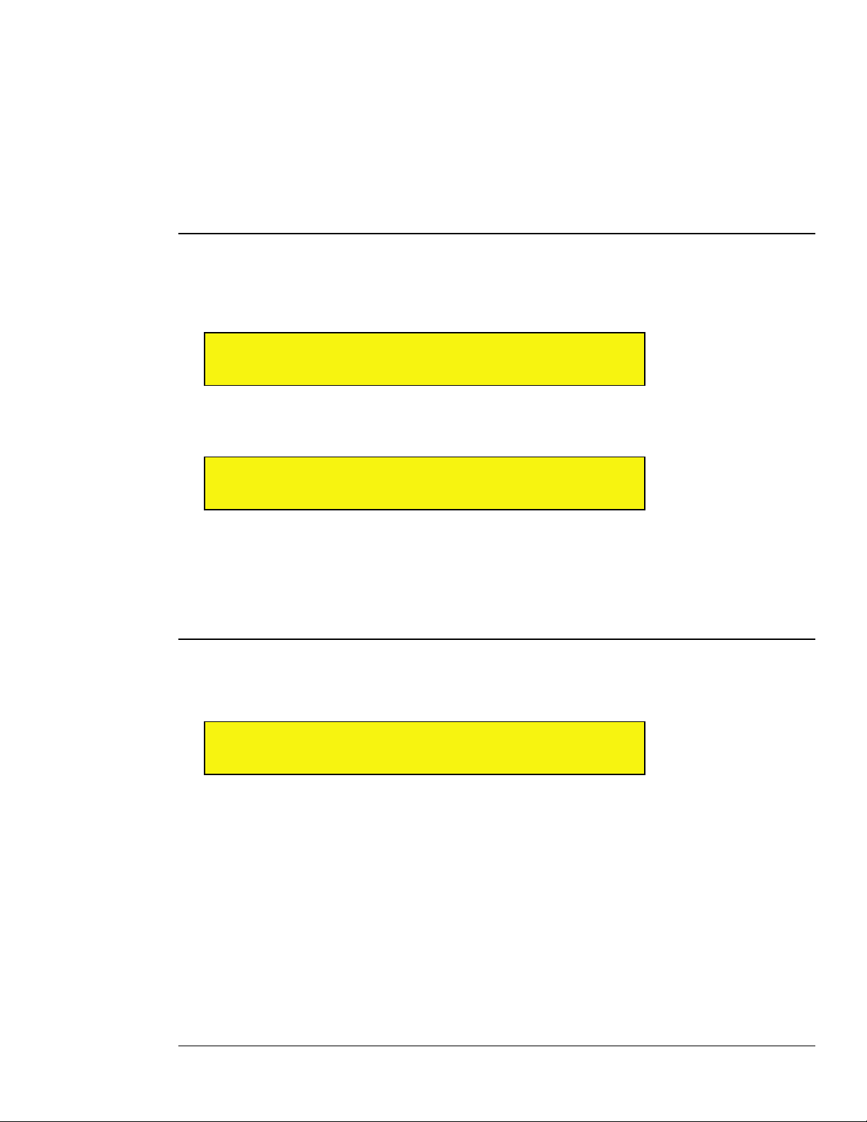
You can scroll through the various Source and FX plugin assignments to look for the problem. It will be easy to
spot, since the questionable plugin(s) will have a prefix before their name that indicates what the problem might
be. Specifically:
• [XX] before a plugin name means that it’s no longer on Receptor’s hard drive
• [--] before a plugin name means it’s a premium plugin whose demo period has expired. If you wish to use
this plugin, you must purchase a license for it from www.plugorama.com.
• [##] before a plugin name means the plugin has not yet had its demo period activated
• [??] before a plugin name indicates an error, most likely that the iLok is not inserted properly.
SINGLE: Load Blank Patch
Rotate the top display knob to select the Load Blank Patch parameter. This special patch resets your Single
by uninstantiating every plugin on that instrument channel and returning it to its default configuration. This is
the ideal way to “wipe the slate clean” and start setting up an instrument panel from scratch.
0 1 L o a d B l a n k P a t c h <
III III P r e s s k n o b t o l o a d
To initialize the Instrument Channel, simply press the bottom display knob. The channel will be cleared and the
screen will indicate when the process is finished.
0 1 L o a d B l a n k P a t c h <
III III L o a d e d
SOURCE Button
This section discusses the parameters available when you press the SOURCE button on Receptor.
SOURCE: View Plugin Type
Use the View Plugin Type parameter to filter the list of plugins displayed by the SOURCE: Plugin parameter
described in the next section.
0 1 V i e w P l u g i n T y p e >
III III A l l
Rotate the bottom display knob to select what type of plugins you want to display in the SOURCE: Plugin page.
You do not need to press the bottom display knob to apply your choice -- it happens automatically.
You can select the following View filters:
• All -- Select this option to display alphabetically every plugin on the SOURCE: Plugin page.
• Audio Inputs -- Select this option to display only the list of Audio Inputs on the SOURCE: Plugin page.
• <Developer Name> -- Select the name of the plugin developer to display only those plugins made by that
particular developer on the SOURCE: Plugin page. For example, if you choose “reFX,” the SOURCE:
Plugin page would show only reFX products, like Beast, Claw, PlastiCZ, Slayer2, and Vanguard.
NOTE: Although this is the first SOURCE parameter page, it is not actually the screen you “land on” when you
press the SOURCE button. Pressing the SOURCE button lands you on the Plugin parameter screen (described
below).
5: View Buttons in Depth 45 Receptor Manual
Page 46

SOURCE: Source
This parameter works in conjunction with the View Plugin Type parameter described above. It lists every
possible audio source of the type you chose to view. If you chose All as the plugin type on the View Plugin
Type page (the default choice), then the Source parameter displays every possible audio source available for that
channel. An audio source can be either a VSTi (software plugin) or an external audio input (hardware plugin).
If you select a VSTi, Receptor instantiates that plugin. If you select an audio input, Receptor uses the signal
appearing at that input as the audio source.
0 1 S o u r c e < >
III III C o m b o S i s t e r
Rotate the bottom display knob to select the audio source. Sources appear in the list as follows:
• (none): This option always appears first. Selecting it uninstantiates a Source plugin. When you uninstantiate
a Source plugin, you automatically clear any FX instantiations used in the channel. Essentially, (none)
provides a shortcut for completely clearing an instrument channel.
• Audio Inputs: These always appear immediately after the (none) option.
• VSTi plugins: All VSTi plugins appear in alphabetical order. Some plugins may have a 2-character prefix
contained inside a square bracket. This prefix, described a bit later, does not alter the display order of
plugins.
The name flashes indicating you must press the bottom display knob to actually load the selected source plugin.
SHORTCUT: If you’ve chosen anything other than All on the View Plugin Type page, this plugin list will not
show every possible audio source built-in to Receptor. If you want to see ALL the plugins in this list, simply turn
the bottom display knob to the last choice, which is “View All Plugins” and press the bottom display knob. This
automatically sets the View Plugin Type to All without you having to select that page. Once you’ve done this,
all the audio sources will appear alphabetically in this list.
Source Prefixes
Some plugins may have bracketed prefixes before their names. Here’s what they mean:
• [##] - This means that a demo version of the plugin is currently installed and that, by instantiating it, you
will activate its demo period.
• [nn] - In this case, nn = some number, such as 17, or 03, or 11. This means that the plugin is currently
running in demo mode and this prefix shows you how many days remain in your demo period.
• [--] : This means that the installed plugin must be purchased in order to be instantiated. You will see this
symbol when a demo period has expired or if no demo is available for a particular plugin. Also, when you
turn on Receptor, your iLok is scanned for licenses after the unit starts up. Because of this, it’s possible that
plugins you have purchased will display the [--] prefix for the first couple of minutes. Don’t worry. Your
purchased premium plugins will still instantiate if selected. It just takes a couple of minutes for Receptor to
scan all the plugins and update their prefix display, which it does in the background so that Receptor will
start up as quickly as possible.
• [??] - This means that an error is preventing you from instantiating this plugin. In most cases, it appears
because the iLok is not inserted into Receptor properly.
• [XX] - This means that the plugin is no longer on Receptor’s hard drive. Obviously, this will only appear if
you have loaded a Single or Multi patch that references a plugin no longer on Receptor.
• No Prefix - If there is no prefix before a plugin name, that means it’s either a free plugin or a premium
plugin that you have purchased.
5: View Buttons in Depth 46 Receptor Manual
Page 47
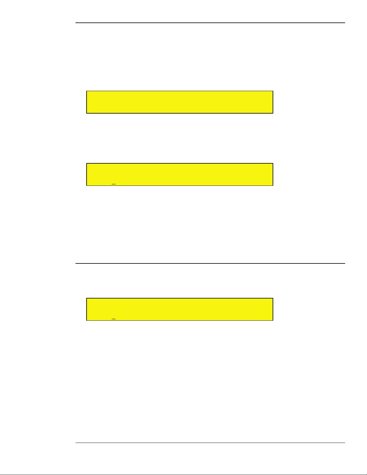
SOURCE: Bank
In order to conform with MIDI standards, patches are stored together in a group, which is called a ‘bank.’ Each
bank can hold up to 128 patches. Receptor can store over 16,000 banks of VST patches (for a maximum of over
2,000,000 VST patches). To select a patch from a particular bank, you must first select the bank, then the actual
patch.
To select a bank and load a patch from that bank:
1 Rotate the top display knob to select the Bank parameter.
0 1 B a n k < >
III III B a n k : S a n d y C l a w s
2 Rotate the bottom display knob to select the bank you wish to load.
The bank name is flashing
3 Press the bottom display knob.
Receptor shows you the first patch in that bank.
0 1 P a t c h < >
III III 0 0 1 : C r a z y B a s s
4 Rotate the bottom display knob to select a patch. The patch name will flash.
5 Press the bottom display knob to load that patch into Receptor.
NOTE 1: You cannot select a bank without also selecting a patch, since a Bank is nothing more than a directory
of patches.
NOTE 2: ROM bank names are enclosed in angle brackets, like <this>. When you see a bank name enclosed
in <angle brackets>, it means the bank is a “factory” bank and cannot be overwritten or deleted. For more
information, see “ROM Banks and RAM Banks” on page 127.
SOURCE: Patch
If you want to select a patch from the current bank, rotate the top display knob to select the Patch parameter. If
you want to select a patch from a different bank, it will be fastest to use the Bank parameter discussed above.
0 1 P a t c h < >
III III 0 0 1 : S y n c L e a d
Rotate the bottom display knob to select the patch you wish to load. The patch name is flashing, indicating you
must press the bottom display knob to actually load the selected patch.
If you’re currently viewing the last patch in a bank, and you turn the bottom display knob another notch
clockwise, Receptor will automatically switch to the next bank and display the first patch within that bank. The
same is true if you’re viewing the first patch in a bank and turn the bottom display knob counter-clockwise.
Essentially, you can scroll through every patch without using the Bank parameter at all! However, with over 2
million patch locations available, we’re quite certain that you’ll want to make use of the Bank parameter.
NOTE 1: Patches for some plugins, particularly those that must load samples from hard disk, may take longer
to load than others (such as simple algorithmic effect or synth patches).
NOTE 2: The Patch parameter does not appear if you select an audio input source for the Plugin parameter.
NOTE 3: ROM patch names are enclosed in angle brackets, like <this>. When you see a patch name enclosed
in <angle brackets>, it means the patch is a “factory” patch and cannot be overwritten or deleted. For more
information, see “ROM Banks and RAM Banks” on page 127.
5: View Buttons in Depth 47 Receptor Manual
Page 48
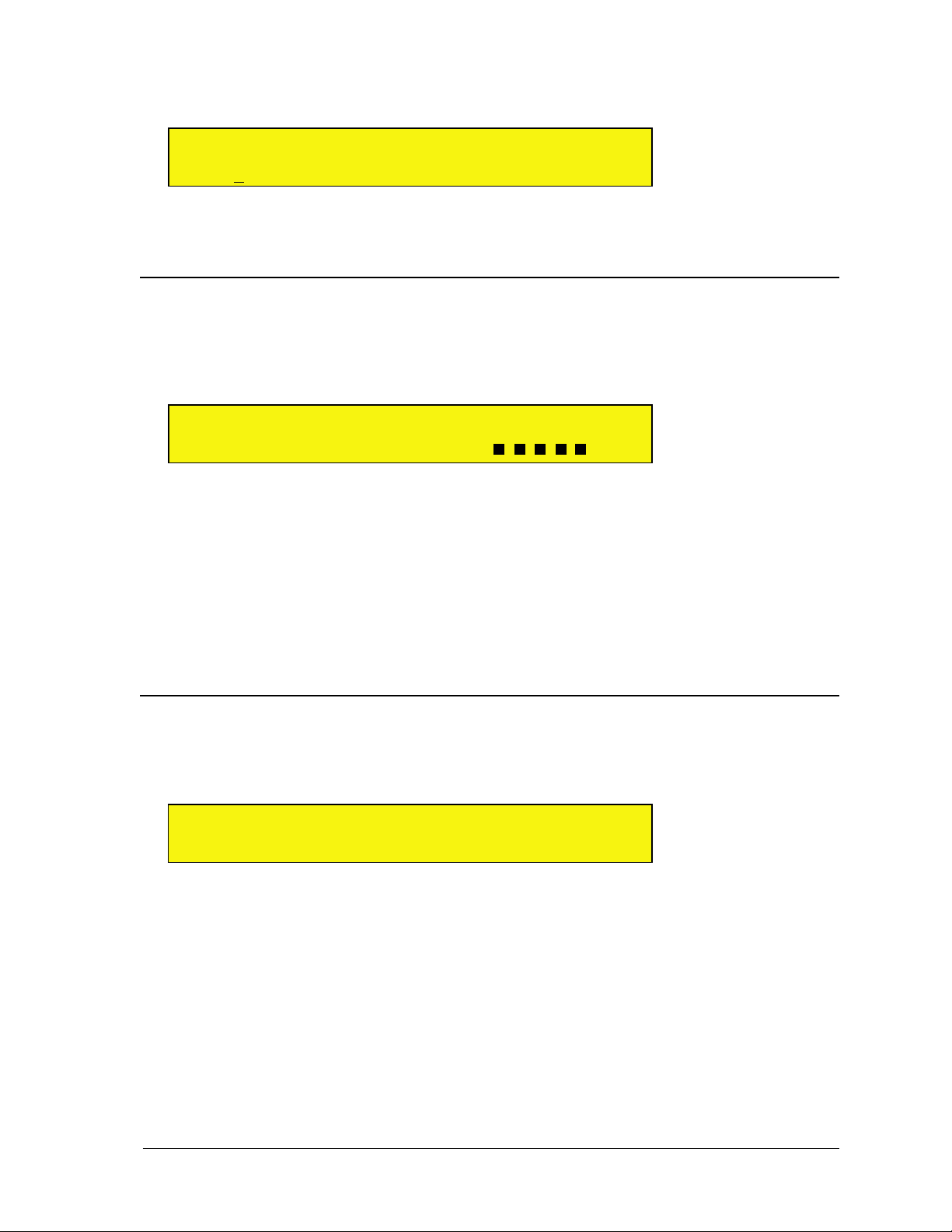
NOTE 4: If you have edited a patch in any way, an asterisk (*) replaces the colon (:) between the patch number
and name. When you see an asterisk between the patch number and name, you’ll know that the version currently
in the edit buffer is not what’s stored to disk.
0 1 P a t c h < >
III III 0 0 1 * S y n c L e a d
If you want to save your patch, press the SAVE /FILE button to save your edits (as described in “SAVE/FILE
Button” on page 75).
SOURCE: Input Gain
This parameter appears only if you set the Source parameter to “Line Input,” which is the rear panel analog
input. If you set the Source parameter to Line Input and rotate the top display knob, you’ll see the Input Gain
parameter. Use this parameter to monitor a summed signal level arriving at the rear analog inputs and adjust the
gain, if necessary.
0 1 I n p u t G a i n < >
III III + 0 3 . 0 d B L V L :
Rotate the bottom display knob to increase or decrease the amount of gain you wish to apply to the rear panel
analog inputs. The gain affects both the left and right channels equally. You can boost the rear panel audio input
gain as much as 18 dB. The gain change happens instantly, meaning you’re not required to push the bottom
display knob to apply the change.
The bottom right corner of the LCD contains an 8-stage rear analog input level meter. You will want to adjust
the Input Gain so that this signal is as high as possible without clipping. Clipping is indicated by an exclamation
point.
NOTE: If you wish to see both the left and right side levels of the rear analog input, you may press the METERS
button while the SOURCE button is lit. For more information, see “Meters Mode” on page 82.
SOURCE: Bypass
Rotate the top display knob to select the Bypass parameter. Bypassing a source mutes it and releases the CPU
resources required to run it. Bypass is useful whenever Receptor’s CPU resources are maxed out and you want
to disable a particular plugin.
0 1 B y p a s s < >
III III N o t B y p a s s e d
Rotate the bottom display knob clockwise to select Bypassed. Rotate the bottom display knob counterclockwise to select Not Bypassed. The change happens instantly, meaning you’re not required to push the
bottom display knob to apply the change.
SHORTCUT: Pressing the bottom display knob toggles between Bypassed and Not Bypassed.
NOTE: If you bypass a source that uses one of the audio inputs (rather than a VSTi), then the audio input is
muted, but no significant amount of CPU resources are saved.
5: View Buttons in Depth 48 Receptor Manual
Page 49
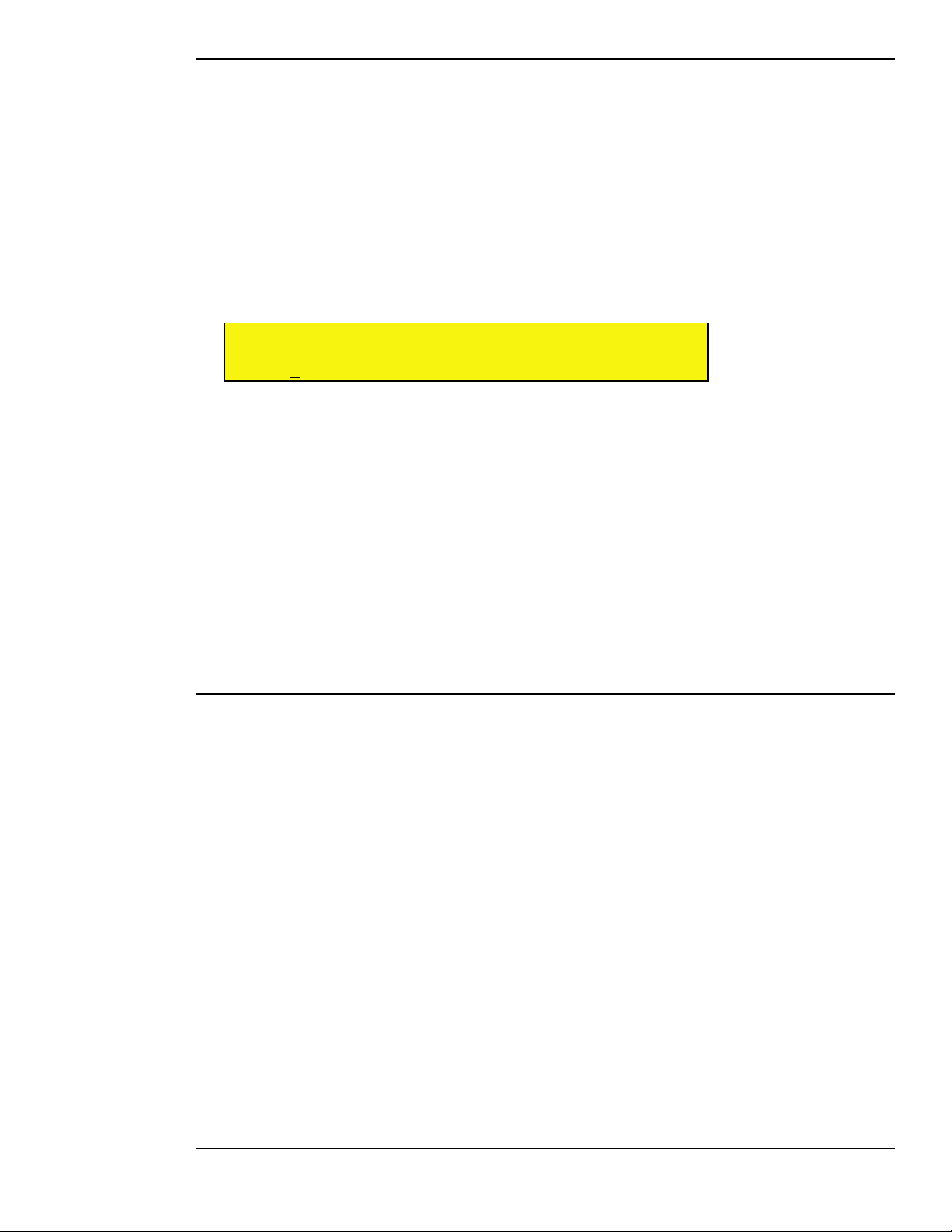
SOURCE: Listen to MIDI Ch
Rotate the top display knob to select the Listen to MIDI Ch parameter. Use this parameter to tell the
selected VSTi which incoming MIDI channel to “listen” to. By default, the VSTi plugin you instantiate on each
Instrument Channel responds to the like-numbered MIDI Channel. For example, the VSTi you instantiate on
Instrument Channel 6 would respond to data coming in on MIDI channel 6. In general, you will only change
this default mapping when you want to stack or split two or more VSTi’s on the same MIDI channel.
For example, you might want to instantiate an analog synth on Instrument Ch 1 and a string synthesizer on
Instrument Ch 2, but play them simultaneously from your keyboard to create a thicker, richer sound. To do this,
you would set the source on Instrument Channel 2 to respond to MIDI Ch 1. Now, when you play your MIDI
keyboard using MIDI Ch 1, Receptor plays both the VSTi assigned to Instrument Ch 1 and the one assigned to
Instrument Ch 2. The same technique can be used in conjunction with the Note Range and Velocity Range
parameters (discussed later) to create keyboard splits and zones.
0 1 L i s t e n t o M I D I C h < >
III III 0 1
Rotate the bottom display knob to select which incoming MIDI channel the VSTi should listen to. The Channel
number is underlined, but does not flash. When you select a different channel, the change is instantly applied.
You can choose between MIDI channels 1-16, or you can choose All, which means that the VSTi responds to
data coming from any and all MIDI channels.
For more details and examples of this parameter’s use, see “Source: MIDI Filter Button” on page 97.
NOTE 1: This parameter only changes the MIDI channel used to control the sound being produced by an
instantiated VSTi. It does not re-channelize the data used to control the Instrument Channel (such as Volume,
Pan, Effects Send Levels, and so on). For example, if you instantiated a VSTi on Instrument Channel 2, but
told it to listen to MIDI Ch 1, the VSTi would respond to note, pitch bend, mod, and sustain pedal data on MIDI
channel 1, but the Instrument Channel’s volume, pan, effects send levels, and so on would still respond to MIDI
channel 2. This allows you to separately address and mix Receptor’s 16 instrument channels, even though some
of them may use layered instruments.
NOTE 2: This parameter does not appear if you select an audio input source for the Plugin parameter.
SOURCE: Plugin MIDI Ch
Rotate the top display knob to select the Plugin MIDI Ch parameter. Use this parameter when a plugin needs to
play on a particular MIDI channel regardless of what MIDI channel is used to trigger it.
By default, this parameter is always set to 01, meaning every instantiated instrument plays whatever sound
is assigned to it’s internal definition of channel 1. In general, you will not need to change this default MIDI
channel mapping since the majority of VSTi’s are monotimbral and will respond the same no matter which
MIDI channel you use to play them.
A small number of VST instruments (such as Native Instruments’ B4) respond differently depending on which
MIDI channel you play them on. For example, B4’s upper manual is hardwired to MIDI Ch 1; its lower manual
to MIDI Ch 2; and its pedals to MIDI Ch 3. If, for example, you instantiated the B4 on Instrument Channel
7, you would hear its upper manual play (since all plugin channels are, by default, remapped to Ch 1). If you
actually wanted to play the lower manual, you would set the Plugin MIDI Ch value to 2 so that the incoming
MIDI data would be routed to B4 Channel 2, which is the lower organ manual.
In addition, some VST instruments are multitimbral and may therefore have different sounds assigned to
different MIDI channels. Most of these multitimbral instruments will work flawlessly with MIDI channel 1,
which is why this is the default value. However, the Plugin MIDI Ch parameter lets you control any plugin
channel you wish, regardless of which Instrument Channel you used to instantiate the plugin, or which
incoming MIDI Channel it listens to.
5: View Buttons in Depth 49 Receptor Manual
Page 50
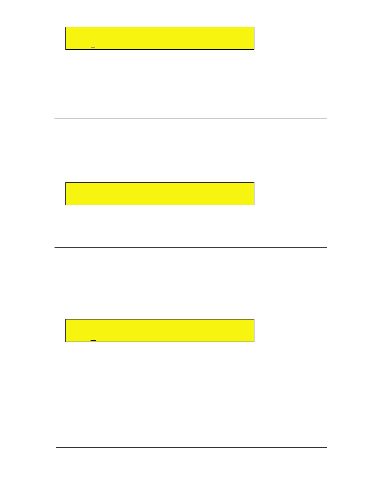
0 1 P l u g i n M I D I C h < >
III III 0 2
Rotate the bottom display knob to choose the channel remapping. The Remap channel is underlined but not
flashing. When you select a different channel, the change is instantly applied. You can choose between MIDI
channel 1-16, or you can choose “Thru”, which means that the VSTi plays on the same MIDI channel set by the
Listen to MIDI Ch parameter.
For more details and examples of this parameter’s use, see “Source: MIDI Filter Button” on page 97.
NOTE: This parameter does not appear if you select an audio input source for the Plugin parameter.
SOURCE: Channel Transpose
Rotate the top display knob to select the Channel Transpose parameter. Use Channel Transpose to transpose
the playback pitch of the instrument channel up or down 3 octaves, in semitone increments. Because Channel
Transpose acts only on the selected channel, it is different than the global, Receptor-wide transposition value
set by the Master Transpose parameter, which is available under the SETUP button. Channel Transpose is
particularly helpful when used in conjunction with the Note Range parameter, since it will let you “fit” the
desired octaves within the note range you select.
0 1 C h a n n e l T r a n s p o s e < >
III III - 1 2 S e m i t o n e s
Rotate the bottom display knob to set the Channel Transpose to any value between -36 semitones and +36
semitones. The change happens instantly, meaning you’re not required to push the bottom display knob to apply
the change.
SOURCE: Note Range
Rotate the top display knob to select the Note Range parameter. Use this parameter to limit the range of MIDI
notes to which the channel responds. The Note Range parameter is primarily used for setting up keyboard
split points on Receptor. For example, you might assign a bass synthesizer to Instrument CH 01 and a lead
synthesizer to Instrument CH 02. Then, for CH 01, you could set the Note Range value from C-1 to B3 and, for
CH 02, you could set its Note Range from C4 to G9. Now, any notes you play below middle-C will be played
by the bass synth assigned to CH 01 and any notes you play on middle-C or higher will be played by the lead
synth assigned to CH 02.
0 1 N o t e R a n g e < >
III III C - 1 t o G
The Note Range parameter actually contains two parameters: a From parameter (representing the lowest note
in the range) and a To parameter (representing the highest note in the range). Rotate the bottom display knob to
set the low note to the desired MIDI note, then press the bottom display knob to apply the selection. The cursor
moves under the To parameter. Rotate the bottom display knob to set the high note to the desired MIDI note,
then press the bottom display knob to apply the selection.
MIDI Input Shortcut: You can set note range values via a MIDI keyboard. Simply make sure the cursor is
under the note value you wish to change, then turn the bottom display knob. This puts Receptor into “listen”
mode. Play a note on your MIDI keyboard and Receptor will set the note to that value and stop listening. If you
want to set the note to a different value via MIDI, repeat the above procedure.
5: View Buttons in Depth 50 Receptor Manual
Page 51
SOURCE: Velocity Range
Rotate the top display knob to select the Velocity Range parameter. Use this parameter to limit the range of
MIDI velocity values to which the channel responds. The Velocity Range parameter is used to assign certain
instruments to limited velocity ranges. For example, you might have an instrument channel that contains a
plugin that plays a big cymbal crash sound. If you limit the velocity range of this channel to 120-127, then the
channel will play only when it receives MIDI velocity values of 120 or greater -- in other words, when you hit
your MIDI keyboard really hard, the crash cymbal will sound -- for all lower velocity values, the crash cymbal
will not sound.
0 1 V e l o c i t y R a n g e <
III III 0 t o 1 2 7
The Velocity Range parameter actually contains two parameters: a From parameter (representing the lowest
velocity in the range) and a To parameter (representing the highest velocity in the range). Rotate the bottom
display knob to set the low velocity to the desired value (0-127), then press the bottom display knob to apply the
selection. The cursor moves under the To parameter. Rotate the bottom display knob to set the high velocity to
the desired value (0-127), then press the bottom display knob to apply the selection.
MIDI Input Shortcut: You can set velocity range values via a MIDI keyboard. Simply make sure the cursor is
under the velocity value you wish to change, then turn the bottom display knob. This puts Receptor into “listen”
mode. Play a note on your MIDI keyboard and Receptor will set the velocity value to match and stop listening.
If you want to set the velocity to a different value via MIDI, repeat the above procedure.
FX A, FX B, FX C Buttons
Each of Receptor’s 16 instrument channels, 2 effects bus channels, and 1 master channel contains a set of three
insert effects, labeled FX A, FX B, and FX C. Parameter selection is identical for all three effects on all 19
channels and is thus only defined once in this section.
This section discusses the parameters available when you press the FX A, FX B, or FX C buttons on Receptor.
FX: View Plugin Type
Use the View Plugin Type parameter to filter the list of plugins displayed by the FX: Plugin parameter
described in the next section.
0 1 V i e w P l u g i n T y p e >
III III A l l
Rotate the bottom display knob to select what type of plugins you want to display in the FX: Plugin page. You
do not need to press the bottom display knob to apply your choice -- it happens automatically.
You can select the following View filters:
• All - Select this option to display alphabetically every plugin on the FX: Plugin page.
• <Developer Name> - Select the name of the plugin developer to display only those plugins made by that
particular developer on the FX: Plugin page. For example, if you chose “Ohmforce,” the FX: Plugin page
would show only Ohmforce plugins, such as Frohmage, Hematohm, Mobilohm, Ohmboyz, Predatohm, and
Quad Frohmage.
NOTE: Although this is the first FX parameter page, it is not actually the screen you “land on” when you press
the FX button. Pressing the FX button lands you on the Plugin parameter screen (described below).
5: View Buttons in Depth 51 Receptor Manual
Page 52
FX: Plugin
This parameter works in conjunction with the FX: View Plugin Type parameter described above. It lists
every plugin of the type you chose to view. If you chose “All” as the plugin type on the FX: View Plugin Type
page (the default choice), then the FX: Plugin parameter displays every available plugin for that channel.
0 1 P l u g i n < >
III III F r o h m a g e F i l t e r
Rotate the bottom display knob to select the desired effect plugin. Plugins are listed in alphabetical order. Some
plugins may have a 2-character prefix contained inside a square bracket. This prefix, described a bit later, does
not alter the display order of plugins. The plugin name flashes indicating you must press the bottom display
knob to actually load the selected plugin.
SHORTCUT: If you’ve chosen anything other than All on the FX: View Plugin Type page, this plugin list will
not show every possible audio source built-in to Receptor. If you want to see all the plugins in this list, simply
turn the bottom display knob to the last choice, which is “View All Plugins” and press the bottom display knob.
This automatically sets the FX: View Plugin Type to All without you having to select that page. Once you’ve
done this, all the FX plugins will appear alphabetically in this list.
Plugin Prefixes
Some plugins may have bracketed prefixes before their names. Here’s what they mean:
• [##] - This means that a demo version of the plugin is currently installed and that, by instantiating it, you
will activate its demo period.
• [nn] - In this case, nn = some number, such as 17, or 03, or 11. This means that the plugin is currently
running in demo mode and this prefix shows you how many days remain in your demo period.
• [--] - This means that the installed plugin must be purchased in order to be instantiated. You will see this
symbol when a demo period has expired or if no demo is available for a particular plugin. Also, when you
turn on Receptor, your iLok is scanned for licenses after the unit starts up. Because of this, it’s possible that
plugins you have purchased will display the [--] prefix for the first couple of minutes. Don’t worry. Your
purchased premium plugins will still instantiate if selected. It just takes a couple of minutes for Receptor to
scan all the plugins and update their prefix display, which it does in the background so that Receptor will
start up as quickly as possible.
• [??] - This means that an error is preventing you from instantiating this plugin. In most cases, it appears
because the iLok is not inserted into Receptor properly.
• [XX] - This means that the plugin is no longer on Receptor’s hard drive. Obviously, this will only appear if
you have loaded a Single or Multi patch that references a plugin no longer on Receptor.
• No Prefix - If there is no prefix before a plugin name, that means it’s either a free plugin or a premium
plugin that you have purchased.
FX: Bank
In order to conform with MIDI standards, patches are stored together in a group, which is called a ‘bank.’ Each
bank can hold up to 128 patches. Receptor can store over 16,000 banks of VST patches (for a maximum of over
2,000,000 VST patches). To select a patch from a particular bank, you must first select the bank, then the actual
patch.
To select a bank and load a patch from that bank:
1 Rotate the top display knob to select the Bank parameter.
0 1 B a n k < >
III III B a n k : F a v o r i t e F i l t e r s
5: View Buttons in Depth 52 Receptor Manual
Page 53
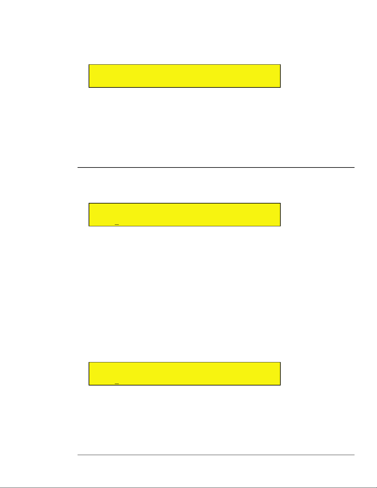
2 Rotate the bottom display knob to select the bank you wish to load.
The bank name is flashing
3 Press the bottom display knob.
Receptor shows you the first patch in that bank.
0 1 P a t c h < >
III III 0 0 1 : S o f t n F u z z y
4 Rotate the bottom display knob to select a patch. The patch name will flash.
5 Press the bottom display knob to load that patch into Receptor.
NOTE 1: You cannot select a bank without also selecting a patch, since a Bank is nothing more than a directory
of patches.
NOTE 2: ROM bank names are enclosed in angle brackets, like <this>. When you see a bank name enclosed
in <angle brackets>, it means the bank is a “factory” bank and cannot be overwritten or deleted. For more
information, see “ROM Banks and RAM Banks” on page 127.
FX: Patch
If you want to select a patch from the current bank, rotate the top display knob to select the Patch parameter. If
you want to select a patch from a different bank, it will be fastest to use the Bank parameter discussed above.
0 1 P a t c h < >
III III 0 0 1 : S o f t n F u z z y
Rotate the bottom display knob to select the patch you wish to load. The patch name is flashing, indicating you
must press the bottom display knob to actually load the selected patch.
If you’re currently viewing the last patch in a bank, and you turn the bottom display knob another notch
clockwise, Receptor will automatically switch to the next bank and display the first patch within that bank. The
same is true if you’re viewing the first patch in a bank and turn the bottom display knob counter-clockwise.
Essentially, you can scroll through every patch without using the Bank parameter at all! However, with over 2
million patch locations available, we’re quite certain that you’ll want to make use of the Bank parameter.
NOTE 1: Patches for some plugins, particularly those that must load samples from hard disk or are very
complex, may take longer to load than others (such as simple algorithmic effect or synth patches).
NOTE 2: ROM patch names are enclosed in angle brackets, like <this>. When you see a patch name enclosed
in <angle brackets>, it means the patch is a “factory” patch and cannot be overwritten or deleted. For more
information, see “ROM Banks and RAM Banks” on page 127.
NOTE 3: If you have edited a patch in any way, an asterisk (*) replaces the colon (:) between the patch number
and name. When you see an asterisk between the patch number and name, you’ll know that the version currently
in the edit buffer is not what’s stored to disk.
0 1 P a t c h < >
III III 0 0 1 * S o f t n F u z z y
If you want to save your patch, press the SAVE /FILE button to save your edits (as described in “SAVE/FILE
Button” on page 75).
5: View Buttons in Depth 53 Receptor Manual
Page 54
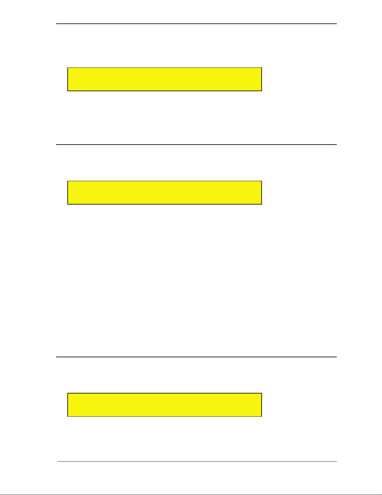
FX: Bypass
Rotate the top display knob to select the Bypass parameter. Bypassing an effect mutes it and releases the CPU
resources required to run it. Bypass is useful for comparing an effected sound to the un-effected sound. It’s also
useful whenever Receptor’s CPU resources are maxed out and you want to disable a particular plugin.
0 1 B y p a s s < >
III III N o t B y p a s s e d
Rotate the bottom display knob clockwise to select Not Bypassed. Rotate the bottom display knob counterclockwise to select Bypassed. The change happens instantly, meaning you’re not required to push the bottom
display knob to apply the change.
SHORTCUT: Pressing the bottom display knob toggles between Bypassed and Not Bypassed.
FX: Route
Rotate the top display knob to select the Route parameter. Use the Route parameter to change the configuration
of the three insert effects.
0 1 R o u t e < >
III III A > B > C
There are four options:
• A > B > C - This is the default routing. It’s a series connection in which the output of FX A feeds the
input of FX B, whose output feeds the input of FX C. It’s the mode used by nearly every mixing console
and is the most familiar to musicians. If your effect chain isn’t giving you the results you expect, you’re
probably not using the A > B > C effect routing. If an effect is unassigned, it is simply short-circuited.
• A / B / C - This is a parallel routing, in which FX A, B, and C receive dry feeds and process them
independently. This can drastically alter the sound of the effects chain. Note that, unlike a series connection,
unassigned parallel effects are open-circuited so they do not pass unfiltered signal to the output of the chain.
• A / B > C - This is a combination series/parallel routing in which the signal is split before being sent to
FX A and FX B. The output of FX B runs into the input of FX C, and the output of FX C is then combined
with FX A. Again, this can substantially alter the sound of the effects chain.
• A > B / C - This is a combination series/parallel routing in which the signal is split before being sent to
FX A and FX C. The output of FX A runs into the input of FX B, and the output of FX B is then combined
with FX C. Again, this can alter the sound of the effects chain. Feel free to experiment.
Rotate the bottom display knob to choose between the four effect routings. The routing flashes indicating you
must press the bottom display knob to actually load the effect routing.
FX: Switch
Rotate the top display knob to select the Switch parameter. Use the Switch parameter to change the order of the
three insert effects.
0 1 S w i t c h < >
III III S w i t c h A & B
There are three options:
• Switch A & B - Switches the plugin and patch assigned to FX A with the one assigned to FX B.
• Switch A & C - Switches the plugin and patch assigned to FX A with the one assigned to FX C.
5: View Buttons in Depth 54 Receptor Manual
Page 55
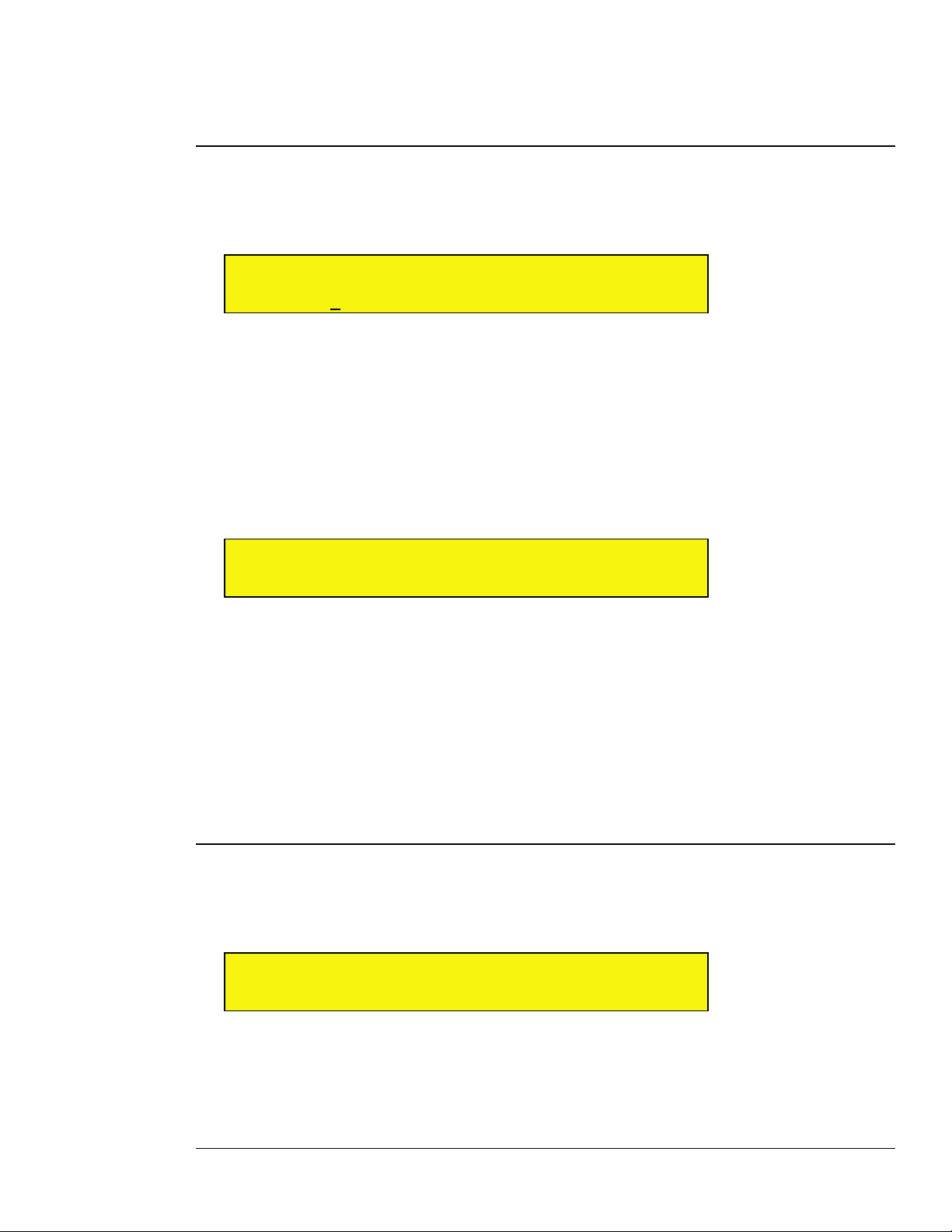
• Switch B & C - Switches the plugin and patch assigned to FX B with the one assigned to FX C.
Rotate the bottom display knob to choose between the three switch options. The switch option flashes indicating
you must press the bottom display knob to actually force the switch to occur.
FX: Get From
Rotate the top display knob to select the Get From parameter. Use the Get From parameter to copy the effect
(both the plugin and its current settings) from any other Receptor effects slot to the currently selected effects
slot.
0 1 G e t F r o m <
III III C H 0 2 : F X B : M u - P h a s e r
The Get From parameter takes the following form:
Ch <n>: FX <x >: <plugin name>
When you first select the Get From parameter, the Ch <n> field will be underlined and flashing. Rotate the
bottom display knob to select which Receptor channel contains the effect you wish to copy from (1-16, S1, S2,
or M), then press the bottom display knob to apply the selection, causing the FX<x> field to be underlined and
flashing. Select which effect (FX A, FX B, or FX C) you wish to get from that channel. As you do this, the name
of the plugin currently assigned to that slot will be shown in the display. The FX<x> value will flash until you
press the lower display knob, confirming that you’ve selected the plugin you wish to get.
The display will then ask you to confirm the copy operation.
By default, the display shows Yes. Rotate the bottom display knob counter-clockwise to select No. Your choice
will flash until you press the bottom display knob to apply it.
MIX Button
Each of Receptor’s 16 instrument channels, 2 effects bus channels, and 1 master channel contains a set of
mix parameters that vary slightly depending on whether you’re viewing an instrument channel, an effects bus
channel, or the master channel.
This section discusses the parameters available when you press the MIX button on Receptor.
MIX: Volume
This parameter controls the channel’s volume. If Ch 1-16 is displayed, it controls the volume for the
corresponding instrument. If Effects Bus 1 (B1) or Effects Bus 2 (B2) is displayed, it controls the corresponding
effect return level. If Master is displayed, it control’s Receptor’s master overall signal level.
0 1 A r e y o u s u r e ? <
III III Y e s
0 1 V o l u m e >
III III 1 0 5
Rotate the bottom display knob to set the volume level. Volume changes happen instantly, meaning you’re not
required to push the bottom display knob to apply the change.
SHORTCUT: When the Volume parameter is visible, you can reset it to its default level by pressing the bottom
display knob. The default level is 0dB, which provides neither volume gain nor volume attenuation.
5: View Buttons in Depth 55 Receptor Manual
Page 56
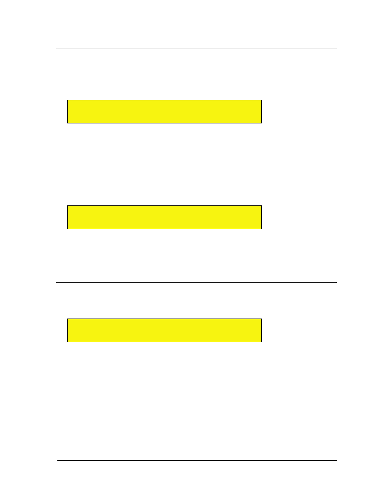
IMPORTANT: This is the output volume of the Receptor software -- it is not related to the Volume knob on
Receptor’s front panel, which is a hardware volume knob.
MIX: Pan
Rotate the top display knob to select the Pan parameter. All Receptor channels are stereo so, if an instantiated
plugin is actually mono, Receptor will double the signal such that the left and right channels are identical. In the
case of mono plugins, this parameter works like a traditional pan control. In the case of stereo plugins, it acts as
a balance control.
0 1 P a n < >
III III 1 7 L
Rotate the bottom display knob to set the pan level. Pan changes happen instantly, meaning you’re not required
to push the bottom display knob to apply the change.
SHORTCUT: When the Pan parameter is visible, you can reset the Pan to its center position by pressing the
bottom display knob.
MIX: Mute
Rotate the top display knob to select the Mute parameter. Muting a channel disables its output.
0 1 M u t e < >
III III N o t M u t e d
Rotate the bottom display knob clockwise to select Muted. Rotate the bottom display knob counter-clockwise to
select Not Muted. The change happens instantly, meaning you’re not required to push the bottom display knob
to apply the change.
SHORTCUT: Pressing the bottom display knob toggles between Muted and Not Muted.
MIX: Solo
Rotate the top display knob to select the Solo parameter. Soloing a channel automatically mutes all channels
that aren’t currently soloed, allowing you to isolate specific channels for editing.
0 1 S o l o < >
III III N o t S o l o e d
Rotate the bottom display knob clockwise to select Soloed. Rotate the bottom display knob counter-clockwise
to select Not Soloed. The change happens instantly, meaning you’re not required to push the bottom display
knob to apply the change.
SHORTCUT: Pressing the bottom display knob toggles between Soloed and Not Soloed.
5: View Buttons in Depth 56 Receptor Manual
Page 57
MIX: Send 1 Level
Rotate the top display knob to select the Send 1 Level parameter. This parameter controls how much of the
signal is sent to Effects Bus 1 (whose effect chain is configured in the B1 channel).
0 1 S e n d 1 L e v e l < >
III III 6 4
Rotate the bottom knob to set the level (0-127). Send levels change instantly, meaning you’re not required to
push the bottom display knob to apply the change.
SHORTCUT: When the Send 1 Level parameter is visible, you can press the bottom display knob to quickly set
it to zero.
MIX: Send 1 Pre/Post
Rotate the top display knob to select the Send 1 Pre/Post parameter. This parameter determines whether
the signal is routed to the effects bus before (pre) or after (post) going through the channel volume. If the signal
is Post Fader, then changing the Volume level changes the amount of effected signal proportionately. If the
signal is Pre Fader, then the Send Level and Volume levels act independently. This is useful if, for example,
you wish to hear only an effected signal with no dry signal, which you would accomplish by setting this
parameter to Pre Fader and the Volume level to zero.
0 1 S e n d 1 P r e / P o s t < >
III III P o s t F a d e r
Rotate the bottom display knob clockwise to select Pre Fader. Rotate the bottom display knob counterclockwise to select Post Fader. The change happens instantly, meaning you’re not required to push the
bottom display knob to apply the change.
SHORTCUT: Pressing the bottom display knob toggles between Pre and Post Fader.
MIX: Send 2 Level
Rotate the top display knob to select the Send 2 Level parameter. This parameter controls how much of the
signal is sent to Effects Bus 2 (whose effect chain is configured in the B2 channel).
0 1 S e n d 2 L e v e l < >
III III 5 1
Rotate the bottom knob to set the level (0-127). Send levels change instantly, meaning you’re not required to
push the bottom display knob to apply the change.
SHORTCUT: When the Send 2 Level parameter is visible, you can press the bottom display knob to quickly set
it to zero.
MIX: Send 2 Pre/Post
Rotate the top display knob to select the Send 2 Pre/Post parameter. This parameter determines whether
the signal is routed to the effects bus before (pre) or after (post) going through the channel volume. If the signal
is Post Fader, then changing the Volume level changes the amount of effected signal proportionately. If the
5: View Buttons in Depth 57 Receptor Manual
Page 58
signal is Pre Fader, then the Send Level and Volume levels act independently. This is useful if, for example,
you wish to hear only an effected signal with no dry signal, which you would accomplish by setting this
parameter to Pre Fader and the Volume level to zero.
0 1 S e n d 1 P r e / P o s t < >
III III P o s t F a d e r
Rotate the bottom display knob clockwise to select Pre Fader. Rotate the bottom display knob counter-clockwise
to select Post Fader. The change happens instantly, meaning you’re not required to push the bottom display
knob to apply the change.
SHORTCUT: Pressing the bottom display knob toggles between Pre and Post Fader.
MIX: Output Assignment
Rotate the top display knob to select the Output Assignment parameter. Use this parameter to route the
channel to a particular hardware output or (for Channels 1-16, and Effects Bus 1 and 2) to the Master channel
bus.
0 1 O u t p u t A s s i g n m e n t <
III III M s t r : Y A n l g : N S P D I F : Y
The Output Assignment parameter actually contains multiple options spread across multiple pages. On the first
page are the following output assignment options:
• Mstr (Master bus assignment): Y (Yes) or N (No)
• Anlg (Analog L-R output): Y (Yes) or N (No)
• SPDIF (S/PDIF L-R output): Y (Yes) or N (No)
On the second page are the next output assignment options:
• AD12 (ADAT 1-2 output): Y (Yes) or N (No)
• 34 (ADAT 3-4 output): Y (Yes) or N (No)
• 56 (ADAT 5-6 output): Y (Yes) or N (No)
• 78 (ADAT 7-8 output): Y (Yes) or N (No)
When you first choose the Output Assignment parameter, the Mstr option is underlined and active. Rotate the
bottom display knob to turn the output on (Y) or off (N), then press the bottom display knob to apply your
selection. The cursor moves under the Anlg option. Rotate the bottom display knob to turn it on or off, then
press the bottom display knob to apply the selection. The cursor moves under the SPDIF option. Select Y (on)
or N (off), then press the bottom display knob and the next output option (AD12) on page 2 is underlined and
ready for input. Continue rotating and pressing the bottom display knob until you’ve made all the desired output
assignments.
After you’ve made the final output assignment, you’ll see a screen asking whether or not you want to set the
Output Assignments to their default values. This gives you a quick way to reset the channel to Receptor’s
default output assignments.
0 1 O u t p u t A s s i g n m e n t <
III III S e t t o d e f a u l t ? N
Rotate the bottom display knob counter-clockwise to select N (no) or rotate it clockwise to select Y (yes), then
press the bottom display knob to apply your selection. The default output settings are as follows:
• Ch 1-16, B1, B2 -- Mstr:Y, Anlg:N, SPDIF:N, AD12:N, 34: N, 56:N, 78:N
• Master Channel -- Anlg:Y, SPDIF:Y, AD12:Y, 34:N, 56:N, 78:N
5: View Buttons in Depth 58 Receptor Manual
Page 59
You may route channels to as many outputs as you like. When you route a channel to the Master bus, it’s
output signal appears on the output(s) assigned to the Master Channel. When you route a channel directly to
a hardware output, its signal appears at that output, along with any other signals you may have routed to that
output. As you can tell, the Output Assignment option allows for very flexible routing and bussing, both on
stage and in the studio.
NOTE 1: The analog (Anlg) and ADAT 1-2 (AN12) outputs are duplicated on Receptor. So, if you turn one on
or off, the other will automatically turn on or off.
NOTE 2: The Mstr option is not available on the Master (M) channel since, obviously, you cannot assign the
output of a channel to itself. Also, Anlg and AD12 cannot be disabled for the Master (M) channel -- the Master
channel signal always appears at these two outputs.
SETUP Button
Setup parameters are used to make global changes to Receptor. Setup parameters affect such areas as global
tempo, transpose, and time signature settings; digital clock source and analog input level settings; and network
configuration settings.
SETUP: Channel Status
Rotate the top display knob to select the Channel Status screen. This screen shows you, at a glance, which
channels have instantiated plugins and if any channels are currently soloed or muted.
S U C h a n n e l S t a t u s >
III III 1 2 • • 5 • • • • • A • • • • • 1 • M
The bottom row of the LCD may appear a bit cryptic at first, but it’s really quite useful. Essentially, it contains
19 characters that, from left-to-right, display the status for each of Receptor’s 19 channels (first the 16
instrument channels, followed by the 2 effects busses, and finally the master output channel).
Specifically:
• If a channel has one or more plugins instantiated, its number is shown in the LCD (see “Channel Status
Numbering Guide” on page 60 to learn the numbering methodology).
• If a channel has no instantiated plugins, it’s indicated by a dot.
• If a channel is currently muted, a small letter “m” flashes alternated with the channel number.
• If a channel is currently soloed, a small letter “s” flashes alternated with the channel number.
Look at the following LCD screen as an example:
S U C h a n n e l S t a t u s >
III III 1 m • • 5 • • • • • A • • • • • 1 • M
This tells us that plugins are instantiated on instrument channels 1, 2, 5, 11 as well as on effects bus 1 and the
master output channel. Channel 2 is flashing the letter ‘m’, so we know that instrument channel 2 is currently
muted.
5: View Buttons in Depth 59 Receptor Manual
Page 60
Channel Status Numbering Guide
Are you wondering why, in the previous example, we know that channel 11 has plugins instantiated when the
display shows a letter “A”? That’s because double digit characters greater than 10 are represented by letters.
Specifically, here is how Receptor’s 19 mixer channels are represented, from left-to-right:
• 1-9 = Instrument Channels 1-9
• 0 = Ch 10
• A = Ch 11, B = Ch 12, C = Ch 13, D = Ch 14, E = Ch 15, F = Ch 16
• The “1” and “2” to the right of channel 16 (“F”) indicate the status of Effects Bus 1 and Effects Bus 2.
• The capital “M”, on the far right, indicates the Master channel.
SETUP: MIDI Monitor
Rotate the top display knob to select the MIDI Monitor screen. This screen shows you, at a glance, which
MIDI channels are currently receiving some type of MIDI message.
S U M I D I M o n i t o r < >
III III 1 2 • • • • • • 9 0 • B • • • F R
If signal is detected on an incoming MIDI channel, the display will show the channel’s number. If no signal
is detected on an incoming MIDI channel, the display will show a dot. This is a quick and convenient way to
troubleshoot your studio, as it allows you to verify whether or not MIDI is reaching Receptor, and on which
MIDI channel.
MIDI channel numbering appears in this view as follows:
• 1-9 = Instrument Channels 1-9
• 0 = Ch 10
• A = Ch 11, B = Ch 12, C = Ch 13, D = Ch 14, E = Ch 15, F = Ch 16
• R = Real-time (unchannelized MIDI messages)
For example, the sample display shown above tells you that MIDI data is currently being received on channels
1, 2, 9, 10, 12 and 16. The presence of the letter “R” also tells you that unchannelized real-time messages are
being sent to Receptor.
SETUP: Master Transpose
Rotate the top display knob to select the Master Transpose parameter.
S U M a s t e r T r a n s p o s e < >
III III N o T r a n s p o s e
Rotate the bottom display knob to transpose the MIDI note numbers by plus or minus 12 semitones. The
selection flashes indicating you must press the bottom display knob to apply the change. The Master Transpose
setting is saved with a Multi patch.
5: View Buttons in Depth 60 Receptor Manual
Page 61
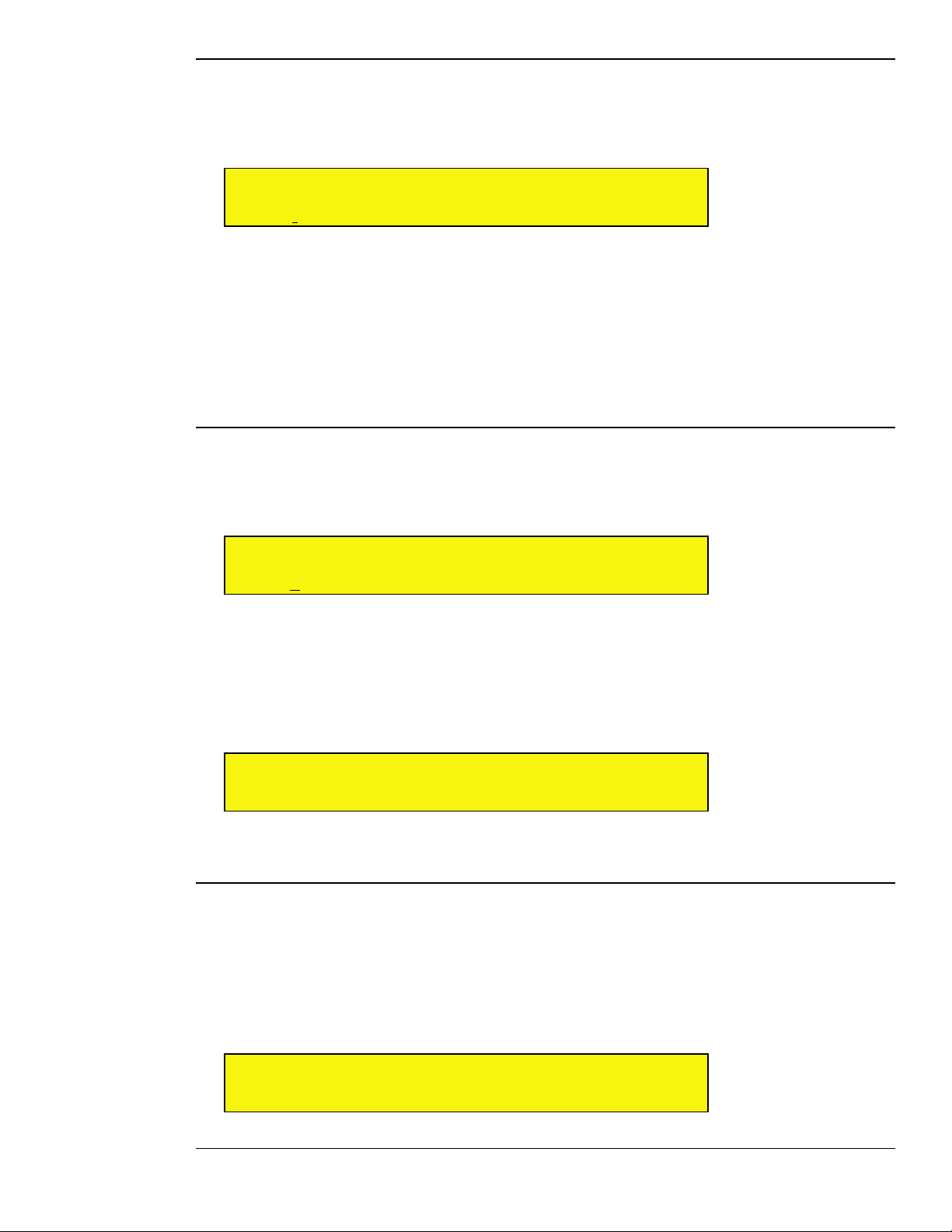
SETUP: Tempo Source
Rotate the top display knob to select the Tempo Source parameter. This determines whether Receptor derives
its tempo from external MIDI beat clock or whether it uses its own internal clock (set by the Tempo BPM
parameter). The Tempo Source is used by all tempo-based effects and instruments.
S U T e m p o S o u r c e < >
III III I n t e r n a l
Rotate the bottom display knob to select between External (MIDI) and Internal. Your selection is
immediately applied -- you do not need to push the bottom display knob.
• If you select External (MIDI), Receptor gets its tempo from an external MIDI beat clock (such as a
sequencer) arriving at its MIDI In port. It displays that tempo on the Setup: Tempo BPM page (discussed
next), using the most recently received tempo if none is currently present at the midi input.
• If you select Internal, Receptor gets its tempo from the Tempo BPM parameter (discussed next).
The Tempo Source setting is a global parameter that applies to all patches.
SETUP: Tempo BPM
Rotate the top display knob to select the Tempo BPM parameter. If you set the Tempo Source parameter to
Internal (as discussed in the previous section), then this value determines the internal tempo in Beats Per
Minute. This tempo is used by all tempo-based effects and instruments.
S U T e m p o B P M < >
III III 1 1 0
Rotate the bottom display knob to set Receptor’s internal tempo. Tempo changes happen instantly, meaning
you’re not required to push the bottom display knob to apply the change.
If the Tempo Source parameter is set to External (MIDI), then the Tempo BPM value is displayed, but can
not be edited. If you change the tempo of the external MIDI Beat Clock, you will see the tempo change in this
window. If no MIDI Beat Clock signal is currently present, the Tempo BPM displays the most recently received
MIDI tempo.
S U T e m p o B P M < >
III III 1 4 0 ( E x t e r n a l )
The Tempo BPM setting is a global parameter that applies to all patches.
SETUP: Time Signature
Rotate the top display knob to select the Time Signature parameter. Some plugins respond to time signature
but many do not.
In general, you should set Receptor’s time signature to match the time signature of your song. Note that
changing the time signature’s denominator always has an affect on tempo. For example, if you set the Tempo
BPM to 100 at 4/4 time, then change the Time Signature to 4/8 time, the tempo will double is speed (since
you have changed the definition of a ‘beat’ from a quarter-note to an eighth-note).
S U T i m e S i g n a t u r e < >
III III 4 / 4
5: View Buttons in Depth 61 Receptor Manual
Page 62
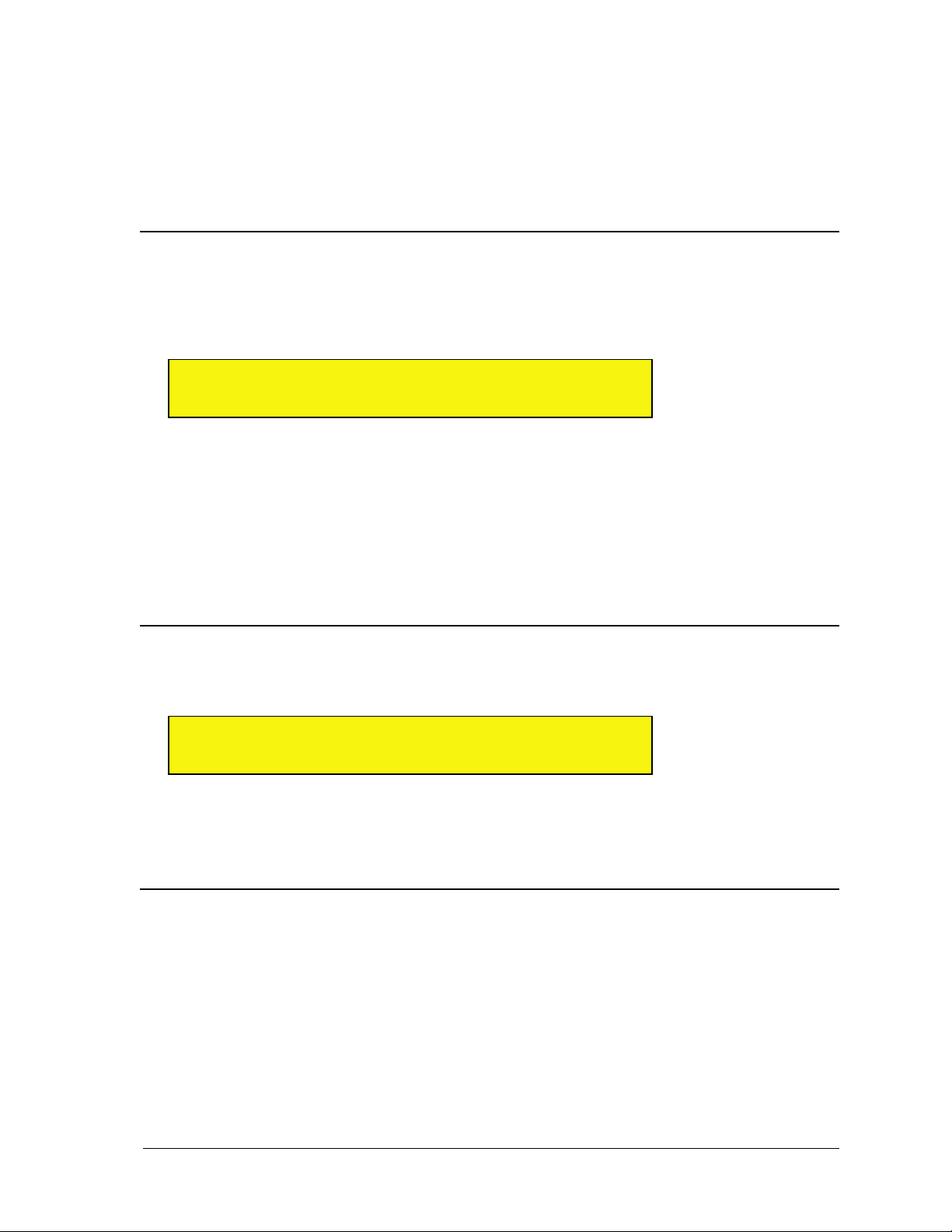
Rotate the bottom display knob to set Receptor’s time signature. The selection flashes indicating you must press
the bottom display knob to apply the change. Time signature values start at the lowest denominator and run
to the highest. So, if you set the time signature to its ‘minimum’ value, it will display 2/2. If you set it to its
‘maximum’ value, it will display 12/16.
Basically, rotating the lower knob takes you through time signature values as follows:
2/2 > 3/2 > ... 12/2 > 2/4 > 3/4 > ... 12/ 4 > 2/8 > 3/8 ... 12/8 > 2/16 > 3/16 > ... 12/16
The default time signature is 4/4 and the Time Signature value is saved globally.
SETUP: Program Change Chan
Use this parameter to tell Receptor which MIDI channel to use for incoming program changes. You can choose
to have Receptor listen to all channels; or any one of the available 16 MIDI channels; or no channel. This
parameter is, by default, set to ALL, meaning Receptor will respond to program changes received on all 16
MIDI channels.
S U P r o g r a m C h a n g e C h a n < >
III III A l l
When you limit the reception of program change messages to a single MIDI channel, Receptor will respond
only to program change message that are received on that channel. So, for instance, if this parameter is set to
Channel 03, then you will only be able to select plugin and Single patches assigned to channel 03, and your
Multi patches will only change when the message arrives on MIDI channel 03.
The primary reason for setting this parameter to something other than ALL is when Receptor is part of a multiunit rig and you’re using a master controller to send MIDI Program change messages to all your devices. In this
case, you may want to set Receptor to respond to a single MIDI channel so that it ignores any program change
messages intended for other devices.
SETUP: Digtl Clock Source
Rotate the top display knob to select the Digtl Clock Source parameter. Use this parameter to tell Receptor
whether to use its own internal digital clock or slave to an incoming SPDIF clock (if present).
S U D i g t l C l o c k S o u r c e < >
III III I n t e r n a l
Rotate the bottom display knob to choose between Internal and S/PDIF. The change happens instantly,
meaning you’re not required to push the bottom display knob to apply it.
The Digtl Clock Source is a global setting and, as such, is not stored with any patch.
SETUP: Master Sample Rate
Use this parameter to set Receptor’s default master clock rate. You can select between the following rates:
• 44.1 kHz
• 48 kHz
• 96 kHz
5: View Buttons in Depth 62 Receptor Manual
Page 63
Receptor defaults to 44.1 kHz, which is the standard “CD quality” sample rate. Choosing higher rates may result
in slightly better fidelity, but will make greater demands on Receptor’s CPU, resulting in fewer simultaneous
plugins and reduced polyphony. Also, be aware that not all plugins are designed to operate properly at higher
rates.
S U M a s t e r S a m p l e R a t e < >
III III 4 4 . 1 k H z
Rotate the bottom display knob to select the desired sample rate. The selection flashes indicating you must press
the bottom display knob to apply the change. The Master Sample Rate is a global setting and, as such, is not
stored with any patch
SETUP: Sample Buffer Size
Rotate the top display knob to select the Sample Buffer Size parameter. Selecting a smaller buffer size will
result in very low latencies, meaning Receptor will be extremely responsive to your playing. The trade-off is
that you will be able to instantiate fewer plugins. If you want to instantiate more plugins, or some particularly
CPU-intensive plugins, you will need to set the buffer size to a higher value.
S U S a m p l e B u f f e r S i z e < >
III III 1 2 8 S a m p l e s
Rotate the bottom display knob to choose the desired buffer size. The selection flashes, indicating you must
press the bottom display knob to apply the change.
The Sample Buffer Size is a global setting and, as such, is not stored with any patch.
SETUP: View Bank MSB/LSB
Rotate the top display knob to select the View Bank MSB/LSB parameter. This gives you a convenient way to
view the MSB/LSB MIDI Bank Select message values for any bank in Receptor.
S U V i e w B a n k M S B / L S B < >
III III M u l t i
Rotate the bottom display knob to select the patch type whose MIDI Bank Select messages you wish to change.
“Multi” is the first choice, followed by “Single.” Then, as you continue to rotate the bottom display knob, you’ll
see the name of each Receptor plugin in alphabetical order.
S U V i e w B a n k M S B / L S B < >
III III L o u n g e L i z a r d
The selection name is flashing, indicating you must press the bottom display knob to apply it. Select the type
of bank whose MSB/LSB numbering you wish to see, then press the bottom display knob. Rotate the bottom
display knob to select the bank whose MIDI Bank Select numbers you wish to view.
S U V i e w B a n k M S B / L S B < >
III III B a n k : W u r l i s
5: View Buttons in Depth 63 Receptor Manual
Page 64
The bank’s name is flashing, indicating you must press the bottom display knob to apply the selection. Select a
bank and press the bottom display knob.
S U V i e w B a n k M S B / L S B < >
III III 0 2 4 / 0 0 3 ( m o r e b a n k s )
The bank’s MSB and LSB numbers are displayed. These are the numbers you would enter in your MIDI
sequencer or MIDI control surface to select this bank via MIDI program change.
In addition, the (more banks) text will be flashing. If you press the lower display knob, you return to the
Bank Type screen where you can select other banks for which you wish to view the MSB/LSB assignments.
S U V i e w B a n k M S B / L S B < >
III III L o u n g e L i z a r d
SETUP: TCP/IP Setup
Rotate the top display knob to select the TCP/IP Setup parameter. Use this parameter if you want to switch
between manual or automatic IP addressing, or if you plan to use a crossover network. This is a multi-step
parameter, since changing TCP/IP setups requires setting multiple parameters.
S U T C P / I P S e t u p < >
III III A u t o ( D H C P )
Rotate the lower display knob to select between three choices: Auto (DHCP); Manual; and Crossover. These
are described further in the following sections.
NOTE: TCP/IP Setup is a global parameter and is not saved with a Multi Patch.
Using Auto (DHCP) Addressing
This is the default option. Select it if you are connecting Receptor to a network that has a cable/DSL modem
or Ethernet Switcher that acts as a DHCP server. Most such devices are configured to provide IP addresses to
network devices.
To use “Auto (DHCP)” addressing:
1 Rotate the bottom display knob to select Auto (DHCP), then press the knob to apply your selection.
You’ll be asked to confirm whether you want to make this change (Yes or No).
2 Rotate the bottom display knob to select Yes, then press the knob to apply your selection.
Receptor will update your TCP/IP settings — a process that will take a few seconds.
3 If you are switching to Auto (DHCP) from either Manual or Crossover modes, you must shut down your
Receptor and restart it before the settings take effect.
Receptor will now use an IP Address provided by a DHCP server. To see this address, rotate the top display
knob until the top line displays TCP/IP Address. The bottom line will then show the IP address used by
Receptor.
For more information about networking setups and Receptor, see Chapter 12, “Connecting Receptor to a
Computer.”
Using Manual IP Addressing
Select this option if you want to manually assign an IP address to Receptor. To do so:
1 Rotate the bottom display knob to select Manual, then press the knob to apply your selection.
You’ll next be asked to enter the desired IP Address. The IP Address is displayed in 4-blocks of 3-digit numbers. The
cursor is under the left-most block and the text is blinking.
5: View Buttons in Depth 64 Receptor Manual
Page 65
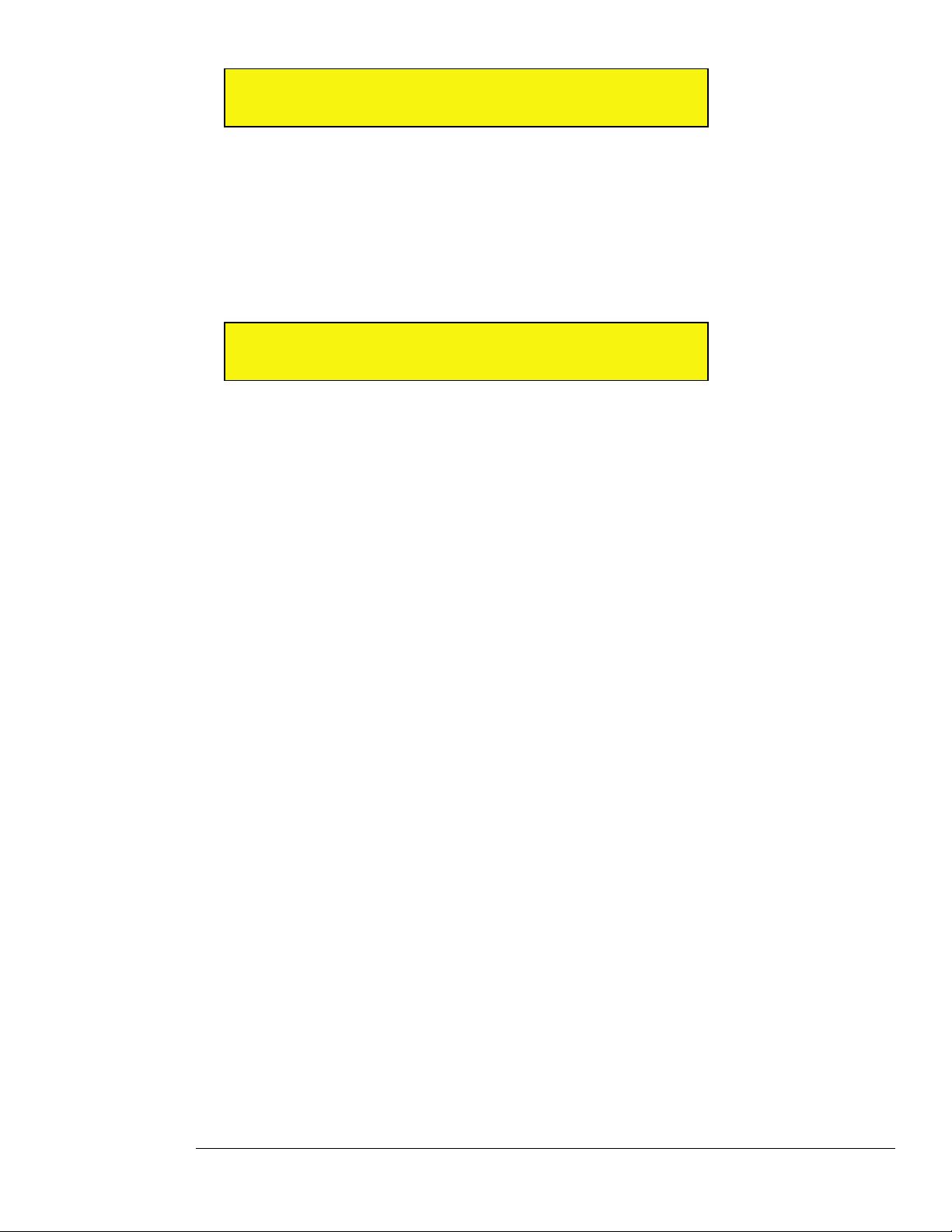
S U T C P / I P A d d r e s s < >
III III 1 9 2 . 1 6 8 . 0 0 1 . 0 7 5
2 Rotate the bottom display knob to select the desired value (from 000-255), then press the bottom display
knob.
The cursor moves to the next block of numbers, which are flashing.
3 Select the desired value for this block (from 000-255), then press the bottom display knob.
4 Continue until you’ve entered the desired IP address in all four blocks.
5 Press the bottom display knob after entering the fourth number block.
You’ll then be asked to enter the desired TCP/IP Netmask.
S U T C P / I P N e t m a s k < >
III III 2 5 5 . 2 5 5 . 2 5 5 . 0 0 0
6 Enter the netmask using the same technique used for entering the IP address, then press the bottom
display knob when finished.
You’ll then be asked to confirm your selection (Yes or No).
7 Rotate the bottom display knob to select Yes, then press the knob to apply your selection.
Receptor will update your TCP/IP settings — a process that will take a few seconds.
Receptor will now use the IP Address that you just entered manually. To see this address at any time, simply
rotate the top display knob until it displays TCP/IP Address. The bottom line will then show the IP address
used by Receptor.
For more information about networking setups and Receptor, see Chapter 12, “Connecting Receptor to a
Computer.”
Using Crossover Mode
Select this option if you are not using a Router or Switcher and are connecting Receptor directly to your
computer using a crossover Ethernet cable. To select and use Crossover Mode:
1 Connect a Crossover Ethernet Cable between your computer and Receptor.
2 If Receptor is not already in “Crossover” mode, put your Receptor into that mode by rotating the bottom
display knob to select Crossover, then press the bottom display knob to apply your selection.
You’ll be asked to confirm whether you want to make this change (Yes or No).
3 Rotate the bottom display knob to select Yes, then press the knob to apply your selection.
4 Before the switch to Crossover mode can take effect, you must turn off your PC and double-click
Receptor’s power button to turn it off.
5 Turn Receptor and your computer back on.
Receptor will now act as a DHCP server and provide an IP address to your PC.
WARNING: Never use Crossover Mode if Receptor is connected to a standard network. Most networks have
DHCP servers of their own. When Receptor is in Crossover mode, it is acting as a DHCP server, and the
presence of two such servers could confuse the network.
NOTE TO MACINTOSH USERS: If you’re using a Macintosh computer, crossover connections will work
without setting Receptor to Crossover Mode. If you frequently move your Receptor between a Macintosh
location that requires a network connection and one that requires a crossover connection, it’s alright to
leave Receptor in “Auto (DHCP)” mode. If, however, you plan to always use your Receptor with a crossover
connection to a Macintosh, you should set Receptor to “Crossover” mode to speed up the startup process.
Windows users must ALWAYS use Crossover Mode when using a crossover connection.
For more information about Crossover Mode and Crossover connections, see “Crossover Connection” on page
145.
5: View Buttons in Depth 65 Receptor Manual
Page 66
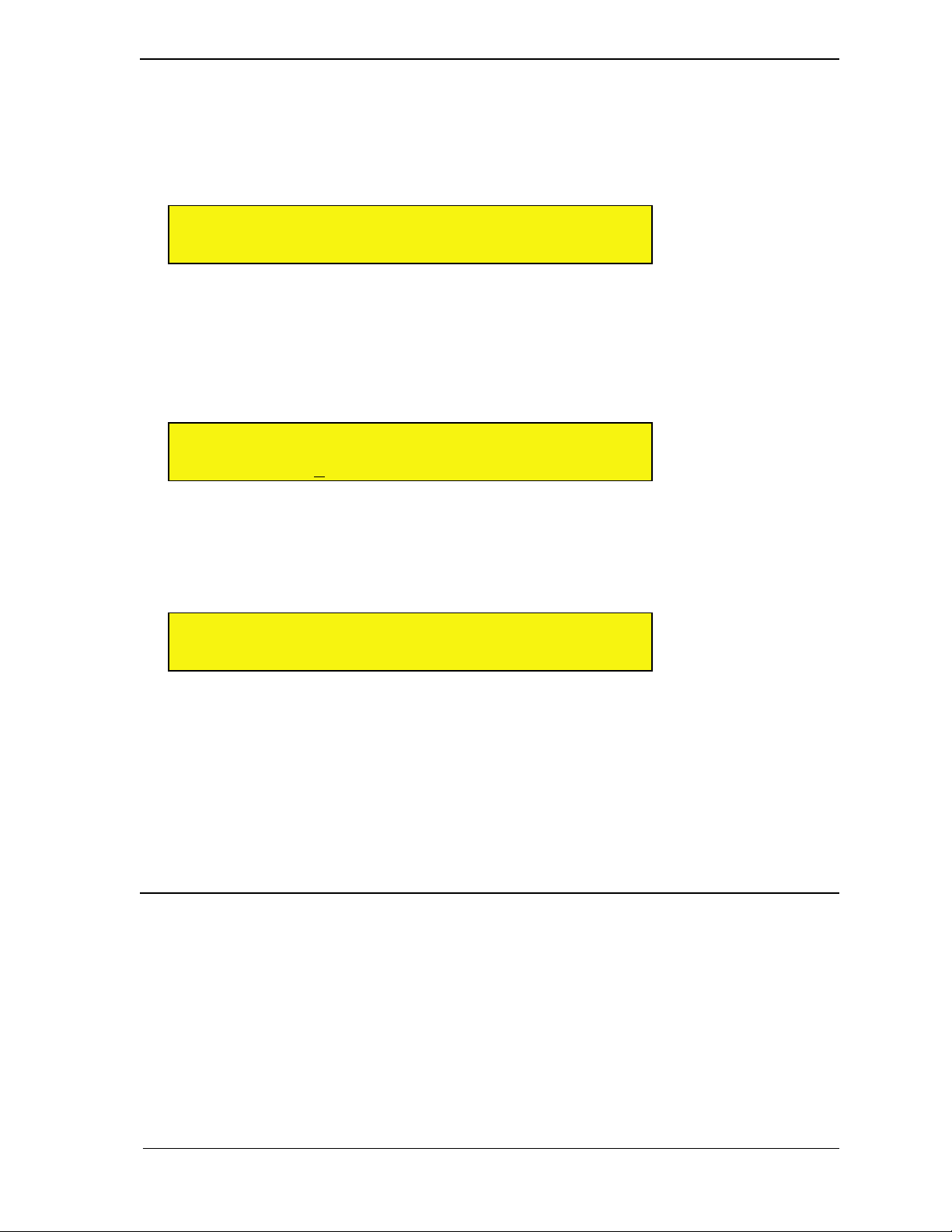
SETUP: TCP/IP Address
Rotate the top display knob to select the TCP/IP Address parameter. If Receptor is setup to use
Auto (DHCP) addressing (as described in the previous section), then the TCP/IP Address parameter is read-
only. If Receptor is setup to use Manual addressing, then you may change Receptor’s IP Address using this
parameter. Receptor uses this IP address to identify itself to another computer, which is how you will upload
new software and plugins.
S U T C P / I P A d d r e s s < >
III III 1 9 2 . 1 6 8 . 0 0 1 . 1 0 5
As mentioned, if the TCP/IP Setup parameter is set to Auto or Crossover, then this parameter is read-only. If
the TCP/IP Setup parameter is set to Manual, then you may edit the TCP/IP address as follows:
1 The IP Address is displayed in 4-blocks of 3-digit numbers. The cursor is under the left-most block and the
text is blinking. Rotate the bottom display knob to select the desired value (from 000-255), then press the
bottom display knob.
The cursor moves to the next block of numbers, which are flashing.
S U T C P / I P A d d r e s s < >
III III 1 9 2 . 1 6 8 . 0 0 1 . 1 0 5
2 Select the desired value for this block (from 000-255), then press the bottom display knob.
3 Continue until you’ve entered the desired IP address in all four blocks.
4 Press the bottom display knob after entering the fourth number block.
You’ll then be asked to enter the desired TCP/IP Netmask.
S U T C P / I P N e t m a s k < >
III III 2 5 5 . 2 5 5 . 2 5 5 . 0 0 0
5 Enter the netmask using the same technique used for entering the IP address, then press the bottom
display knob when finished.
If you don’t want to change the netmask, just press the bottom display knob to step through the fields without modifying
any of them.
You’ll then be asked to confirm your selection (Yes or No).
6 Rotate the bottom display knob to select Yes, then press the knob to apply your selection.
Receptor will update your TCP/IP settings — a process that will take a few seconds.
NOTE: The TCP/IP Netmask parameter is global and is not saved with a Multi Patch.
SETUP: TCP/IP Netmask
Rotate the top display knob to select the TCP/IP Netmask parameter. If Receptor is set up to use either
Auto (DHCP) or Crossover addressing (as described in the previous section), then the TCP/IP Netmask
parameter is read-only.
If Receptor is set up to use Manual addressing, then you may change Receptor’s Netmask as follows:
1 The Netmask is displayed in 4-blocks of 3-digit numbers. The cursor is under the left-most block and the
text is blinking. Rotate the bottom display knob to select the desired value (from 000-255), then press the
bottom display knob.
The cursor moves to the next block of numbers, which are flashing.
5: View Buttons in Depth 66 Receptor Manual
Page 67
S U T C P / I P N e t m a s k < >
III III 2 5 5 . 2 5 5 . 2 5 5 . 0 0 0
2 Select the desired value for this block (from 000-255), then press the bottom display knob.
3 Continue until you’ve entered the desired Netmask in all four blocks.
4 Press the bottom display knob after entering the fourth number block.
You’ll then be asked to confirm your selection (Yes or No).
5 Rotate the bottom display knob to select Yes, then press the knob to apply your selection.
Receptor will update your network settings — a process that will take a few seconds.
NOTE: The IP Address is a global parameter and is not saved with a Multi Patch.
SETUP: Windows Networking
Rotate the top display knob to select the Windows Networking parameter. Use this parameter to tell Receptor
whether or not to appear on a Windows Network. “Windows Networking” is the system whereby networked
Windows machines appear in each others’ ‘My Network Places’ (or ‘Network Neighborhood’ on older versions
of Windows).
S U W i n d o w s N e t w o r k i n g < >
III III O n
To turn Windows networking off:
1 Rotate the bottom display knob counter-clockwise to choose Off, then press it to apply your selection.
Receptor will update your network settings — a process that will take a few seconds. Receptor will no longer
appear on any Windows networks.
To turn Windows networking on:
1 Rotate the bottom display knob clockwise to choose On, then press it to apply your selection.
SETUP: Windows Workgroup
Rotate the top display knob to select the Windows Workgroup parameter. Use this parameter to view the name
of Receptor’s current Windows Workgroup, or to change the name of that workgroup. Windows Networking
uses ‘workgroups’ to gather up networked Windows machines into groups. Receptor, by default, joins the
‘Muse’ workgroup.
To change the name of Receptor’s Windows Workgroup:
1 Press the bottom display knob to rename the workgroup.
The top line changes to say “Rename,” and the bottom line displays the current workgroup name with a cursor under
the first character.
S U R e n a m e ( C u r s o r < > ) < >
III III M y - W o r k g r o u p
2 Rotate the top display knob to move the cursor. Rotate the bottom display knob to change the underlined
character.
To delete a character, press the top display knob and the underlined character will be deleted.
5: View Buttons in Depth 67 Receptor Manual
Page 68
3 Rotate the top and bottom display knobs to rename your workgroup, then press the bottom display knob to
apply the name change.
Receptor will update your network settings — a process that will take a few seconds. It will then appear on a Windows
network under the desired workgroup name.
NOTE 1: Network conventions allow the workgroup name to contain only alphanumeric characters, plus the
following special characters: ! , ‘ , - , # , $ , % , & , ( , )
NOTE 2: Spaces are not allowed in the workgroup name.
The Windows Workgroup setting is a global parameter and is not saved with a Multi patch
SETUP: Appletalk
Rotate the top display knob to select the Appletalk parameter. Use this parameter to tell Receptor whether or
not to appear on an Appletalk network.
S U A p p l e t a l k < >
III III O f f
Rotate the bottom display knob counter-clockwise to choose Off, and clockwise to choose On. Your choice
is flashing, indicating you must press the bottom display knob to apply your selection. If you select Off, then
Appletalk is turned off and you will not be able to see Receptor on an Appletalk network. If you select On, then
Receptor will appear on an Appletalk network.
The Appletalk setting is a global parameter and is not saved with a Multi Patch.
SETUP: Name
Rotate the top display knob to select the Name parameter. Rotate the bottom display knob to name this Receptor.
The name you enter here appears whenever this Receptor is found on a network.
IMPORTANT: If you’re using more than one Receptor, it’s important that each Receptor have a unique name
— otherwise the multiple units will not appear properly on a network. By default, Receptor ships with a rather
lengthy default name that makes it unlikely for multiple units to have identical names. If you change this default
name, make sure it doesn’t match the name used by another Receptor on your network.
To rename a Receptor:
1 Rotate the top display knob to select the Name parameter.
The second line of the display shows the current name of this Receptor.
S U N a m e < >
III III R e c e p t o r - 1 2 3 4 5 6
2 Press the bottom display knob to begin renaming Receptor.
The top line changes to say “Rename,” and the bottom line displays the current Receptor name with a cursor under the
first character.
3 Rotate the top display knob to move the cursor. Rotate the bottom display knob to change the underlined
character.
To delete a character, press the top display knob and the underlined character will be deleted.
S U R e n a m e ( C u r s o r < > ) < >
III III R e c e p t o r - 1 2 3 4 5 6
5: View Buttons in Depth 68 Receptor Manual
Page 69
4 Rotate the top and bottom display knobs to rename your Receptor, then press the bottom display knob to
apply the name change.
The display will say Are you sure? and blink.
S U A r e y o u s u r e ? < >
III III N o
5 Rotate the bottom display knob counter-clockwise to select No, or clockwise to select Yes. Make sure Yes
is shown and press the bottom display knob to apply.
Receptor’s Name is a global parameter and is not saved with a Multi Patch.
NOTE 1: Network conventions allow Receptor’s name to contain only alphanumeric characters, plus the
following special characters:
! , ‘ , - , # , $ , % , & , ( , )
Spaces are not allowed in Receptor’s name.
SETUP: System Version
Rotate the top display knob to select the System Version option. This displays Receptor’s current software
revision. The System Version is read-only -- you cannot edit it.
S U S y s t e m V e r s i o n < >
III III 1 . 0 . 0
SETUP: Hardware Version
Rotate the top display knob to select the Hardware Version option. This displays Receptor’s current
hardware revision number. The Hardware Version is read-only -- you cannot edit it.
S U H a r d w a r e V e r s i o n < >
III III 1 . 0 ( R e v B )
SETUP: Memory Free
Rotate the top display knob to select the Memory Free option. This displays information about Receptor’s
internal RAM. Specifically, it shows (in MB) the total amount of RAM installed in your Receptor and what
percentage of that RAM is currently free (unused). The Memory Usage page is read-only -- you cannot edit it.
S U M e m o r y F r e e < >
III III 8 7 % ( 5 1 2 M t o t a l )
5: View Buttons in Depth 69 Receptor Manual
Page 70
SETUP: Disk Free
Rotate the top display knob to select the Disk Free option. This displays information about Receptor’s
internal hard disk. Specifically, the second number (in parenthesis) shows the total amount of user-accessible
Hard Disk space. The first number shows how much of that hard disk space (in GB) is currently free (unused).
S U D i s k F r e e < >
III III 2 5 . 2 1 G ( 3 1 G t o t a l )
NOTE: You may wonder why the total amount of disk space does not equal the size of Receptor’s internal hard
drive. The reason is that this field displays the total amount of user accessible disk space. Some amount of
Receptor’s disk contains the operating system and the Receptor application, itself -- these applications cannot
be removed by the user and, as such, are not reported as part of the total disk space. The total disk space
display is, therefore, the total amount of disk space available for all plugins, patches, and samples.
SETUP: Enable Zload
Rotate the top display knob to select the Enable Zload option. Zload™, when enabled, can dramatically
improve the speed at which plugins instantiate. When plugins instantiate faster, Receptor is more responsive to
patch change requests. Multi patches, in particular, will load dramatically faster.
Zload works as follows: When you first instantiate a plugin, it takes the normal amount of time to load
(equivalent to the amount of time it takes to instantiate on a Mac or PC). Then, when you remove that plugin
from Receptor’s mixer, it’s set aside in RAM, rather than fully uninstantiated. The next time you try to
instantiate that plugin (either directly or by recalling a patch that uses that plugin), Receptor will re-use the
instance previously set aside in RAM, which is nearly instantaneous.
S U E n a b l e Z l o a d < >
III III D i s a b l e d
So why is Zload disabled by default? Because, regrettably, nothing in life is free. Since plugins, once
instantiated, are set aside in RAM, Zload demands a greater share of your Receptor’s RAM. In general, this
won’t be problematic, but there are a couple of things to consider when you’re deciding whether or not to use
Zload:
• Zloaded plugins will never max out your RAM. When Receptor has only 40% of its available RAM
remaining, then the oldest Zloaded plugins will be dropped, allowing you to regain the RAM that they
previously occupied. Obviously, the more RAM you add to Receptor, the more plugins that Receptor will
be able to set aside in RAM and the “snappier” the box will be.
• One possible downside to enabling Zload concerns customers who use large sample libraries. Because the
set-aside cache of Zloaded plugins may consume up to 60% of your unit’s available RAM, this memory
may not be available for loading samples. For example, if you have a sample that currently consumes 70%
of your Receptor’s memory, you’ll be able to load that sample as long as your Zloaded plugins haven’t
consumed more than 30% of your Receptor’s RAM. But, if your cache of Zloaded plugins exceeds 30%
of the available RAM, then the sample will not load. Again, the best remedy is to purchase and install
additional RAM into Receptor.
Obviously, to see the effects of Zload, a plugin must be instantiated at least once. But, once instantiated, that
plugin remains in RAM and any future instantiations will occur very quickly. If you tend to use a lot of the same
plugins in all your patches, then Zload will dramatically speed up plugin instantiation and patch loading.
When you turn Receptor off, all Zloaded plugins are cleared from RAM. This means, when you turn Receptor
back on, first instantiations of plugins will again occur at normal speed, but subsequent instantiations will be
very fast.
5: View Buttons in Depth 70 Receptor Manual
Page 71
Here are a couple more details you may wish to know about Zload:
• Some plugins keep audio in a buffer that does not get flushed when it’s set-aside by Zload. When this
happens, that plugin may make sound when re-loaded (since it will then empty its audio buffer). This
is a fairly rare occurrence and is pretty harmless in studio operations. But, if you’re using Receptor
live or sequencing with Single or Multi patch changes, you may want to check for this and, if it proves
problematic, disable Zload.
• Zload is currently disabled for all “Unsupported Plugins” whether you choose to enable Zload or not.
Future versions of Receptor will allow direct plugin-by-plugin control of Zload, so you can choose exactly
which plugins you want Zloaded and which you don’t.
Zload is a great asset that will greatly improve instantiation and patch loading speeds. Give it a try.
SETUP: Install/Upgrade
Rotate the top display knob to select the Install/Upgrade option. Use this option to install any software
updates, plugins, patches or other files currently contained in Receptor’s “Drop Installers Here” directory. For
more information about installation various file types, see “Drop Installers Here” on page 166.
S U I n s t a l l / U p g r a d e < >
III III 4 f i l e s
If there are currently files in Receptor’s “Drop Installers Here” folder, then the bottom line will read <n> files,
where <n> is the number of files currently in that directory. You must push the bottom display knob to install
files. If there are no files to install, the line will read None available.
To install files:
1 Press the bottom display knob to apply the installation process.
The screen will ask if you are sure you want to install.
S U A r e y o u s u r e ? < >
III III N o
2 Rotate the bottom display knob counter-clockwise to select No, or clockwise to select Yes. Make sure Yes
is shown and press the bottom display knob to apply.
The LCD reads “Installing...” as Receptor installs any package or patch files currently in its “Drop Installers Here”
folder. When installation is complete, the display will indicate how many files were successfully installed and how many
failed.
NOTE: Some installations (such as most system updates) will make Receptor automatically restart. If Receptor
needs to restart after installing an update, it will not display the number of successfully installed files.
SETUP: Uninstall Plugins
Rotate the top display knob to select the Uninstall Plugins option. Use this option to uninstall any plugin
currently installed within Receptor.
S U U n i n s t a l l P l u g i n s <
III III S u p e r S e x y S y n t h
To uninstall a plugin:
1 Rotate the bottom display knob to select the plugin you wish to uninstall.
The list will contain the name of every Receptor plugin in alphanumerical order. The plugin name is flashing, indicating
you must press the bottom display knob to apply it.
5: View Buttons in Depth 71 Receptor Manual
Page 72

2 Press the bottom display knob.
The screen will ask if you are sure you want to uninstall the selected plugin.
S U A r e y o u s u r e ? <
III III Y e s
3 Rotate the bottom display knob counter-clockwise to select No, or clockwise to select Yes. Make sure Yes
is shown and press the bottom display knob to apply.
Receptor uninstalls that plugin and all patch banks associated with that plugin.
5: View Buttons in Depth 72 Receptor Manual
Page 73
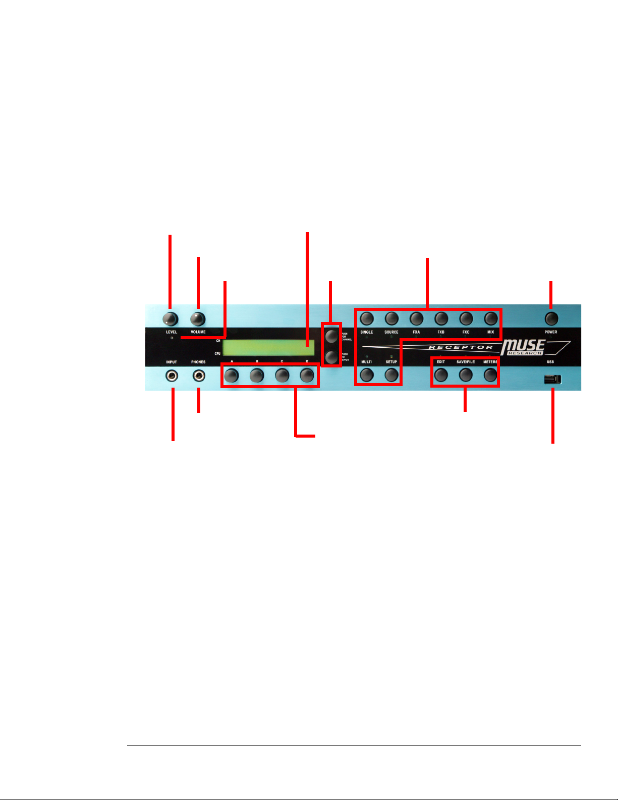
6 Editing, Saving, and Metering
This chapter discusses how to:
• Edit patches
• Save, copy, delete, and rename patches
• Meter the signal level at various points in the mixer
These functions are all performed using the three Modifier buttons on Receptor’s front panel.
Input Level
Guitar/Instrument Input USB Port
Modifier Basics
Basically, a Modifier button acts upon the patch or signal represented by the correspondingly lit View button.
• If the EDIT button is on, then you can select what you edit by pressing the corresponding View button and
selecting the desired channel. For example, if you wanted to edit the plugin assigned to FX B on Channel 2,
you would press EDIT, then FXB, then push/turn the top display knob to select Channel 2.
• If the SAVE/FILE button is on, then you can select what you want to save by pressing the corresponding
View button and selecting the desired channel. For example, if you wanted to save the patch assigned to
the SOURCE plugin on Channel 1, you would press SAVE, then SOURCE, then push/turn the top display
knob to select Channel 1.
• If the METERS button is on, then you can select what you want to monitor by pressing the corresponding
View button and selecting the desired channel. For example, if you wanted to see what the signal level is
at the output of Channel 3, you would press METERS, then MIX, then push/turn the top display knob to
select Channel 3.
Master Volume
Input Level LED
Headphone Jack
LCD
Display Knobs
Soft Knobs
View Buttons
Power Button
Modifier Buttons
6: Editing, Saving, and Metering 73 Receptor Manual
Page 74

EDIT Button
One of the many advantages of VST plugins is that each plugin can have a unique graphical interface to make
editing easy. Receptor supports graphical plugin editing via its built-in keyboard, mouse, and monitor inputs
(discussed in the “Graphic Editor” section on page 85) or by remote computer control (discussed in “Remote
Control of Receptor” on page 174). However, there may be times when you may want to “tweak” a patch via
Receptor’s front panel. This is what Edit Mode is for.
Each plugin that ships with Receptor has a factory-determined collection of parameters assigned to appear on
the front panel when you enter Edit Mode. In addition, Receptor supports direct editing of up to 4 parameters
using the four dedicated soft knobs on the front panel. Think of this almost like having a small built-in MIDI
control surface!
Using Receptor’s graphical UI, you can change those factory defaults: adding, removing, or rearranging the
parameters that appear on the front panel (see “Learn Mode” on page 113 to learn how).
Like all of Receptor’s Modifier buttons, the EDIT button works in conjunction with one of the View buttons.
For example, if you want to edit a synthesizer plugin assigned to the SOURCE slot on Channel 5, you would:
1 Press SOURCE.
This tells Receptor you want to edit a VSTi plugin.
2 Press the top display knob to enter Channel Select Mode, then rotate it to select Channel 05. Press it again
to exit Channel Select Mode.
This tells Receptor that you want to edit the VSTi assigned to Channel 5.
3 Press EDIT.
This puts Receptor into Edit Mode.
You can exit Edit Mode at any time by simply pressing the EDIT button again to turn it off.
The parameters available in Edit Mode depend completely on the type of plugin or patch you’re editing.
However, all patches are edited using an identical methodology.
EDIT: <Parameter>
Receptor can define, for each plugin, which parameters should be displayed on the front panel and in what
order they should be displayed (as discussed in “Learn Mode” on page 113). These parameters appear whenever
Receptor is in Edit mode and is set to view an instantiated Source or FX.
0 1 F i l t e r F r e q u e n c y >
III III 2 7
Rotate the top display knob to scroll through the list of parameters. Rotate the bottom knob to change the value
of the indicated parameter.
NOTE: Parameter editing exists only for VST effects and instruments. If you press EDIT when the SINGLE,
MULTI, or MIX buttons are lit, you’ll see that Edit Mode is not available.
EDIT: Using the Soft Knobs
By default, Receptor assigns the first four parameters to the four soft knobs on the front panel. For example, an
“analog” synth plugin might have its first four parameters assigned to:
• Frequency
• Resonance
• Attack
• Release
6: Editing, Saving, and Metering 74 Receptor Manual
Page 75

In this example, if you turned Soft Knob B, the display would change to display the “Resonance” parameter,
and you would see its value change as you rotated the knob. When you stop rotating a soft knob, the display
returns to normal within about a half-second.
If you want to see which parameter is assigned to a soft knob without actually turning it, simply push the soft
knob -- the display will show the associated parameter name and value for a period of about one second.
In effect, this gives you instant and simultaneous control of up to five parameters: the first four plus whichever
parameter you’ve scrolled to using the top display knob.
EDIT: “Panic” Feature
The EDIT button performs a special “panic” function when used with Setup Mode. Specifically, if you ever
experience a situation in which a note gets stuck “on,” simply press the SETUP button followed by the EDIT
button. This “panic” feature sends an all notes off MIDI message to all 16 of Receptor’s instrument channels,
silencing any note that might be stuck on.
SAVE/FILE Button
Press SAVE/FILE to enter Save/File Mode. Within Save/File Mode you can save, delete, copy, and rename any
bank or patch type supported by Receptor. This includes:
• Single patches - A single patch contains a single Instrument’s SOURCE assignment plus all its in line FX
plugin/patch assignments and their routing.
• Multi patches - A multi patch contains all Instrument channels, the two effects bus channels, and the master
channel settings -- essentially an entire Receptor configuration.
• Plugin patches - A plugin patch is the standard .fxp patch associated with a particular plugin. Each VST
instrument and effect has its own patch format and all are supported by Receptor.
Note: When the SETUP button is lit, press the SAVE/FILE button to see a screen showing you an overview of
Receptor’s 19 channels and their current status. For more information, see “SETUP: Channel Status” on page
59.
Even though Receptor supports so many types of patch formats, the method used to save, copy, delete or rename
them is the identical. For example, if you wanted to save the edits you made to an effect assigned to FX B of
Channel 3, you would:
1 Press FX B.
This tells Receptor that you want to perform your operations on FX B.
2 Press the top display knob to enter Channel Select Mode, then rotate it to select Channel 03. Press it again
to exit Channel Select Mode.
This tells Receptor that you want to perform your operations on the FX B assigned to Channel 3.
3 Press SAVE.
This puts Receptor into Save Mode.
NOTE: If you try to SAVE a patch for a slot that currently has no plugin assigned, the display will say “Save/
File Mode Unavailable.” You can cancel the Save operation at any time by simply hitting the SAVE button
again to turn off Save Mode.
The following sections discuss each of the options available in Save Mode.
6: Editing, Saving, and Metering 75 Receptor Manual
Page 76
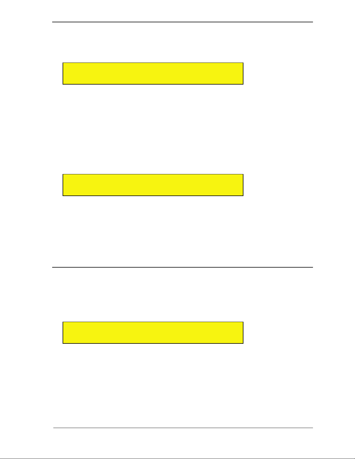
SAVE/FILE: Save Patch
Rotate the top display knob to select the Save Patch option. This operation will overwrite the patch stored on
disk with what’s in the edit buffer. If you want to save the patch to a different bank or rename the patch prior to
saving it, you must use the Save Patch As option, discussed in the next section.
0 1 S a v e S n g l P a t c h >
III III 0 5 2 : A m a n d a L y n n
The top line of the display appears in the following format...
Save <type> Patch
...where <type> is the type of patch selected with the view buttons (MULTI, SINGLE, SOURCE, FX A, FX B,
or FX C).
The bottom line displays the current patch name and number, which is flashing to indicate that you must press
the bottom display knob to apply your selection.
To save a patch over the existing location:
1 Simply press the bottom display knob.
Receptor asks you to confirm whether you want to overwrite this patch.
0 1 A r e y o u s u r e ? >
III III N o
2 Rotate the bottom display knob counter-clockwise to select No, or clockwise to select Yes. Make sure Yes
is shown and press the bottom display knob to apply.
Receptor overwrites the patch at the selected location.
NOTE: Receptor’s Factory patches are ROM patches, meaning you cannot overwrite or delete them. ROM
banks and patches have angle brackets around their names, like <this>. If you modify a ROM patch and try to
save it, the Save Patch option will not be available. Your first Save option will therefore be Save Patch As,
discussed next. For more information, see “ROM Banks and RAM Banks” on page 127.
SAVE/FILE: Save Patch As
Rotate the top display knob to select the Save Patch As option. Use this option to save the current patch edit
to any bank and patch location, using any patch name you choose. Selecting this option will present you with a
number of pages to step through in which you can select which Bank to save the patch in (including creation of
a new bank), which patch number to save it to, and what to name it. Don’t worry, Receptor guides your process
every step of the way.
0 1 S a v e S n g l P a t c h A s < >
III III B a n k : M e l l o w S o u n d s
The top line of the display appears in the following format...
Save <type> Patch As
... where <type> is the type of patch selected with the view buttons (MULTI, SINGLE, SOURCE, FX A, FX B,
or FX C).
The bottom line initially displays the current bank name, which is flashing.
If you wish to save the patch to the current bank:
1 Simply press the bottom display knob and proceed to step 6.
6: Editing, Saving, and Metering 76 Receptor Manual
Page 77
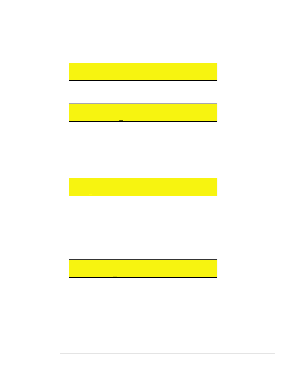
If you wish to store the patch within a different bank:
2 Rotate the bottom display knob to select a different bank.
The bank name is flashing, indicating you must press the bottom display knob to apply the change.
3 Press the bottom display knob to apply your selection and proceed to Step 7.
4 If, when selecting a bank, you decide you want to create a new bank in which to store the patch, rotate the
bottom display knob to the very end, at which point the display will read Bank:(NEW).
0 1 S a v e S n g l P a t c h A s < >
III III B a n k : ( N E W )
The display will now allow you to rename the bank. Receptor automatically creates a new bank with the name
BANK n, where “n” represents the order number of the bank.
0 1 R e n a m e ( C u r s o r < > ) < >
III III B a n k : B a n k 5
5 Rotate the top display knob to move the cursor. Rotate the bottom display knob to change the underlined
character.
To delete a character, press the top display knob and the underlined character will be deleted.
6 Rotate the top and bottom display knobs to rename your bank, then press the bottom display knob to
apply the name change.
7 The bottom line of the display is now used for selecting which of that bank’s 128 patch locations should
store your patch.
0 1 S a v e S n g l P a t c h A s < >
III III 0 5 2 : A m a n d a L y n n
8 If you wish to overwrite this patch, simply press the bottom display knob and proceed to step 10.
9 If you wish to save the patch to a different patch number, rotate the bottom display knob to select the
desired patch number.
The patch number is underlined and flashing, indicating you must press the bottom display knob to apply your
selection. If a patch location is currently empty, the display reads (empty).
10 Press the bottom display knob to apply your selection.
11 The display will now allow you to rename the patch, if you desire. If you don’t wish to rename the patch,
simply press the bottom display knob and continue to Step 12.
0 1 R e n a m e ( C u r s o r < > ) < >
III III 0 5 2 : A m a n d a L y n n
Rotate the top display knob to move the cursor. Rotate the bottom display knob to change the character over which the
cursor appears. The entire patch name flashes, indicating you must press the bottom display knob to apply the name
change.
NOTE: You can delete the underlined character by pressing the top display knob.
12 Rotate the top and bottom display knobs to rename your bank, then press the bottom display knob to
apply the name change.
6: Editing, Saving, and Metering 77 Receptor Manual
Page 78
13 Receptor asks you to confirm the save operation.
0 1 A r e y o u s u r e ? < >
III III N o
14 Rotate the bottom display knob counter-clockwise to select No, or clockwise to select Yes. Make sure Yes
is shown and press the bottom display knob to apply.
Receptor overwrites the patch at the selected location.
SAVE/FILE: Copy Patch
Rotate the top display knob to select the Copy Patch option. Use this option to copy any patch (of a particular
type) to a new location.
0 1 C o p y P a t c h F r o m < >
III III B a n k : M e l l o w S o u n d s
Patch copying is a multi-page option. You must first tell Receptor which Bank to look in, then which Patch to
copy before confirming your choice.
1 Rotate the bottom display knob to select the bank containing the patch you wish to copy.
The bank name is flashing, indicating you must press the bottom display knob to apply your selection.
2 Press the bottom display knob to apply your selection.
The bottom line of the display is now used for selecting which of that bank’s 128 patches you wish to copy from. The
patch number is underlined and flashing indicating you must press the bottom display knob to apply your selection.
0 1 C o p y P a t c h F r o m < >
III III 0 5 2 : A m a n d a L y n n
3 Rotate the bottom display knob to select the patch you wish to copy then press it to apply your selection.
The top line of the display now reads Copy Patch To and the bottom line displays the current bank name.
0 1 C o p y P a t c h T o < >
III III B a n k : M e l l o w S o u n d s
4 Rotate the bottom display knob to select the bank you wish to copy the patch to.
The bank name is flashing, indicating you must press the bottom display knob to apply your selection.
5 Press the bottom display knob to apply your selection.
The bottom line of the display is now used for selecting which of that bank’s 128 patches you wish to copy to. The patch
number is underlined and flashing, indicating you must press the bottom display knob to apply your selection.
0 1 C o p y P a t c h T o < >
III III 0 7 5 : ( e m p t y )
6 Rotate the bottom display knob to select the patch number you wish to copy to.
If a patch location is currently empty, the display reads (empty).
7 Press the bottom display knob to apply your selection.
The display will say Are you sure? and blink.
6: Editing, Saving, and Metering 78 Receptor Manual
Page 79
0 1 A r e y o u s u r e ? < >
III III N o
8 Rotate the bottom display knob counter-clockwise to select No, or clockwise to select Yes. Make sure Yes
is shown and press the bottom display knob to apply.
Receptor copies the patch to this location, naming it <original patch name>-C. For example, if you copied a
patch named, “Claire Annette” to another location, the copied patch would be named Claire Annette-C.
You can always rename a bank or patch using the Rename option discussed in “SAVE/FILE: Rename Bank” on page
80.
SAVE/FILE: Delete Bank
To delete an entire bank of patches:
1 Rotate the top display knob to select Delete Bank.
2 Rotate the bottom display knob to select the bank you wish to delete.
The bank name is flashing, indicating you must press the bottom display knob to apply your selection.
0 1 D e l e t e B a n k < >
III III B a n k : E x p e r i m e n t s
3 Press the bottom display knob to apply your selection.
The display will ask if you’re sure.
0 1 A r e y o u s u r e ? < >
III III N o
4 Rotate the bottom display knob counter-clockwise to select No, or clockwise to select Yes. Make sure Yes
is shown and press the bottom display knob to apply.
IMPORTANT: Receptor will delete the entire bank and all patches contained within it, so be careful.
SAVE/FILE: Delete Patch
To delete a patch:
1 Rotate the top display knob to select Delete Patch.
2 Rotate the bottom display knob to select the bank that contains the patch you wish to delete.
The bank name is flashing, indicating you must press the bottom display knob to apply your selection.
0 1 D e l e t e P a t c h < >
III III B a n k : E x p e r i m e n t s
3 Press the bottom display knob to apply.
The bottom line of the display is now used for selecting which of that bank’s 128 patches you wish to delete.
4 Rotate the bottom display knob to select the patch you wish to delete.
The patch number is underlined and flashing, indicating you must press the bottom display knob to apply your
selection.
6: Editing, Saving, and Metering 79 Receptor Manual
Page 80
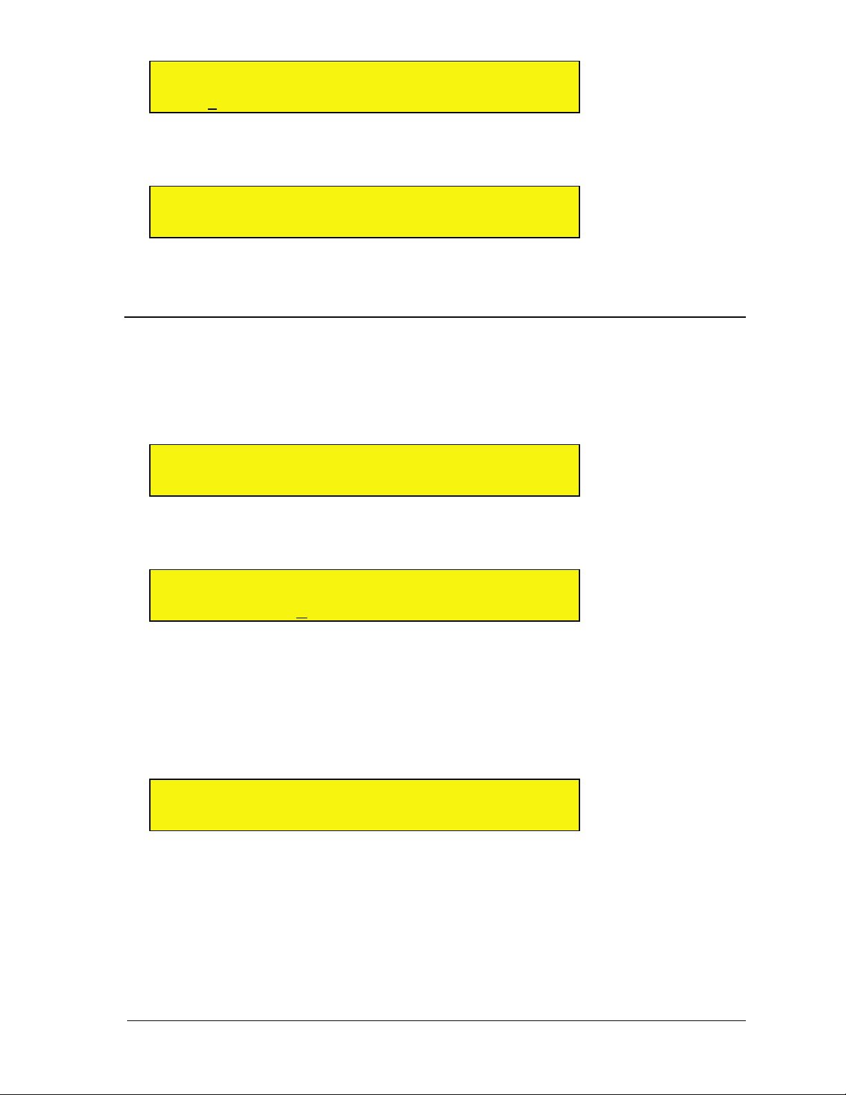
0 1 D e l e t e P a t c h < >
III III 0 5 2 : S q u i r r e l ‘ s N u t
5 Press the bottom display knob to apply your selection.
The display will ask if you’re sure.
0 1 A r e y o u s u r e ? < >
III III N o
6 Rotate the bottom display knob counter-clockwise to select No, or clockwise to select Yes. Make sure Yes
is shown and press the bottom display knob to apply.
SAVE/FILE: Rename Bank
To rename any bank in Receptor:
1 Rotate the top display knob to select the Rename Bank option.
2 Rotate the bottom display knob to select the bank you wish to rename.
The bank name is flashing, indicating you must press the bottom display knob to apply your selection.
0 1 R e n a m e B a n k < >
III III B a n k : B A N K 5
3 Press the bottom display knob to apply your selection.
The display will now allow you to rename the bank.
0 1 R e n a m e ( C u r s o r < > ) < >
III III B a n k : B A N K 5
Rotate the top display knob to move the cursor. Rotate the bottom display knob to change the character over which the
cursor appears. The entire bank name flashes, indicating you must press the bottom display knob to apply the name
change.
NOTE: You can delete the underlined character by pressing the top display knob.
4 Rotate the top and bottom display knobs to rename your bank, then press the bottom display knob to
apply the name change.
The display will as if you’re sure.
0 1 A r e y o u s u r e ? < >
III III N o
5 Rotate the bottom display knob counter-clockwise to select No, or clockwise to select Yes. Make sure Yes
is shown and press the bottom display knob to apply.
6: Editing, Saving, and Metering 80 Receptor Manual
Page 81
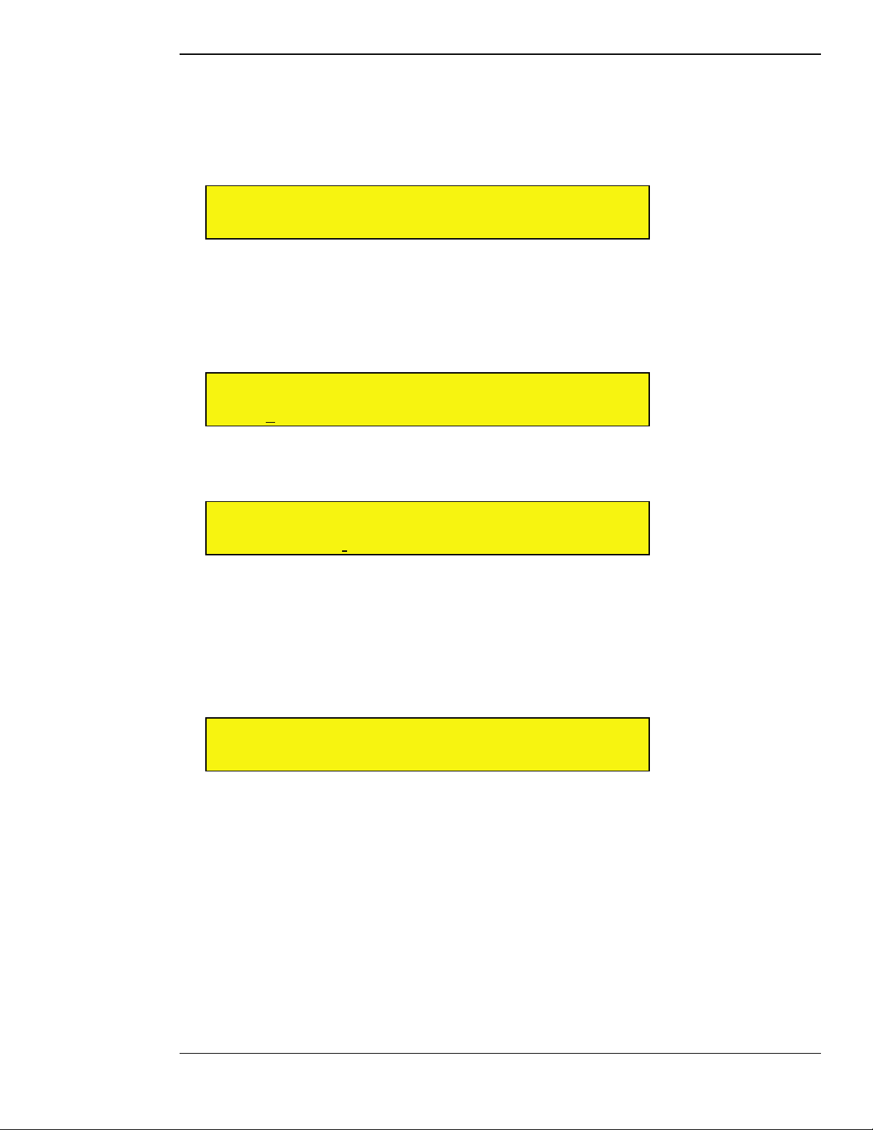
SAVE/FILE: Rename Patch
To rename a patch:
1 Rotate the top display knob to select the Rename Patch option.
2 Rotate the bottom display knob to select the bank that contains the patch you wish to rename.
The bank name is flashing, indicating you must press the bottom display knob to apply your selection.
0 1 R e n a m e P a t c h <
III III B a n k : M e l l o w S o u n d s
3 Press the bottom display knob to apply.
The bottom line of the display is now used for selecting which of that bank’s 128 patches you wish to rename.
4 Rotate the bottom display knob to select the patch you wish to rename.
The patch number is underlined and flashing, indicating you must press the bottom display knob to apply your
selection.
0 1 R e n a m e P a t c h <
III III 0 2 6 : f u n K E Y
5 Press the bottom display knob to apply your selection.
The display will now allow you to rename the patch.
0 1 R e n a m e ( C u r s o r < > ) <
III III 0 2 6 : f u n K E Y
Rotate the top display knob to move the cursor. Rotate the bottom display knob to change the character over which the
cursor appears. The entire patch name flashes, indicating you must press the bottom display knob to apply the name
change.
NOTE: You can delete the underlined character by pressing the top display knob.
6 Rotate the top and bottom display knobs to rename your bank, then press the bottom display knob to
apply the name change.
The display will ask if you’re sure.
0 1 A r e y o u s u r e ? <
III III N o
7 Rotate the bottom display knob counter-clockwise to select No, or clockwise to select Yes. Make sure Yes
is shown and press the bottom display knob to apply.
6: Editing, Saving, and Metering 81 Receptor Manual
Page 82
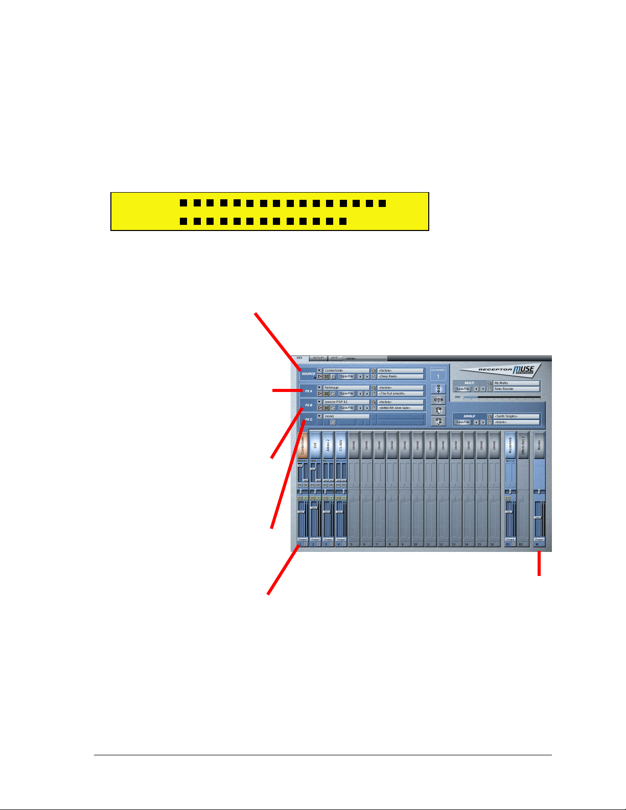
Meters Mode
Receptor is a completely modular and flexible synth and effects device. Because of this, there may be times
when you’ve inserted a particular plugin that dramatically affects either the signal level for a particular channel
or the overall CPU load on Receptor.
Meters Mode performs three functions:
• It lets you to view the signal level at any point within Receptor’s multi-channel signal chain.
• It lets you to view the CPU load for any individual plugin.
• When used in conjunction with the SETUP button, it lets you monitor MIDI input activity (see “SETUP:
MIDI Monitor” on page 60).
0 1 L : !
III III R :
In general, if you press one of the View buttons followed by the METERS button, you’ll monitor both the CPU
usage of that particular plugin, plus the signal level at the output of that plugin.
If you’re familiar with Receptor’s Graphical view, the following illustration shows you all the various places
that you can “tap” the signal and meter it.
Press SOURCE then
METERS to view the CPU
usage of this plugin, plus the
signal level at the output of
this plugin.
Press FX A then METERS to
view the CPU usage of this
plugin, plus the signal level at
the output of this plugin.
Press FX B then METERS to
view the CPU usage of this
plugin, plus the signal level at
the output of this plugin.
Press FX C then METERS to
view the CPU usage of this
plugin, plus the signal level at
the output of this plugin.
Press MIX (or SINGLE) then
METERS to view the CPU
usage of this channel, plus
the signal level at the output
of this channel.
Press MULTI then METERS
to view the CPU usage of
the entire Receptor, plus
the master signal level at
Receptor’s stereo output.
6: Editing, Saving, and Metering 82 Receptor Manual
Page 83

Metering Signal Levels
Like all of Receptor’s Modifier buttons, the METERS button works in conjunction with one of the view
buttons.
For example, if you want to monitor the signal level present at the output of Channel 3, you would:
1 Press the top display knob to enter Channel Select Mode, then rotate it to select Channel 03. Press it again
to exit Channel Select Mode.
This tells Receptor that it’s Channel 3’s Mix level you want to monitor.
2 Press MIX.
This tells Receptor you want to meter the signal at the output of the Mix channel.
3 Press METERS.
This puts Receptor into Meters Mode.
If a signal clips, it’s indicated by an exclamation point at the far right of the LCD. To clear the clipping indicators,
press the bottom display knob.
4 Exit Meters Mode at any time by simply pressing the METERS button again to turn it off.
As you can see, this is a fairly powerful feature, since it lets you meter the signal level at any part of the audio
chain. For example, if you wanted to meter the signal level coming out of the VSTi assigned to Ch 1 before it
reaches the effect stack, you would:
1 Select Channel 1.
2 Press SOURCE.
3 Press METERS.
NOTE: If Receptor is in SINGLE view when you press the METERS button, the display shows the output of the
current channel (just as if you were in MIX view). If Receptor is in MULTI view when you press the METERS
button, the display shows the output of Receptor’s Master channel (just as if you were in MIX View and had
selected the Master (“M”) channel.
Metering CPU Usage
Usually, the 2-character CPU gauge in the lower-left corner of the LCD displays the overall CPU load currently
used by Receptor. However, there may be times when you want to see exactly how much CPU a particular
plugin uses. This, too, is another use for Meters Mode.
Once you’ve put Receptor into Meters Mode, the CPU gauge indicates the CPU usage of a particular plugin or
channel (rather than the global CPU load on Receptor). For example, to see exactly how much CPU processing
is required to play a VSTi synthesizer instantiated on Ch 2, you would:
1 Select Channel 2.
2 Press SOURCE.
3 Press METERS.
The CPU gauge would show you how much CPU that particular VSTi (Source) was using on that particular channel.
METERS: “Load Blank Patch” Shortcut
The METERS button performs a special shotcut when you press it with Receptor in Setup Mode. Specifically, if
you press the SETUP button, then press the METERS button, Receptor will load a blank Multi patch, just as if
you chose this option from MULTI view (as discussed on page 43). This is simply a shortcut that allows you to
quickly load a blank Multi patch into Receptor, giving you a clean slate with which to begin building patches.
6: Editing, Saving, and Metering 83 Receptor Manual
Page 84

6: Editing, Saving, and Metering 84 Receptor Manual
Page 85

Graphic Editor
This section discusses Receptor’s built-in graphic editor, which is available
by either connecting a keyboard, monitor, and mouse directly to Receptor; or
remotely controlling it from a computer using Ethernet.
Graphic Editor 85 Receptor Manual
Page 86

Graphic Editor 86 Receptor Manual
Page 87
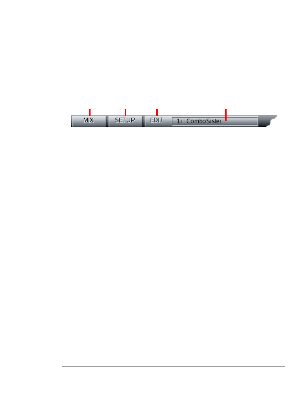
7 Graphic UI - Mix View
Receptor’s editing capabilities are enhanced by connecting a monitor, keyboard and mouse directly to the
unit, or by networking Receptor with a computer and controlling it from that computer. Both of these methods
employ the same graphical user interface, which is described in this and the following “Graphic UI” chapters.
Receptor is designed to run full-screen on a 1024x768 pixel monitor. Different views are accessed by clicking
the various tabs in the View Bar.
Mix Button Setup Button Edit Button Editor Select Button
--- View Bar Buttons ---
The main Receptor views are:
• Mix View – Click the Mix button to see Mix View, which is where you configure Receptor’s 16 instrument
channels, 2 effect bus channels, and its master channel. Mix View is discussed thoroughly in this chapter.
• Setup View – Click the Setup button to see Setup View, which is where you set global MIDI and
communication parameters, and various preferences. Setup View is discussed thoroughly in Chapter 9,
“Graphic UI - Setup View”.
• Edit View – Click the Edit button to see Edit View, which is where you edit any instantiated plugin on
Receptor. To select which plugin to edit, click the Edit Select button and select from the list of currently
instantiated plugins. Edit View is discussed thoroughly in Chapter 8, “Graphic UI - Edit View”.
7: Graphic UI - Mix View 87 Receptor Manual
Page 88
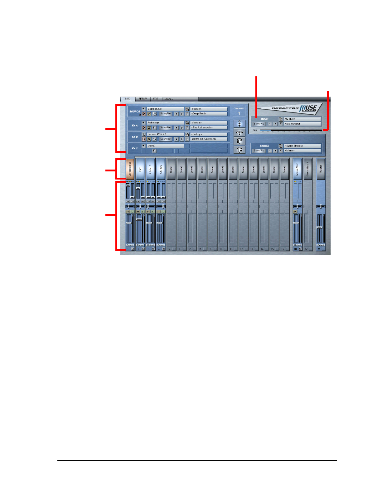
Overview of Mix View
Mix View is Receptor’s main and default view. It’s where you configure Receptor’s 16 instrument channels,
2 effect bus channels, and its master channel. As you can see in the following illustration, Mix View contains
five basic areas.
Channel
Details
Channel
Selectors
Multi Patch
CPU Gauge
Mixer
--- Mix View’s Five Basic Areas ---
Basic operation couldn’t be simpler. Across the bottom of the screen are all 19 Receptor channels. The top of
the screen is a detailed view of one of those channels.
To assign an audio input, VST instrument or effect to a particular channel, simply open that channel’s detail by
clicking the big Channel Selector button. Click the Source selector and select a plugin from the Plugin Select
panel that appears. Use the bank/patch selectors to select the desired patch.
Use the mixer at the bottom of the screen to adjust volume, pan, and effect sends.
Receptor’s graphical interface shows you only what is relevant. For example, if a channel has no plugins
assigned to it, then it is disabled in the mixer. Similarly, Channel Details show you only those parameters that
are currently accessible. For example, a plugin’s bank and patch selection parameters are not available until you
actually select a plugin.
The following sections discuss the various Mix View elements in detail.
7: Graphic UI - Mix View 88 Receptor Manual
Page 89
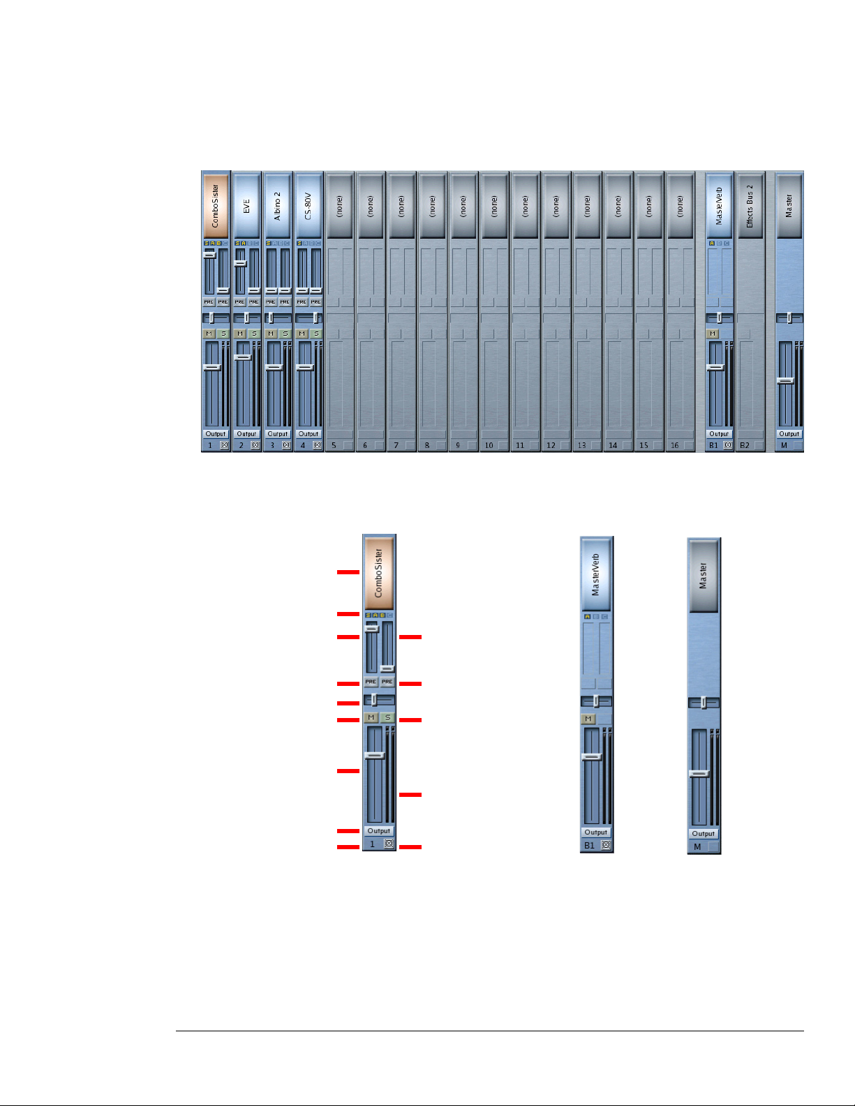
Mixer Anatomy
The bottom half of the Mix View windows shows... you guessed it... a MIXER! Receptor has 16 different
instrument channels, each of which derives its sound from either a built-in VSTi or from an external audio
input. In addition, Receptor has two dedicated effects busses and a master output channel, resulting in a mixer
with 19 total channels strips.
--- Mixer ---
The following illustration shows, in detail, the elements contained in each type of mixer channel.
Instrument Channel
Effects Bus
Master Channel
Channel Selector
Plugin Overview
Send 1 Level
Send 1
Pre/Post Fader
Send 2 Level
Send 2
Pre/Post Fader
Pan/Balance
Mute
Solo
Volume
Channel Level
Output
Assignment
Channel Number
--- Mixer Channel Strip Details ---
NOTE: These parameters are the same as those accessed from the MIX button on Receptor’s front panel. In
most instances, Receptor’s Graphical User Interface mirrors its front panel operations quite closely.
The following sections discuss, from top-to-bottom, each mixer channel parameter illustrated above.
Channel Bypass
7: Graphic UI - Mix View 89 Receptor Manual
Page 90
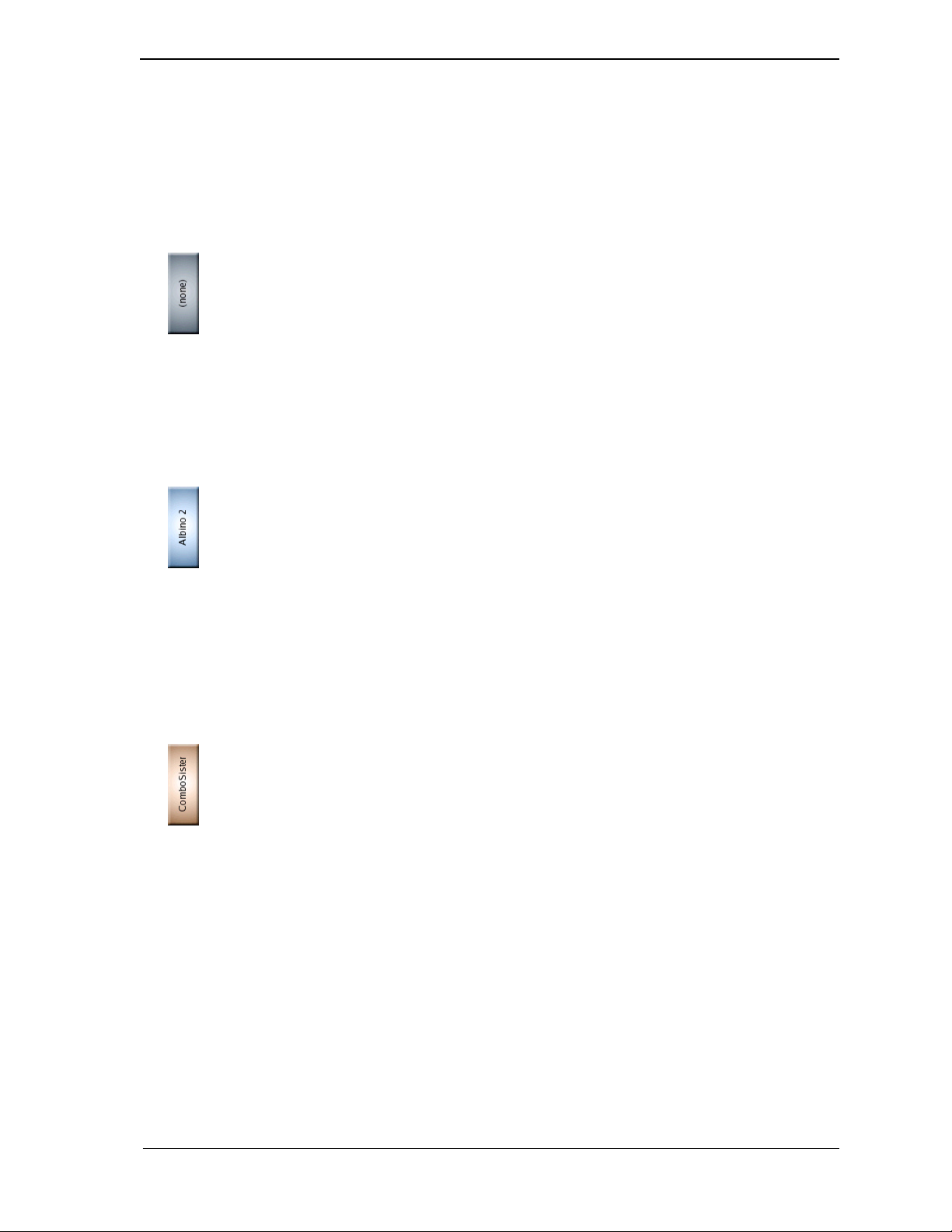
Channel Selector
The giant glowing button at the top of a mixer channel is the Channel Selector. By default, Channel Selectors
always display the name of the Source, with the exception of the two busses and master, which display the
name of the first instantiated effect. Click a Channel Selector to view all the information for that channel in the
upper Channel Details area. The Channel Details area (as discussed in “Channel Details Overview” on page 94)
is where you assign instruments, effects, and patches to each channel, so these buttons will get quite a virtual
workout.
Basically, the Channel Selector works as follows:
• When a Channel Selector is gray (as seen above), it means that a channel does not have any plugins
assigned to it and it displays “(none)” as the track name. Click a gray Channel Selector to display the
Channel Details area for that channel. Once the Channel Details are displayed, you may assign a sound
Source and various insert effects to a channel.
SHORTCUT: Shift-click a gray Channel Selector to open a Source Select panel for that channel. This saves
you a step since you don’t have to display the Channel Details before you select a Source.
• When a button is blue (as seen above), it means that one or more plugins are assigned to that channel
but that channel is not currently visible in the Channel Detail at the top of the screen. If you click a blue
Channel Selector, it will turn orange, and that channel’s parameters will appear in the Channel Detail area.
SHORTCUT: Shift-click a blue Channel Selector to open a Source Select panel for that channel. This lets
you instantiate a different Source without first opening the Channel Detail area. Ctl-click a blue Channel
Selector to uninstantiate all plugins on that channel, thus clearing it in one swift action.
• When a button is orange (as seen above), it means that one or more plugins are assigned to that channel and
that it’s the channel whose parameters are currently visible in the Channel Details at the top of the screen.
SHORTCUT: Shift-click an orange Channel Selector to open a Source Select panel for that channel. This
lets you instantiate a different Source without first opening the Channel Detail area. Ctl-click an orange
Channel Selector to uninstantiate all plugins on that channel, thus clearing it in one swift action.
7: Graphic UI - Mix View 90 Receptor Manual
Page 91
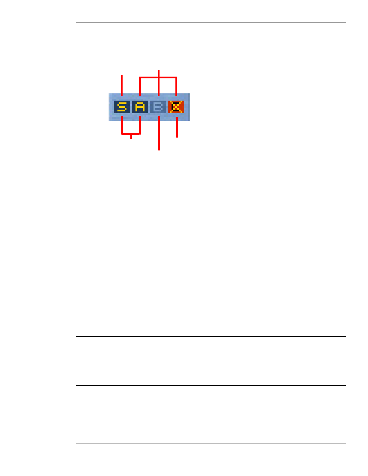
Plugin Overview
The Plugin Overview icons may be tiny, but they’re very useful. They provide a visual overview of all the
plugins in Receptor. With a quick glance, you can see which channels have instantiated plugins and which
channels have bypassed plugins.
Source Icon
Instantiated Plugins
FX A, B, C Icons
Bypassed Plugin
Uninstantiated Plugin
These icons can be quite useful when trying to track down a rogue plugin that might be hijacking Receptor’s
valuable CPU resources.
Send 1 Level
Use this fader to set how much signal to send to Receptor’s Effects Bus 1 (whose effect chain is configured in
the B1 channel).
NOTE: Send Levels are not present in the Effects Bus channels nor the Master channel.
Send 1 Pre/Post button
This button determines whether the signal is routed to Effects Bus 1 before (pre) or after (post) going through
the channel volume.
In the default post fader position (the button is dark), changing the strip’s volume level changes the amount of
effected signal proportionately.
In the pre fader position (the button is on and purple in color), the Send Level and Volume level act
independently. This is useful if, for example, you wish to hear only an effected signal with no dry signal, which
you would accomplish by turning on the Pre Fader button and setting the Volume level to zero.
NOTE: Since Send Levels are not present in the Effects Bus channels or the Master channel, neither are the
Pre/Post buttons.
Send 2 Level
Use this fader to set how much signal to send to Effects Bus 2 (whose effect chain is configured in the B2
channel).
NOTE: Send Levels are not present in the Effects Bus channels nor the Master channel.
Send 2 Pre/Post button
This button determines whether the signal is routed to Effects Bus 2 before (pre) or after (post) going through
the channel volume.
In the default post fader position (the button is dark), changing the strip’s volume level changes the amount of
effected signal proportionately.
7: Graphic UI - Mix View 91 Receptor Manual
Page 92
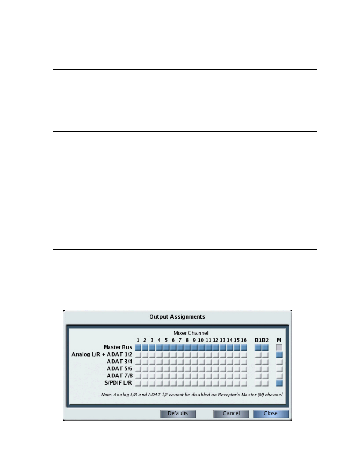
In the pre fader position (the button is on and purple in color) the Send Level and Volume level act
independently. This is useful if, for example, you wish to hear only an effected signal with no dry signal, which
you would accomplish by turning on the Pre Fader button and setting the Volume level to zero.
NOTE: Since Send Levels are not present in the Effects Bus channels or the Master channel, neither are the
Pre/Post buttons.
Pan/Balance
Slide the Pan/Balance fader left and right to position the Instrument in the stereo field. Control-click the fader to
reset it to the default center position.
All Receptor channels are stereo so, if an instantiated plugin is actually mono, Receptor will double the signal
such that the left and right channels are identical. In the case of mono plugins, this parameter works like a
traditional pan control. In the case of stereo plugins, it acts as a balance control.
Mute
Below the Pan fader is the Mute button (as indicated by the “M”). Click the Mute button to disable a channel’s
output. Muted channels are also indicated in the Meter Bridge. Plugins on a muted channel are still active and
using CPU resources. Use the Bypass button if you want to mute a plugin (or channel) and also free up CPU
resources.
NOTE: Mute and Solo buttons are not present in the Master channel.
Solo
To the right of the Mute button is the Solo button (as indicated by the “S”). Click the Solo button to hear only
this (and any other soloed) channels. Soloing a channel automatically mutes all channels that aren’t currently
soloed, allowing you to isolate specific channels for editing.
NOTE: Mute and Solo buttons are not present in the Master channel.
Volume
The big fader is, of course, the Instrument Channel’s Volume fader. Use it to adjust the overall volume level of
the instrument. Control-click the fader to reset it to its default, nominal level.
Output Assignment Selector
Click the button labelled “Output” to open the Output Assignments panel.
7: Graphic UI - Mix View 92 Receptor Manual
Page 93
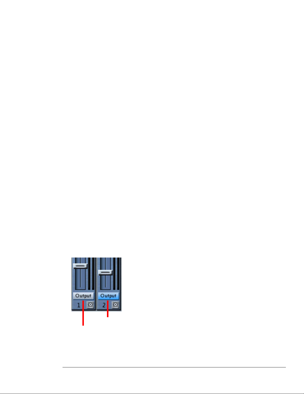
Use the Output Assignments panel to route the output of any channel to a particular hardware output or (for
Channels 1-16, and Effects Bus 1 and 2) to the Master channel bus. Output routings are displayed in a simple
grid, where a blue button indicates that an output is active and a white button indicates that an output is not
active.
Receptor’s 19 channels, consisting of instrument channels 1-16, Effects Bus 1 (B1), Effects Bus 2 (B2), and the
Master (M) channel appear in columns. All possible output routings appear in rows, and include:
• Master Bus - this is the default routing for the 16 instruments channels and two effects busses. When you
route a channel to the Master bus, it’s output signal appears on the output(s) assigned to the Master (M)
Channel. Click the Master Bus button beneath any channel number to turn the output on or off for that
channel.
• Analog L/R + ADAT 1/2 - The Analog L/R and ADAT 1/2 outputs are duplicated on Receptor. Whatever
appears on the analog output appears on the ADAT 1/2 output and vice-versa. Although you may route
any channel directly to this output, Receptor’s Master Channel is permanently routed to the Analog L/R +
ADAT 1/2 output. So, if you’re wanting to route some channels to separate outputs for submixing purposes,
you’ll probably want to choose another output pair. Click the Analog L/R + ADAT 1/2 button beneath any
channel number to turn the output on or off for that channel.
• ADAT 3/4 - You may route the output of any channel to ADAT 3/4. This is ideal if you wish to set up
separate submixes or apply external effects to one or more Receptor channels. Click the ADAT 3/4 button
beneath any channel number to turn the output on or off for that channel.
• ADAT 5/6 - You may route the output of any channel to ADAT 5/6. This is ideal if you wish to set up
separate submixes or apply external effects to one or more Receptor channels. Click the ADAT 5/6 button
beneath any channel number to turn the output on or off for that channel.
• ADAT 7/8 - You may route the output of any channel to ADAT 7/8. This is ideal if you wish to set up
separate submixes or apply external effects to one or more Receptor channels. Click the ADAT 7/8 button
beneath any channel number to turn the output on or off for that channel.
• S/PDIF L/R - You may route the output of any channel to the stereo S/PDIF output. This is ideal if you
wish to set up separate submixes or apply external effects to one or more Receptor channels. Click the
S/PDIF L/R button beneath any channel number to turn the output on or off for that channel.
To close the Output Assignments panel and keep your changes, click the Close button. To close the Output
Assignments panel and cancel all changes made since opening the panel, click the Cancel button. To reset all
Receptor channels to their default output assignments, click the Defaults button.
NOTE 1: The same Output Assignments panel opens no matter which channel’s Output Assignment Selector
you click. Opening the Output Assignments panel gives you a quick one-screen overview of Receptor’s entire
output configuration.
The Output Assignment Selector at the bottom of each panel has two color states. If the button is gray, it
means that the channel is set to its default output assignments. If the button is blue, it means you are currently
overriding the default output assignment for that channel.
Custom Output Routing
Default Output Routing
7: Graphic UI - Mix View 93 Receptor Manual
Page 94
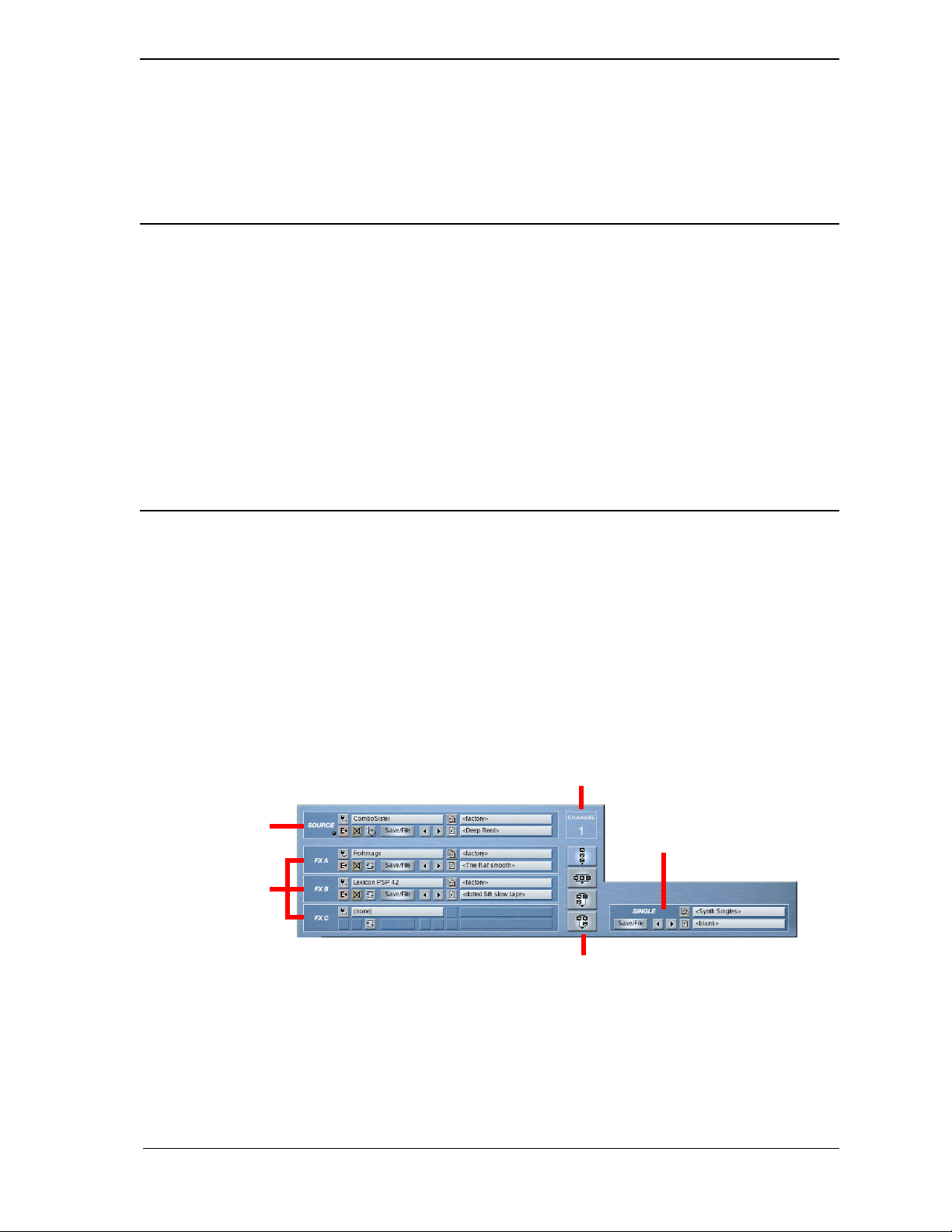
Channel Number
The channel number appears at the bottom of the channel strip. Instrument Channels are numbered 1-16. Effects
Busses are numbered B1 and B2 (for “Bus 1” and “Bus 2”). The Master output channel is labeled “M”, for
Master. These are the same numbers that appear in the top left corner of Receptor’s front panel LCD.
NOTE: By default, an instrument’s channel number is also its MIDI receive channel, unless you manually
override that value using the Source slot’s MIDI Filter Button (discussed later in this chapter).
Channel Bypass
Click the Channel Bypass button to bypass every plugin in that channel. When a channel is bypassed, it’s
Bypass button is yellow (as are the Bypass buttons for all plugins in that channel).
If the channel is already bypassed, then clicking the Channel Bypass button will un-bypass the channel and
every plugin in that channel.
The Channel Bypass button provides a quick and effective way to instantly regain all the CPU resources used
by a channel’s plugins, which can help when balancing Receptor’s processing needs.
POWER USER TIP: Channel Bypass is great for live performance. You could, for example, load a large Multi
patch with every instrument channel set to respond to the your MIDI controller’s MIDI transmit channel, and
with all but one instrument channel bypassed. You could then switch between patches (and synths) by bypassing
and un-bypassing instrument channels. Essentially, this gives you a very quick way to change patches in a live
situation, without recalling patches and waiting for a number of plugins to instantiate.
Channel Levels
The Channel Levels show the output volume of the Instrument channel. If a level has clipped, the red LED will
remain lit until cleared. You can clear the clipping indicator by clicking it.
NOTE: Watch these levels carefully! There can be quite a bit of signal level variation between different plugins.
Some boisterous plugins may clip the output levels at the channel’s default volume — others may have rather
subdued outputs.
Channel Details Overview
The top half of the Mix View windows shows the detailed plugin assignment parameters for the channel whose
Channel Selector button is currently glowing orange.
Source Slot
FX Slots
--- Channel Details Overview ---
Channel Number
Single Patch Slot
FX Routing
The following sections discuss the various Channel Detail parameters in depth.
7: Graphic UI - Mix View 94 Receptor Manual
Page 95
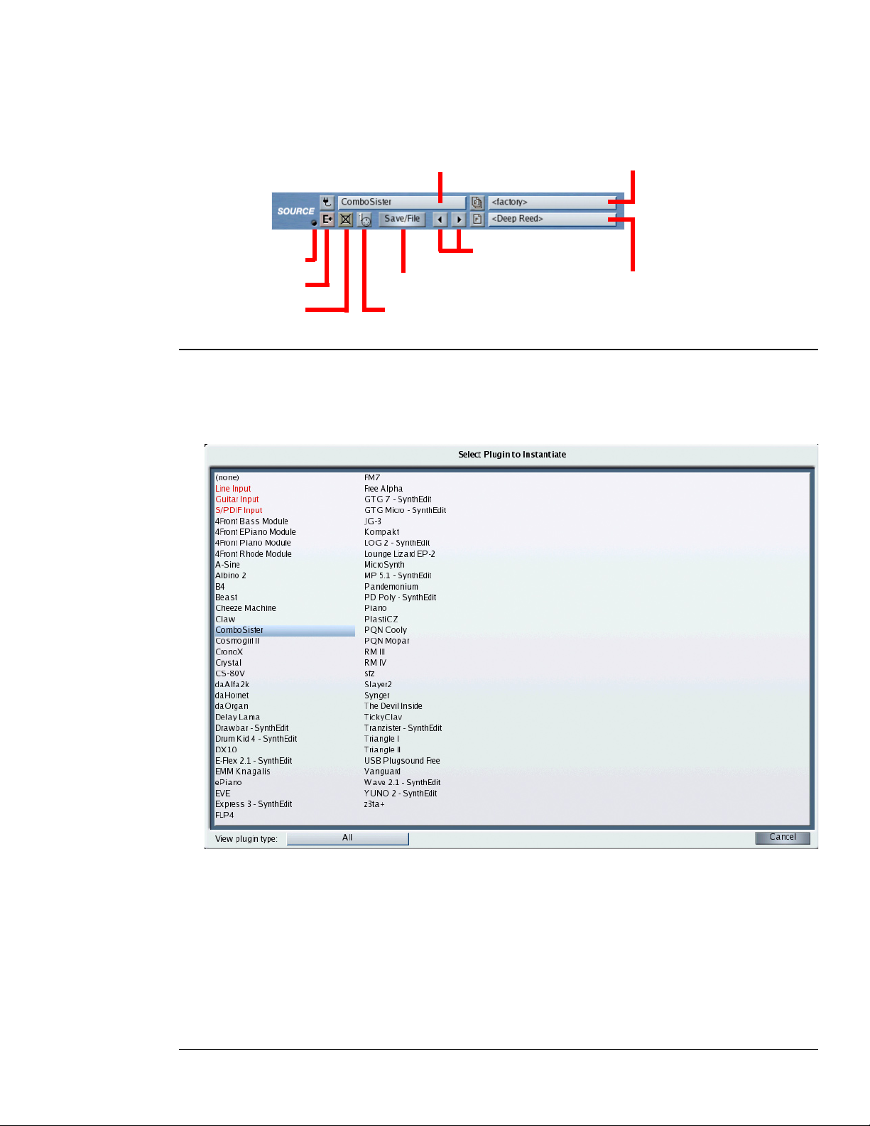
Source Slot Anatomy
These parameters are nearly the same as those accessed from the SOURCE button on Receptor’s front panel.
They define a channel’s audio source (either an external audio input or a VSTi) and, as such, are only available
in Instrument Channels. There are no Source Slots in either the Effects Bus or Master channels.
Bank Selector
Patch Selector
Output Level
Edit
Bypass
Source Selector
Prev/Next Patch
Save/File
MIDI Filter
Source: Source Selector
Click the Source Selector to open a pop-up panel of audio sources for the instrument. An audio source can
be either a VSTi (software plugin) or an external audio input. If you select a VSTi, Receptor instantiates that
plugin. If you select an audio input, Receptor uses the signal appearing at that input as the audio source.
Select the desired source from the pop-up Source panel to instantiate it. Sources appear in the list as follows:
• (none) - This option always appears on top. Selecting it uninstantiates a Source plugin. When you
uninstantiate a Source plugin, you automatically clear any FX instantiations used in the channel.
Essentially, (none) provides a shortcut for completely clearing an instrument channel.
• Audio Inputs - These always appear just below the (none) option and are shown in red, indicating that they
are audio input sources, not VSTi plugins.
• VSTi plugins - All VSTi plugins appear in alphabetical order. Some plugins may have a 2-character prefix
contained inside a square bracket. This prefix, described a bit later, does not alter the display order of
plugins.
7: Graphic UI - Mix View 95 Receptor Manual
Page 96

If you wish to limit the number of plugins in the list, you can view only those plugins of a particular type.
Click the “View plugin type” menu to select whether you want to see all available plugins, or just those from a
particular manufacturer. You can also choose to view only the available audio inputs. If more than 128 plugins
are currently available, then NEXT PAGE and PREVIOUS PAGE icons will appear at the bottom of the Plugin
Select panel. Use these to view the next or previous set of 128 plugins.
Some plugins may have bracketed prefixes before their names. Here’s what they mean:
• [##] - This means that a demo version of the plugin is currently installed and that, by instantiating it, you
will activate its demo period.
• [nn] - In this case, nn = some number, such as 17, or 03, or 11. This means that the plugin is currently
running in demo mode and this prefix shows you how many days remain in your demo period.
• [--] - This means that the installed plugin must be purchased in order to be instantiated. You will see this
symbol when a demo period has expired or if no demo is available for a particular plugin. Also, when you
turn on Receptor, your iLok is scanned for licenses after the unit starts up. Because of this, it’s possible that
plugins you have purchased will display the [--] prefix for the first couple of minutes. Don’t worry. Your
purchased premium plugins will still instantiate if selected. It just takes a couple of minutes for Receptor to
scan all the plugins and update their prefix display, which it does in the background so that Receptor will
start up as quickly as possible.
• [??] - This means that an error is preventing you from instantiating this plugin. In most cases, it appears
because the iLok is not inserted into Receptor properly.
• [XX] - This means that the plugin is no longer on Receptor’s hard drive. Obviously, this will only appear if
you have loaded a Single or Multi patch that references a plugin no longer on Receptor.
• No Prefix - If there is no prefix before a plugin name, that means it’s either a free plugin or a premium
plugin that you have purchased.
Source: Bank Selector
The Bank selector is available only if you selected a VSTi in the Plugin selector. It will not appear if you select
an audio input for the source.
Click the Bank Selector to open the Load Panel to its Bank List view. The bank you select determines the list of
patches that appear in the Load Panel’s Patch List.
In general, select the desired bank from the Load Panel, then click the Load Panel’s Patch tab to select a patch to
load from within that bank. For detailed information about loading banks and patches, see Chapter 10, “Graphic
UI - Loading Patches”.
SHORTCUT: When the Load Panel is open, press CTL-TAB to switch back and forth between the Bank and
Patch tabs without using the mouse.
Source: Patch Selector
The Patch selector is available only if you selected a VSTi in the Plugin selector. It will not appear if you select
an audio input for the source.
Click the Patch selector to open the Load Panel to its Patch List view. The Patch List contains the names and
numbers of all 128 patches stored within the current bank.
In general, select the desired patch from the Patch List and close the Load Panel when you’re finished. For
detailed information about loading banks and patches, see Chapter 10, “Graphic UI - Loading Patches”.
The patch selector shows the name of the current patch. If a patch has been modified since it was loaded from
disk, its name is italicized.
SHORTCUT: When the Load Panel is open, press CTL-TAB to switch back and forth between the Bank and
Patch tabs without using the mouse.
7: Graphic UI - Mix View 96 Receptor Manual
Page 97

Source: Prev/Next Patch Buttons
The button with the left-pointing arrow selects the previous patch in a patch list without having to open the
patch panel. The button with the right-pointing arrow selects the next patch in a patch list without having to
open the patch panel.
NOTE: If you’re currently displaying the last patch in a bank and you click the Next button, Receptor will load
the first patch in the following Bank. Similarly, if you’re currently displaying the first patch in a bank and you
click the Prev button, Receptor loads the last patch in the previous bank. In other words, it’s possible to use the
Prev/Next buttons to step through every patch, no matter how many banks are associated with a plugin.
Source: Bypass Button
Click this button to bypass the instrument slot. An instrument slot is bypassed when the button is bright
yellow. In addition, all text in a bypassed slot appears grey, further indicating that it’s bypassed. Bypassing an
instrument mutes that instrument and releases the CPU resources required to run it. Bypass is useful whenever
Receptor’s CPU resources are maxed out and you want to disable a particular plugin.
NOTE: If you bypass an Instrument whose Source is set to one of the audio inputs, then the audio input is
muted, but no significant amount of CPU resources are saved (since routing audio uses much less processor
than instantiating a VSTi).
Source: MIDI Filter Button
This button opens the corresponding channel’s MIDI Filter panel and displays some information about the state
of that filter. Specifically:
• The number on the button displays the MIDI Filter panel’s Listen to MIDI Channel value. By default, this
number equals the Instrument Channel number and appears in white text. If you override the value in the
MIDI Filter panel, the text will be yellow.
• The button color indicates whether or not any MIDI filtering is applied.
Gray button = NO MIDI Filtering is active
Blue button = MIDI Filtering is active
If the button is gray, then no MIDI filtering is applied and every parameter in the MIDI Filter panel is
set to its default state. If the button is blue, then some form of MIDI filtering is in effect (meaning some
parameter in the MIDI Filter panel is set to something other than the default value.
7: Graphic UI - Mix View 97 Receptor Manual
Page 98
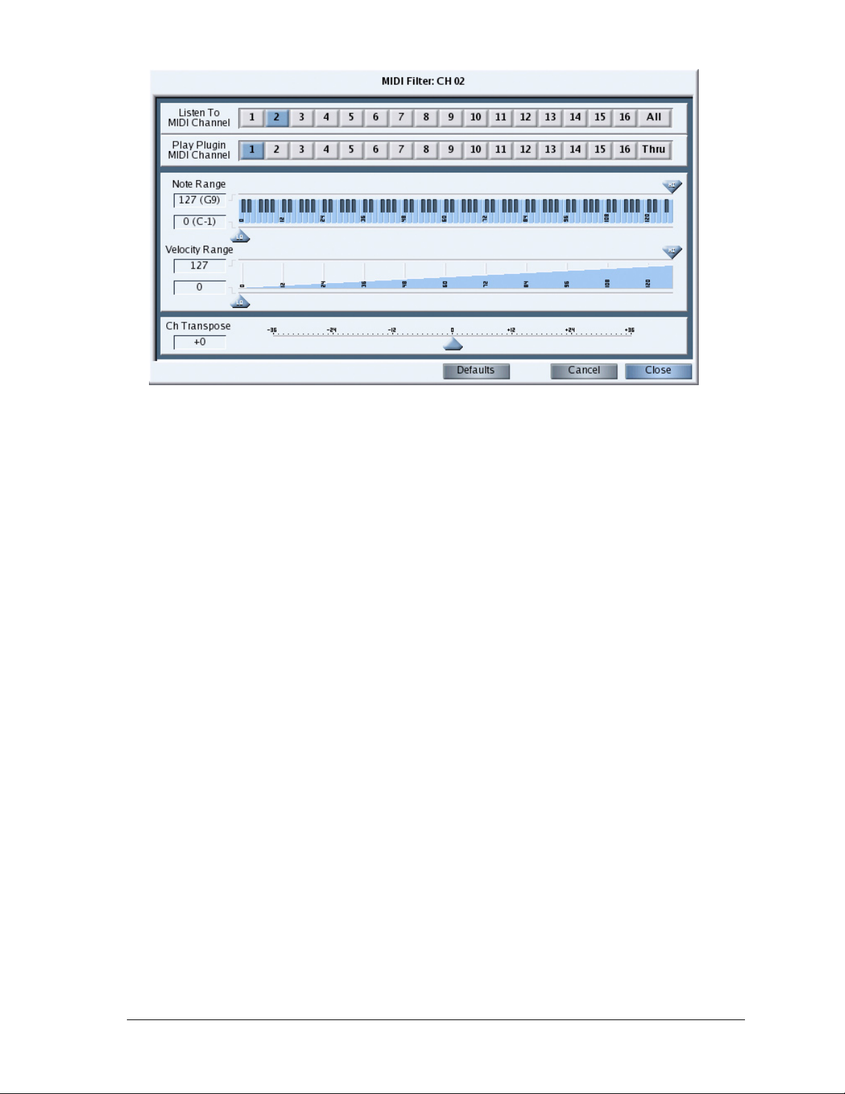
Click the MIDI Filter button to open the MIDI Filter panel for that channel.
--- MIDI Filter Panel ---
The MIDI Filter panel is used to re-channelize, remap, and filter the MIDI data used to control a particular
Receptor channel. From top-to-bottom, the MIDI Filter panel contains the following elements:
• Listen To MIDI Channel
• Play Plugin MIDI Channel
• Note Range
• Velocity Range
• Ch Transpose
The following sections discuss each of these elements in detail.
Listen to MIDI Channel
Use this section to tell Receptor which MIDI channel to route to the selected VSTi. By default, an instrument
channel listens to the like-numbered MIDI Channel. For example, the VSTi you instantiate on Instrument
Channel 6 would respond to data coming in on MIDI channel 6. In general, you will change this default
mapping whenever you want to stack two or more VSTi’s on the same MIDI channel (to create either layered
sounds or split keyboards).
For example, you might want to instantiate an analog synth on Instrument Ch 1 and a string synthesizer on
Instrument Ch 2, but play them simultaneously from your keyboard to create a thicker, richer sound. To do this,
you would set the source on Instrument Channel 2 to listen to MIDI Ch 1. Now, when you play your MIDI
keyboard using MIDI Ch 1, Receptor plays both the VSTi assigned to Instrument Ch 1 and the one assigned to
Instrument Ch 2.
You can choose between MIDI channels 1-16, or you can choose ALL, which means that the VSTi receives
MIDI data from any and all MIDI channels.
The MIDI Filter button shown in Mix view always displays the Listen to MIDI Channel value.
NOTE: The Listen to MIDI Channel setting only changes the MIDI channel used to control the sound being
produced by an instantiated VSTi. It does not re-channel the data used to control the Instrument’s Mixer
Channel (such as Volume, Pan, Effects Send Levels, and so on). For example, if you instantiated a VSTi on
Instrument Channel 2, but told it to receive on MIDI Ch 1, the VSTi would respond to note, pitch bend, mod, and
sustain pedal data on MIDI channel 1, but the Instrument Channel’s volume, pan, effects send levels, and so on
would still respond to MIDI channel 2. This allows you to separately address and mix Receptor’s 16 instrument
channels, even though some of them may use layered or zoned instruments.
7: Graphic UI - Mix View 98 Receptor Manual
Page 99

Multitimbral Synth Tip: Note that the Listen to MIDI Channel and Play Plugin MIDI Channel settings, when
used together, let you play multiple channels on a multitimbral VSTi. If you instantiate a multitimbral VST and
assign its LISTEN TO value to ALL and its PLUGIN CH value to THRU, then every incoming MIDI channel
will be thru’d to the like-numbered VST channel, allowing for multitimbral operation of that VST.
Play Plugin MIDI Channel
Use this section when a plugin needs to play on a particular MIDI channel regardless of what MIDI channel is
used to trigger it.
By default, this parameter is always set to 1, meaning every instantiated instrument plays whatever sound
is assigned to it’s internal definition of channel 1. In general, you will not need to change this default MIDI
channel mapping since the majority of VSTi’s are monotimbral and will respond the same no matter which
MIDI channel you use to play them.
A small number of VST instruments (such as Native Instruments’ B4) respond differently depending on which
MIDI channel you play them on. For example, B4’s upper manual is hardwired to MIDI Ch 1; its lower manual
to MIDI Ch 2; and its pedals to MIDI Ch 3. If, for example, you instantiated the B4 on Instrument Channel
7, you would hear its upper manual play (since all plugin channels are, by default, remapped to Ch 1). If you
actually wanted to play the lower manual, you would set the Play Plugin MIDI Channel value to 2 so that the
incoming MIDI data would be routed to B4 Channel 2, which is the lower organ manual.
In addition, some VST instruments are multitimbral and may therefore have different sounds assigned to
different MIDI channels. Most of these multitimbral instruments will work flawlessly with MIDI channel 1,
which is why this is the default value. However, the Play Plugin MIDI Channel parameter lets you control any
plugin channel you wish, regardless of which Instrument Channel you used to instantiate the plugin, or which
incoming MIDI Channel it listens to.
You can choose between MIDI channel 1-16, or you can choose THRU, which means that the VSTi plays on
the same MIDI channel set in the Listen to MIDI Channel column.
7: Graphic UI - Mix View 99 Receptor Manual
Page 100
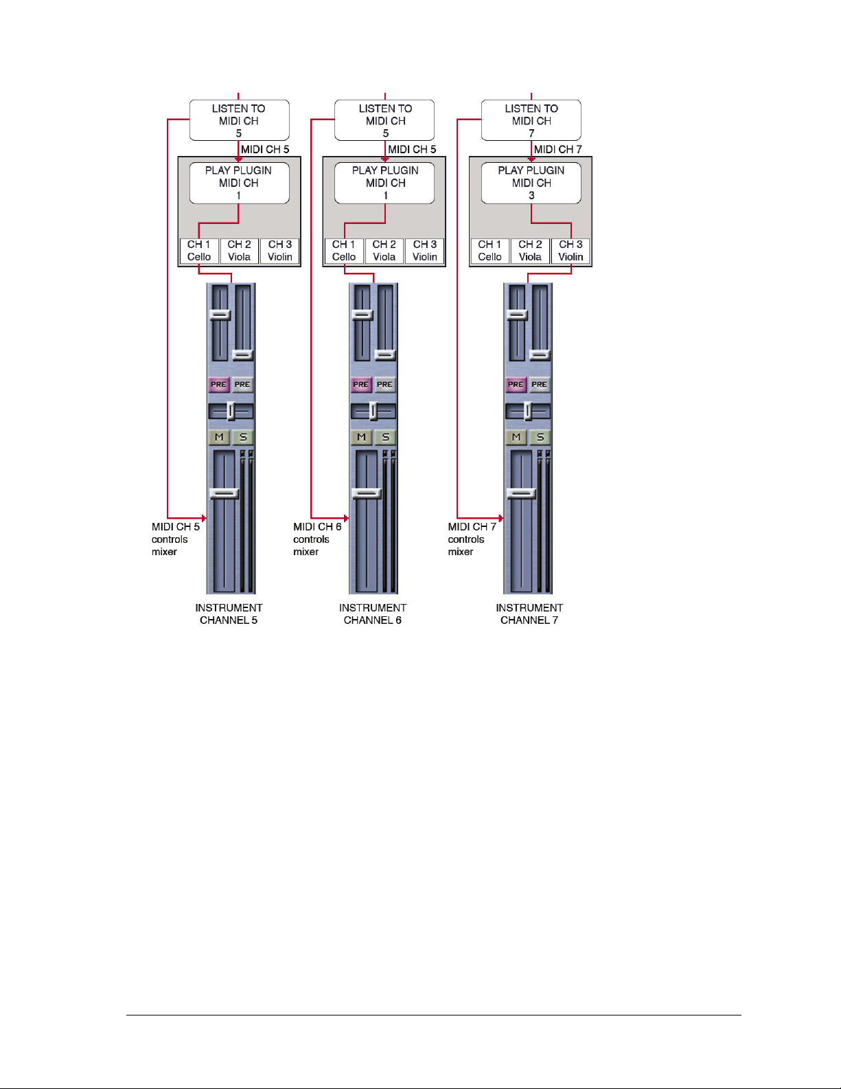
The following examples may help you better understand the correlation between Receptor and the Listen to
MIDI Channel and Play Plugin MIDI Channel settings.
--- Remapping Examples ---
The previous figure shows three different Instrument Channels, numbers 5-7. Each Instrument Channel has an
identical multitimbral VSTi instantiated as its Source. Let’s look at the three examples one-at-a-time:
• Instrument Channel 5: This Instrument Channel is using the default values for both the LISTEN TO and
PLUGIN CH options. In this example, any note and performance data that Receptor “hears” on MIDI
CH 5 will be used to play the VSTi (as set by the LISTEN TO parameter). Similarly, any MIDI data
arriving on MIDI CH 5 will also be used to control the Instrument Channel’s mixer parameters. Because the
multitimbral VSTi is being told to use Ch 1 (the PLUGIN CH parameter), a Cello sound is actually heard.
• Instrument Channel 6: This Instrument Channel is using the default PLUGIN CH value and a custom
LISTEN TO value. In this example, any note and performance data that Receptor “hears” on MIDI CH 5
will be used to play the VSTi (as set by the LISTEN TO parameter), however the Instrument Channel’s
mixer parameters are actually controlled by MIDI Channel 6 (The Instrument Channel number). Because
the multitimbral VSTi is being told to use Ch 1 (the PLUGIN CH parameter), a Cello sound is actually
heard.
• Instrument Channel 7: This Instrument Channel is using the default value LISTEN TO value and a custom
PLUGIN CH value. In this example, any note and performance data that Receptor “hears” on MIDI CH
7 will be used to play the VSTi (as set by the LISTEN TO parameter). Similarly, any MIDI data arriving
on MIDI CH 7 will also be used to control the Instrument Channel’s mixer parameters. Because the
multitimbral VSTi is being told to use Ch 3 (the PLUGIN CH parameter), a Violin sound is actually heard.
7: Graphic UI - Mix View 100 Receptor Manual
 Loading...