

Murzan PI-50 Service Manual
UNIT SERIAL NUMBER
IMPORTANT DOCUMENTATION, DO NOT DISCARD
CE DECLARATION OF CONFORMITY AVAILABLE
OPERATION & SERVICE MANUAL
MURZAN PI-50 PUMP
123A
MURZAN INC.
2909 LANGFORD RD. 1-700
NORCROSS, GA 30071
UNITED STATES OF AMERICA
TEL: (770) 448-0583 FAX: (770) 448-0967
MURZAN SERIAL NUMBER
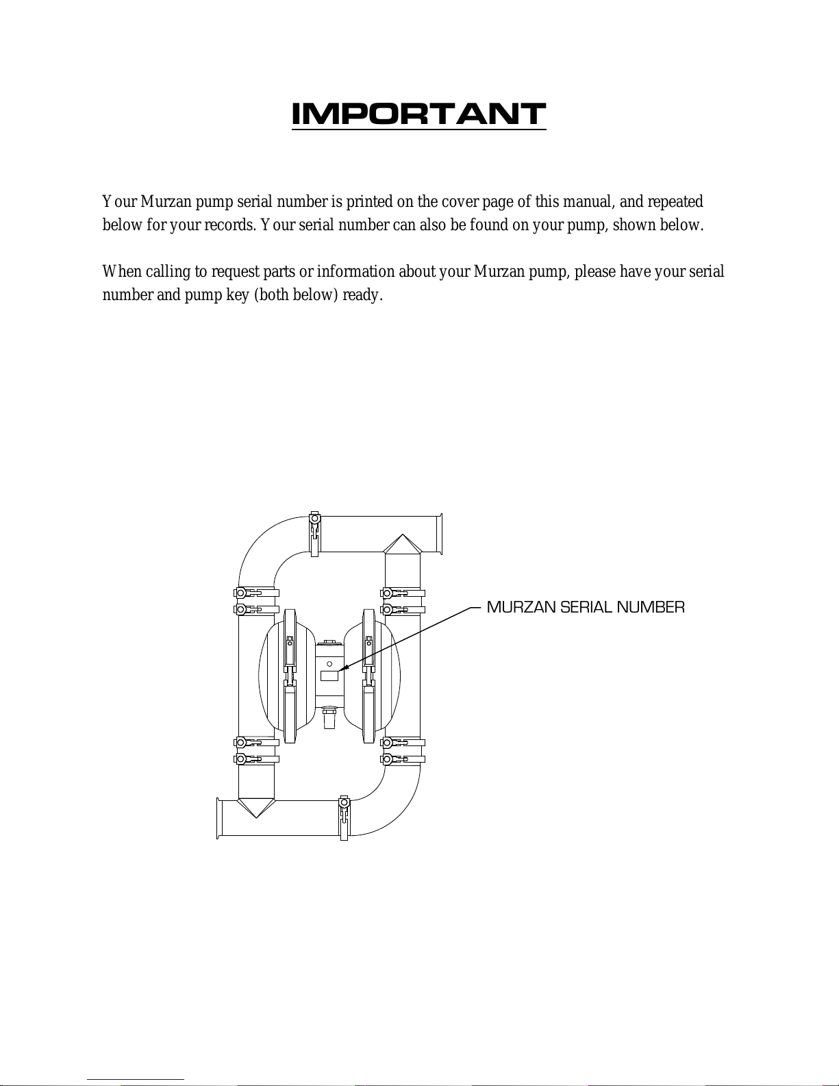
IMPORTANT
Your Murzan pump serial number is printed on the cover page of this manual, and repeated
below for your records. Your serial number can also be found on your pump, shown below.
When calling to request parts or information about your Murzan pump, please have your serial
number and pump key (both below) ready.
Serial number: 123A
Pump key: PI-50 - SL - V - HV MC - IB3 - 3Mx3M - FG/TF/FG - BDA - HT - S

TABLE OF CONTENTS
1.0 Air Quality .............................................................................................................................. 1
2.0 Basic Operation ....................................................................................................................... 2
3.0 Maintenance and Cleaning ...................................................................................................... 3
3.1 Clean In Place ................................................................................................................... 4
4.0 Pump Subassemblies ............................................................................................................... 5
4.1 Center Subassembly .......................................................................................................... 8
4.2 Chamber Subassembly .................................................................................................... 10
4.3 Check Valve Subassembly .............................................................................................. 12
4.4 Manifold Subassembly .................................................................................................... 14
5.0 Pump Disassembly ................................................................................................................ 16
5.1 Assembly A ..................................................................................................................... 19
5.2 Assembly B ..................................................................................................................... 21
5.3 Assembly C ..................................................................................................................... 23
6.0 Pump Reassembly ................................................................................................................. 25
7.0 Troubleshooting .................................................................................................................... 29
8.0 Spare Parts ............................................................................................................................ 30
9.0 Terms of Sale ........................................................................................................................ 31
10.0 Additional Documents ........................................................................................................ 32
1.0 AIR QUALITY
Your Murzan Pump is powered with compressed air at a maximum pressure of 100 PSIG. DO
NOT EXCEED THIS LEVEL, as damage to the system or personal injury may occur.
Murzan pumps use a non-lubricated air valve system to meet the stringent USDA and FDA
standards required for pneumatically operated diaphragm pumps in the food and pharmaceutical
industries. Only a Murzan pump gives you this unique feature.
Murzan pumps have been engineered to provide the highest standard of performance and
reliability in handling your sanitary products. We at Murzan insure the most hygienic system
possible by equipping all Murzan pumps with an oil free, non-lubricated air valve. The patented,
non-lubricated Murzan air valve does not exhaust contaminated oil vapor into your plant
environment, unlike a lubricated air valve. A clean, well-filtered air supply is essential for the
proper operation of the air valve and for the prevention of contaminants being expelled into the
plant environment. A dirty oil laden air supply is by far the most expensive and overlooked
problem we find in working with our customers.
Oil and other contaminants that enter the pump drastically reduce the life of the air valve, shaft
bushing assembly, shaft, and block gaskets. The results are a much higher frequency of parts
replacement and repair, with a corresponding increase in maintenance expenses. As pump parts
become worn due to contamination, the pump looses efficiency and requires increased air
volume to move the product. This puts additional strain on the air supply and brings increasing
amounts of oil to the pump. The use of filters will pay for themselves in a very short time
through reduced parts usage and maintenance man hours.
1
2.0 BASIC OPERATION
Your Murzan Pump has wetted parts constructed of 304 or 316 stainless steel and FDA approved
elastomers.
When using the pumps in a permanent installation attached to rigid piping, the use of flexible
couplings on both the suction and discharge ports of the pump is recommended to reduce
vibration due to the reciprocating nature of the pump.
All fittings must be tight in order to eliminate air and product leaks. This will allow the pump to
run as efficiently as possible.
The suction pipe diameter should never be less than the diameter of the suction manifold. Larger
diameters may be used if extremely viscous materials are to be pumped.
Non-collapsible reinforced hose must be used on the suction side of the pump if hoses are to be
used in place of piping.
Should you need to control your pump discharge rate, you may do so by:
1. Limiting the volume and/or pressure of the air supply to the pump. An air regulator
installed at the air inlet will serve this purpose.
2. Throttling the pump discharge by installing a valve in the discharge line of the pump.
When the discharge pressure equals or exceeds the air supply pressure, the pump will
automatically stall, eliminating the need for pressure relief valves. Pump damage will not
occur when the pump is stalled.
Caution: Do not exceed 100 psig air supply pressure.
Caution: Maximum temperature limits are based upon both mechanical and corrosive
factors. Certain products will significantly reduce maximum safe operating temperatures.
Please consult the factory when product compatibility is in question.
2
3.0 MAINTENANCE & CLEANING
In general, cleaning requirements and guidelines are set by governmental agencies such as the
USDA or FDA in the United States. Each user of Murzan Inc. equipment is responsible for ensuring
that their cleaning process and procedures meet the applicable governmental and industry standards.
Murzan Inc. makes every effort to provide equipment that will easily meet governmental cleaning
requirements and facilitate internal and external cleaning processes for the customer. However,
strict compliance with governmental regulations regarding specific processes and suitable chemicals
is the sole responsibility of the customer.
Your Murzan pump consists of two types of parts: wet parts and dry parts.
Wet parts are those that come into contact with the product being pumped; dry parts are those that
do not come into contact with the product being pumped.
Wet parts require regular and thorough cleaning. It is strongly recommended to clean all wet parts
after every use of your Murzan pump. Throughout the life of your Murzan pump, all non-stainless
steel wet parts will require replacement as they wear out with use/time. Refer to section 5.0 on
Pump Disassembly with instructions for cleaning the wet parts of your Murzan pump. Additionally,
refer to section 8.0 on Spare Parts for more details.
Dry parts require routine inspection and some parts require replacement at recommended intervals
of 6 to 12 months. Refer to section 5.0 on Pump Disassembly with instructions for cleaning the dry
parts of your Murzan pump. Additionally, refer to section 8.0 on Spare Parts for more details.
3
3.1 CLEAN IN PLACE
Most plants have their own guidelines for Clean In Place (CIP). Please follow your plant’s
requirements.
If you are cleaning your Murzan pump along with your piping system at the same time, a bypass
hose should be used to provide the additional flow required. It is recommended that the minimum
flow rate for CIP of your Murzan pump be 5 ft/sec (1.5 m/s). Please refer to the CIP Diagram in
section 10.0.
4
4.0 PUMP SUBASSEMBLIES
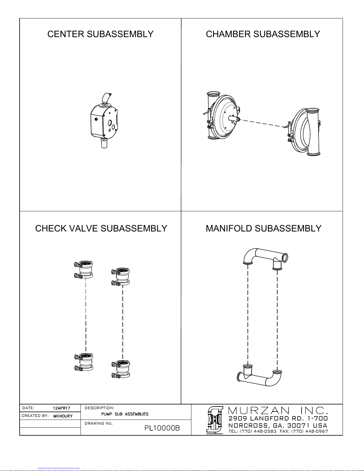
The diagrams on the following two pages identify the four subassemblies that make up your
Murzan Pump: the center subassembly, the chamber valve subassembly, the check valve
subassembly, and the manifold subassembly. The first diagram shows the four individual
subassemblies, and the second diagram shows the complete Murzan pump assembly (exploded
view).
Note: the manifolds, check valves, and chambers on the following page may be different than
those of your pump. However, the four main subassemblies remain the same for any Murzan
pump.
The tables and diagrams in sections 4.1-4.4 give detailed listings of the respective subassembly
components, specific to your Murzan pump. These listings will aid in identifying components
for operation, cleaning, maintenance and servicing.
5
2909 LANGFORD RD. 1-700
NORCROSS, GA. 30071 USA
TEL: (770) 448-0583 FAX: (770) 448-0967
DATE:
DRAWING No.
DESCRIPTION:
CREATED BY:
CENTER SUBASSEMBLY CHAMBER SUBASSEMBLY
CHECK VALVE SUBASSEMBLY MANIFOLD SUBASSEMBLY
6

2909 LANGFORD RD. 1-700
NORCROSS, GA. 30071 USA
TEL: (770) 448-0583 FAX: (770) 448-0967
DATE:
DRAWING No.
DESCRIPTION:
CREATED BY:
PUMP ASSEMBLY
7
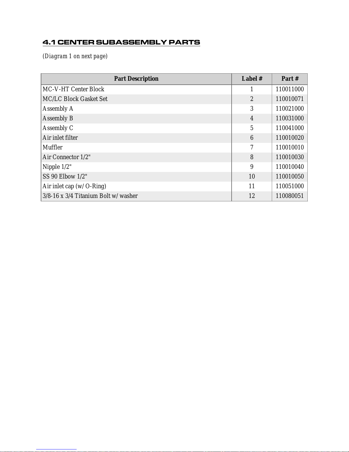
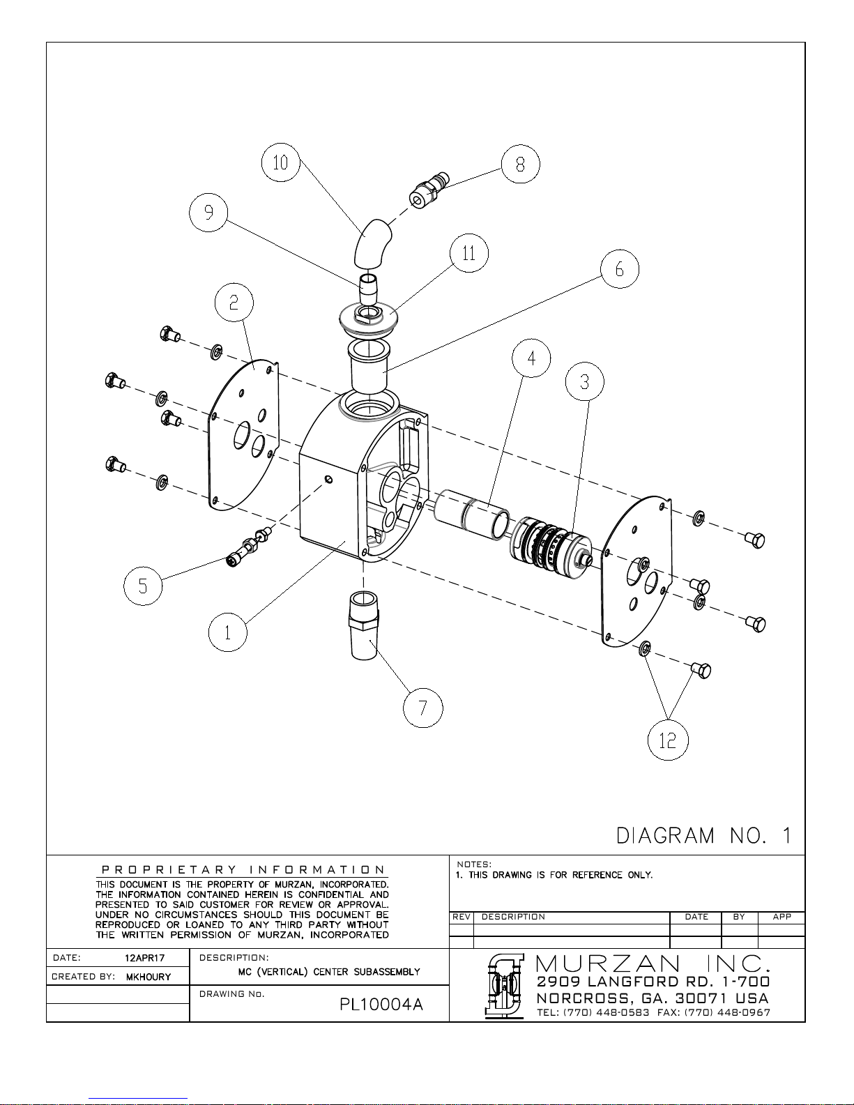
4.1 CENTER SUBASSEMBLY PARTS
(Diagram 1 on next page)
Part Description Label # Part #
MC-V-HT Center Block 1 110011000
MC/LC Block Gasket Set 2 110010071
Assembly A 3 110021000
Assembly B 4 110031000
Assembly C 5 110041000
Air inlet filter 6 110010020
Muffler 7 110010010
Air Connector 1/2" 8 110010030
Nipple 1/2" 9 110010040
SS 90 Elbow 1/2" 10 110010050
Air inlet cap (w/ O-Ring) 11 110051000
3/8-16 x 3/4 Titanium Bolt w/ washer 12 110080051
8
2909 LANGFORD RD. 1-700
NORCROSS, GA. 30071 USA
TEL: (770) 448-0583 FAX: (770) 448-0967
P R O P R I E T A R Y I N F O R M A T I O N
DATE:
DRAWING No.
DESCRIPTION:
REV DESCRIPTION
NOTES:
BY APPDATE
CREATED BY:
9
 Loading...