

Page 1

Test Chest: Manual
Murraypro
Test Chest
+
EYE~POD
Operational Manual
Issue: 1V0
Page 2
Test Chest: Manual
Test Chest
Manual 1V0
Congratulations on the purchase of your Murraypro Test Chest
We are certain you will find this to be an extremely quick to use, and
powerful diagnostic Tool. It will become a truly indispensable item in your daily work
on the Bench, or whilst away elsewhere investigating problems under battery power.
Test Chest is an impressive Product, so let’s spend a few moments together
getting to know it, and exploring it’s features. In fact of course, most of the major
features are immediately obvious as they are menu selected, but other rather more
subtle features may be a key press or two away. Users who wish to get the most out
of the Test Chest are recommended to familiarise themselves with the contents of
this Manual, and the Unit itself, before attempting serious operational use of the
instrument in the Field. We offer a short demo Video showing many features:http://www.murraypro.com/testchest3g.htm
Introduction:
Test Chest is controlled by means of a touch sensitive LCD panel and only a
gentle touching action will be required to achieve the desired action. The LCD's
surface must NEVER be activated by a stylus such as a capped ball-pen, or, worse
still, a hard point such as an uncapped pen or a screwdriver! Such activity is highly
likely to cause scratch-damage to the LCD's front panel; physical damage of this sort
is specifically excluded from warranty cover, and LCD replacements due to this
cause will be chargeable.
Ensure that the ‘Battery Off/Norm’ switch, situated on the left end panel,
is in the ‘Norm’ position, and 'Power up' is initiated by just lightly tapping
the LCD panel anywhere, with the flesh of a finger. Next, ‘confirm’ this
'power-up?' command with a light tap on the Switch Icon itself within 4
seconds. Major functions are then selected and initiated by tapping the required
menu function from the 'Home Menu' page, which is presented immediately after the
Test Chest power-up confirmation. In a number of instances, Test Signal Generation
and the Wave-Form display mode, for example, selection of the required output Test
Signal or WFM display mode, will require a subsequent selection process, via a submenu. This direct switching process is highly intuitive, and extremely quick to
implement. There is no place on Test Chest for assignable 'Hot Keys' or anything of
that nature. Often use of such key functions are very difficult to track, as the required
'next' function's position changes as each new menu page is presented!
Users should be aware that some Menu options, although subtle, will
substantially alter the mode of operation. As may be appreciated from
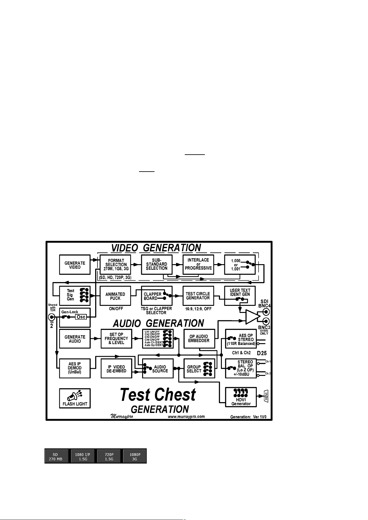
the Test Chest’s “Video Generation” flow chart, selecting 'Clapper
Board' for example, will bypass most other Video selections; whilst
selecting 'OUT~LOOP' bypasses the local TSG, forcing the output to be
a reclocked & equalised ‘LOOP’ of the input signal..... naturally, this can
only occur if a signal is actually present at the input!
Page 3
Test Chest: Manual
Selection of one of these powerful modes, whilst quite normal, could have a
high nuisance value' if unintentional, and so the TC will helpfully flag up such an
activation with a cautionary yellow coloured icon, or legend.
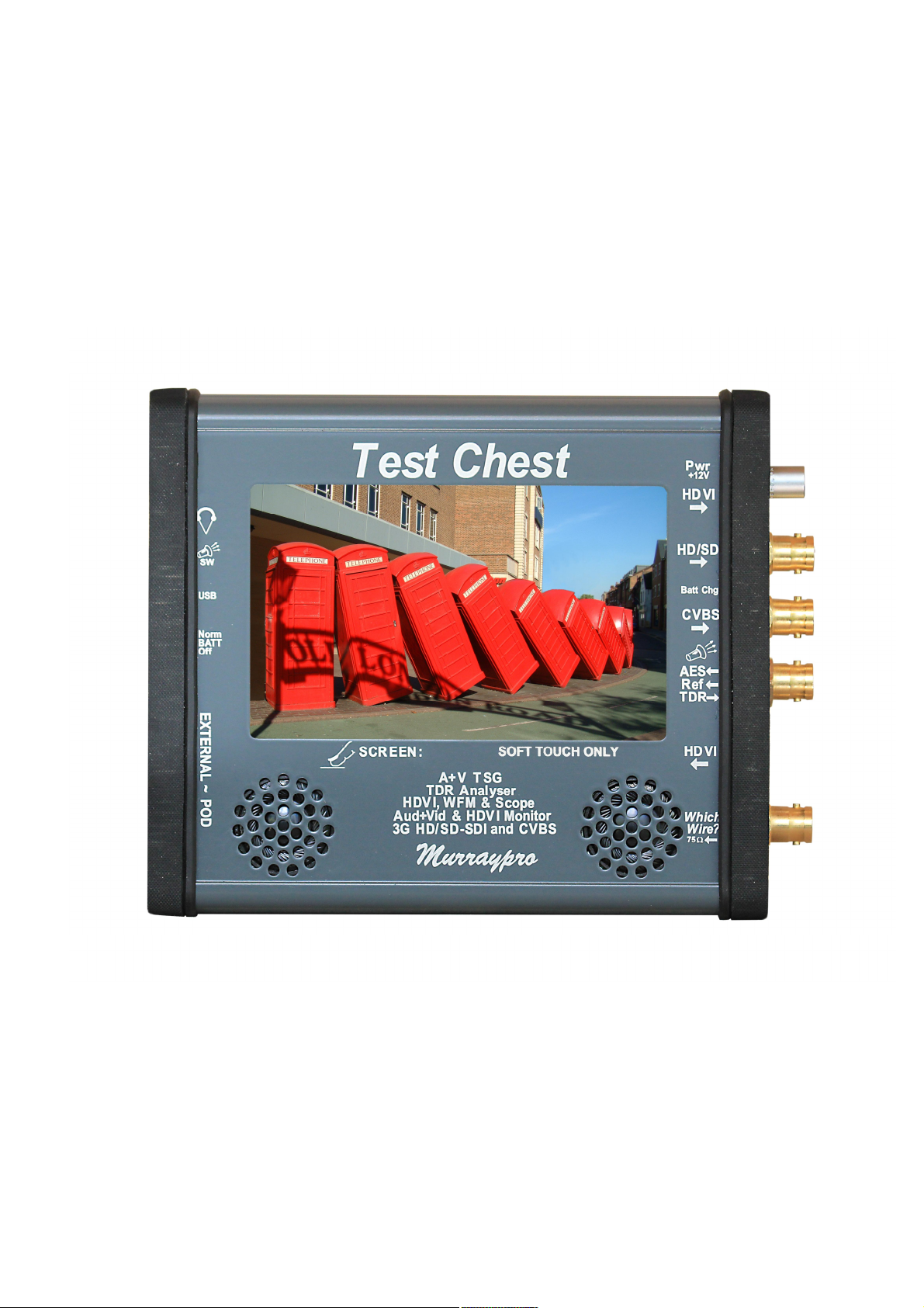
The cluster of 4 BNCs on the right side of the front panel carry Video input
and outputs. Unbalanced AES and External sync is input on BNC2, whilst the TDR
cable-test also shares this Port.
Balanced stereo audio input and output, together with the balanced AES OP,
are carried by the D-25F connector on the left panel which couples with the
“Audio~POD” breakout adapter. The 3.5mm Headphone Jack is located here too.
Test Chest: Front.
Power considerations.
Test Chest is powered when portable, from an internal 3000mAH 7V2 Lithium
Polymer battery pack. We have achieved nearly 5 hours endurance with a freshly
charged battery in tests, so realistically Users could anticipate in excess of three
hours operation. Power drain will be dependent to some extent upon LCD back light
Page 4
Test Chest: Manual
brightness, the mode used, and the Clock rate of the TV Standard.
Test Chest is unusual in that it has two quite distinct modes of operation, and
these are totally different, and separate, from any battery charging considerations:-
a) In Which-Wire? mode, the unit will detect an input signal on BNC1, and
power up automatically, displaying the signal as soon as it is detected. NO action
being required from the User, other to plug the unknown source into BNC1.
In “W-W?” mode, TC will automatically power down a moment or two after the
input signal is removed from BNC1. 'Touching' the LCD panel will end the “W-W?”
mode, and manual 'power down' will be required to restore “W-W?” mode.
b) In the Generation and Measurement modes, it will be necessary to turn the
Unit ON manually. This is achieved gently tapping the LCD panel, and
CONFIRMING your 'power on' request by tapping the Switch ICON presented in the
bottom-right of the LCD. In these modes, the Test Chest is 'powered down' by briefly
tapping the YELLOW switch icon on the menu home page.
Test Chest provides essentially 9 functions, which are described
more fully later, but these are at present, perhaps, best initially
considered under 3 major separate function headings:-
Page 5
Test Chest: Manual
1) Which-Wire?
Which-Wire? is an exceptionally powerful investigative tool in which Test
Chest emulates our earlier Murraypro 'Which-Wire?' Unit, and it is not even
necessary to ‘manually’ power the Unit up for operation in this mode. As soon as a
signal is applied to the 'Which-Wire?' input Test Chest automatically awakens,
determines it’s signal format, automatically selecting the optimum manner to display
the detected signal, whether it be TV monitor, WFM, or as an audio histogram.
Additionally if a TV signal is detected, it identifies the source's TV Standard as 3GSDI, HD-SDI, SD-SDI, CVBS, together with it's Frame Rate, which is reported on a
Banner at the top of the 16:9 LCD screen.
“W-W?” capability includes 'Tri-Level' and
'Colour Black' Sync detection. Either sync signal is
displayed in the WFM's 'H Expand' mode.
“W-W?” capability on BNC1 includes the
detection of UNBALANCED AES and SPDIF sources.
When present, the LCD display automatically selects
AES mode on the 'Audio Monitoring' page.
“W-W?” detection mode has been extended to now
include High Definition Video Interface sources which are applied
to the connector twixt BNC1 & 2. When detected, HDVI images
@ TV related scan rates will be displayed, sources on other
standards will be detected, but may not be coherently presented.
Users should connect their 'mystery IP signal' to the lowest BNC connector,
BNC1, designated “WW?” at the bottom right of the front panel. This connector
always terminates the input with 75W, so it is never necessary to provide a separate
external termination. The fundamental feature of Which-Wire? Mode is that CVBS,
SDI and AES signals enter the Unit via the same connector. It is never necessary to
double guess what signal may be present on a given cable, as the Test Chest will
automatically switch to the appropriate Digital, Analogue, AES or Tri-level/Composite
sync mode, as required to correctly display the detected input which now includes
HDVI signals with TV related image formats.
It is vital to appreciate that “Which-Wire?” mode can ONLY be initiated with
the Test Chest un-powered, it cannot function when the Test Chest is already
powered up as it will already be in a ‘manually’ selected operating mode!
Following a ‘manual’ power-up, the main menu is presented from which the
User selects ‘TV’, WFM’ or ‘Audio’ mode as required. ~ Let us assume ‘TV’ mode is
manually selected, so applying a TV signal to the “W-W?” input will indeed display
an immediate picture, and in fact this will be even faster than from quiescent, as the
Unit is already powered, BUT it can’t identify Tri-level sync, or AES audio for
example, nor display these in any meaningful manner in TV Monitor mode, as this
doesn’t offer any 'WFM display' or AES measurement capability!
Page 6
Test Chest: Manual
This powerful “Which-Wire?” auto-detection feature is an important and vital
difference pioneered by Murraypro which completely separates Test Chest from
any other product. Other testers will require Users to consecutively, and tediously,
offer an unknown signal to the separate SDI, CVBS and AES inputs in turn; if indeed
they actually possess any analogue capability at all! Consider for a moment, just how
does one investigate and resolve a Station Reference Pulse problem without any
analogue capability?
AES inputs in “Which-Wire?” mode.
Be aware that Test Chest’s highly impressive capability of detecting and
identifying “AES” signals fed in via BNC1, ONLY applies when the Unit is in
“Which-Wire?” mode, having powered itself up automatically.
It most certainly does NOT apply when the Unit has been manually powered,
or if the “W-W?” mode has been manually over ridden with a subsequent 'touch'
command. Under these powered conditions it is necessary to apply the unbalanced
AES source directly to BNC 2, the normal AES IP port, and which is labeled as such.
Under all 'powered' modes use of BNC 2 as the AES input port is mandatory.
AES signals manually presented to the “Video” port BNC1, will NOT be recognised.
2a) Test Signal Generation ~ Video
TSG.
The Test Chest contains a powerful, high quality,
10 bit TSG that is suitable for testing TV equipment.
The TV video format, categorized by ‘Clock rate’ is selected first (1080 @ 3G, 1080
Page 7
Test Chest: Manual
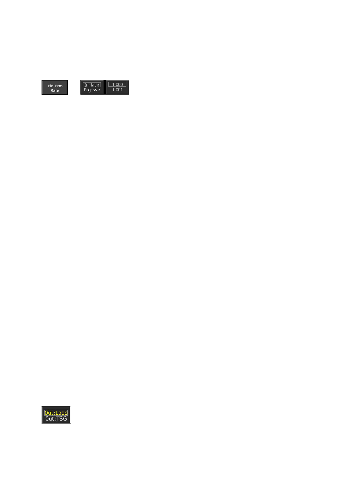
or 720 @ 1.5G, or SD @ 270MB), followed by the required Frame rate (24, 25, 30,
50 or 60Hz), and on 60Hz related standards, subsequent sub-selection between
1.000 & 1.001 rates. On non-progressive only standards, interlace may be selected.
Support for Level B Dual Link at 3G is provided.
Menu selection of the different Test signals is easy
and intuitive, with the Generator providing parallel SDI
and CVBS outputs of the selected Test Signal on SD.
Tri-level sync generation.
The CVBS video output can of course only be valid whilst the Test Chest is
generating at 'Standard Definition' on 525 or 625 Standards, and is muted on HD.
However on all high definition standards BNC 3 will output Tri-level syncs, and this
changeover is completely automatic and transparent.
Tri-level syncs may be looped from BNC 3 round to BNC 2, and then used as
an external reference for the Wave Form Monitor; this will particularly useful when
Test Chest is used to measure ‘Latency’ through digital equipment.
HDVI Signal generation.
Test Chest contains two HDVI ports using industry standard connectors
and suitable for use with commercially available, or pre-installed HDMI cables; one
each for input and output and both are independently available whilst the system is
powered. A digital DVI OP is available via a proprietary passive HDMI/DVI adapter.
These signals are primarily intended for use in Television based
Engineering applications, rather than ‘Multi-Media’ entertainment environments. So
although industry standard connectors are used for convenience, the generation and
display capability is pitched towards confirmation of function with SD and HD
Professional TV related display standards, and a non-exhaustive list of the generally
TV related Graphics standards that can be coherently displayed is tabulated in the
Specification section.
HDVI signals generated by Test Chest may be selected from either a
dedicated TSG or the LCD panel’s screen, and in either case the OP standard is
800x640. Either source may be used as a convenient HDVI stream for quickly
checking connectivity or system function, and neither are intended for detailed
system analysis purposes although elements of ‘681 are supported.
Unlike some other Generators producing a PC/Graphics output, the
signals produced by Test Chest’s separate Graphics TSG do not stray from ‘legal
values’.
If required, Test Chest can generate a separate SPDIF compatible audio
output too from the AES OP stream, via the Audio-POD’s integral BAL/UN matching
transformer.
Input looping ~ ‘Processing Amplifier’ mode.
SDI Equalisation and reclocking:
Using the Home Menu it is practical to “LOOP” external SDI signals
through the Unit and benefit from the internal equalisation and re-clocking
facility. Note that the menu flags this unusual setting with yellow text.
CVBS looping:
Test Chest will also loop CVBS inputs. CVBS will be ac coupled to remove any
Page 8
Test Chest: Manual
possible dc off–set on the input, and then clamped to remove dc changes due to
variations with Average Picture Level.
Text Ident:
A locally generated identification text string may be inserted into the
output video, a particularly useful feature when identifying long lines. The
Character Generator's non-volatile memory is pre-loaded with “TESTCHEST” when shipped; however it is very easily reprogrammed to individual
requirements by using the Text menu provided, an operation familiar to all mobile
phone Users.
External video Reference:
TC may be Gen-locked (Slaved) to an external video Reference, this
allows the output signal to be ‘timed’ to a Vision Mixer, for example.
The external reference is applied as either a Composite video, Composite
or Tri-Level sync to BNC2. Selection between modes is via menu icon. Be aware
that Mixed or Composite sync is only appropriate for SD, and that HD standards
require Tri-level syncs.
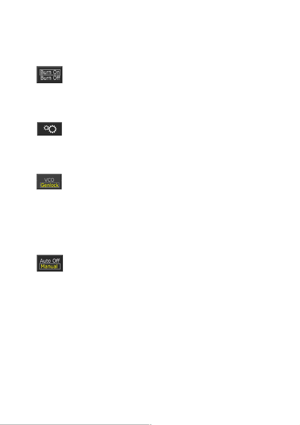
Genlock operation is initiated via the main menu's “Gear” icon, which
leads to the Set-Up sub-menu page. The TSG output will be maintained
locked within ½TV line of the Reference, enabling fully synchronous
operation with digital equipment employing 2H digital synchronisers.
Backlight:
Once the TSG mode has been set up, one may wish to reduce the LCD's
back light drive to a lower brightness. Using the 'Set Up' menu the brilliance may be
reduced, or switched to 'LCD DIM' mode to conserve battery power.
Auto/Manual Power Management:
Under certain circumstances it may be desired to set the Test Chest to
generate a test signal for a prolonged period, perhaps whilst tests are
performed elsewhere.
If no icon 'activation' is detected for 10 minutes, in ‘Auto off’ mode the Unit will
automatically shut down to conserve battery power.
This time-out may be defeated by selecting 'Always ON' in the main menu. Be
aware however that when running on battery power, the Unit will continue to operate
until the battery’s low voltage cut off logic activates. No Li-Po battery distress will
occur, but the Unit will not be capable of further battery powered operation until the
battery is recharged.
Murraypro recommend that the battery is recharged as soon as possible.
Test Chest may be used, and will continue to operate normally whilst it's
battery is being recharged. Charge completion is indicated by the extinguishing of
the yellow LED twixt BNC 3 & 4.
It is not necessary to remove the low voltage lead when charging is
completed, and Test Chest may be safely run for protracted periods with the
‘charge/external power’ lead connected.
Page 9
Test Chest: Manual
2b) Test Signal Generation~Audio
Test Chest generates audio in 3 different formats simultaneously:-
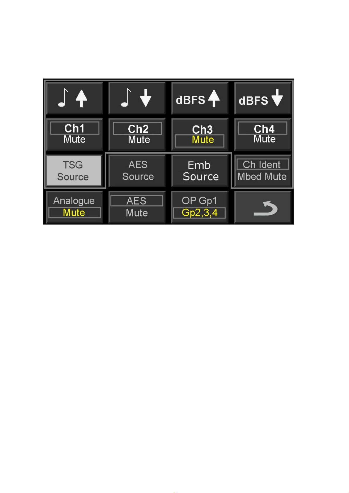
1) Embedded Audio is inserted in Group 1 by default, but Group 2, 3 or 4 may be
manually selected for instead. Each channel 1~4 within the selected Group
may be enabled or muted as required, with on-screen mapping to track and
display the current set up.
Audio modulation may be muted to ‘Digital Silence’. This does not affect the
digital house-keeping data, which is always generated.
2) AES output stream. This is enabled by default and runs in parallel with and
uses the same source as Embedded Audio, via the 'Generate Audio' page.
Channels 1 or 2 may be enabled, or muted as required.
The Unit’s dual channel AES output is presented on the D-25F
connector as an 110W balanced 48KHz AES encoded stream. This output
port is automatically coupled through to the Audio-POD when it is connected;
and it is accessed via the AES OP XLR3-M.
For Un-Balanced 75W AES operation, the balanced OP should be first
routed to the BAL/UN (110W:75W) transformer on the Audio-POD, and then
extended to the load from the POD's unbalanced AES 75 W BNC as usual.
3) Balanced dual channel analogue audio. Enable this mode which runs in
parallel with, and uses the same source as Embedded Audio, via the
'Generate Audio' page and, as with the Embedded Audio, Channels 1 or 2
may be enabled, or muted, as required.
The Unit's dual channel Analogue output is also presented on the D-
25F connector, and these low impedance balanced output ports are also
conveniently coupled through to the Audio-POD, where it is accessed via the
Analogue OP's dual XLR3-Ms.
Page 10
Test Chest: Manual
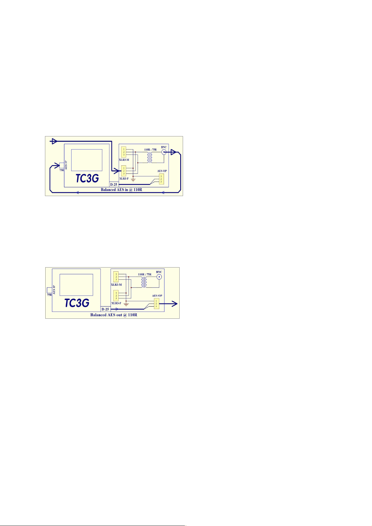
AES Matching with the Audio POD:
Generation & Monitoring
AES: Unbalanced IP @ 75 W.
Very easy, just couple the coax cable to BNC2 Test Chest’s main AES input.
AES: Balanced IN on XLR3-M @ 110W.
Couple IP cable XLR3-M to the POD’s
Transformer XLR3-F, and loop a short
BNC~BNC coax round to TC’s BNC2.
AES: Balanced OP @ 110RW.
Very easy! Just connect your XLR3-F cable to the POD’s AES OP.
AES: Unbalanced OP @ 75W.
Use an XLR~XLR ‘double ender’, couple
the POD’s XLR3-M AES OP back into
the POD’s transformer, and then plug
your coax cable into the POD’s 75W
BNC.
Output amplitude considerations:
The Embedded and AES digital audio bit-streams may be operated over a
much greater encoded amplitude range than that of the balanced analogue audio,
where practical considerations confines Test Chest’s limits to about +/-10dBU.
Do not confuse the encoded audio amplitude data with the actual amplitude of
the AES bit stream which remains unaltered, at around RS422 levels; normally
around 3~4 V PP.
Digital outputs may be adjusted in 1dB steps from 0dBFS down to -80dBFS.
This low output amplitude is useful for testing the digital microphone inputs of a
Mixer realistically. Whilst the overall envelope of the AES signal will remain at the
standard RS422 level at all times, digital microphones usually emulate their
analogue partners' low OP level, generating an AES output with a similar low digital
modulation amplitude.
Analogue amplitude:
The analogue audio channel is aligned such that a level of “-18dBFS” will
Page 11
Test Chest: Manual
produce a balanced analogue OP of 0.775VRMS = 0dBU, this is about 10dB below
the maximum OP. Users are reminded that the maximum balanced analogue output,
which does embrace the normal +8dBU peak programme level, is headroom-limited
by the internal battery voltage to about +10dBU.
Murraypro recommend using an external 60dB XLR/XLR attenuator if it is
desired to simulate 'Mic level' and similar low level analogue signals.
Audio Sources:
1) The internal audio oscillator offers menu selected spot frequencies, and
amplitudes.
2) An External AES input may be selected. Be aware that, although a 48KHz
source may easily be monitored and metered, it will not be practical to use it
as an Embedded source, unless the 48KHz input Word Clock is synchronous
with the output Video signal.
3) External Embedded Audio may be selected that has been extracted from the
signal applied to BNC1, the “Which-Wire?” input. Be aware that, as above,
unless the 48KHz input Word Clock is synchronous with the output Video
signal, it will not be possible to use it as an Embedded source.
4) TC3G offers a very powerful Utility in the “Audio Measurement” menu, which
indicates whether an external AES input signal is synchronous with a video
reference that is applied via the WW? Operation is described under the
following “AES/Video Lock Confirmation” passage.
5) A unique pulsed 'Tone PIP' identification can be added by TC3G to each
audio channel within a selected Group. This enables downstream monitoring
points to correctly, and unambiguously, identify each channel individually.
600
W
Audio loading:
Output loading: Test Chest follows current audio line driving practice, sending
from a current limited, balanced, low impedance source.
Test Chest follows Broadcast equipment’s input convention, by presenting a
balanced load with a high impedance comfortably in excess of 10KW.
600W loads are very unusual with current audio practice, and the significant
loading of the XLR3-M balanced output by a 600W termination will cause a reduction
in the output amplitude of perhaps a couple of dB, by potential divider action.
The outputs are current limited, and no damage will occur due to short circuits
or indeed 600W loading.
3) A&V Monitoring
TV Monitor:
TC3G incorporates a TV Monitor function with 800 x 480 pixel resolution
which automatically displays images in any supported Format.
Page 12
Test Chest: Manual
Mini-Histogram:
Tapping the lower left side of the TV monitor display will toggle the burntin Histogram ON/OFF. See later text for more information.
Aspect Ratio:
TC3G defaults to a 16:9 aspect ratio, but 4:3 images may be viewed in
their native format using the '16:9/4:3' menu option on the “Spanner”
Setup icon page for manual adjustment of Aspect Ratio.
This is Test Chest’s only non-automatic mode!
Measurement:
The TV Wave-Form Monitor and Vectorscope function accepts SDI & CVBS
sources, automatically switching as required. Video signals
from either may be displayed as either standard video signals
with H or V Timebases; or in H Parade mode, where the colour
information is sequentially switched between either the YRGB, RGB, YUV channels,
or in Vector format. To ease channel identification, the Parade display sequentially
adopts the colour of the signal being instantaneously presented.
WFM display may re-positioned on the LCD by simply touching the trace, and
dragging it to the desired position with a fingertip.
In the Composite video display mode, the WFM's HF response extends up to
well beyond 6MHz.
HDVI
Display:
Test Chest’s HDVI input port is designed to accept ‘TV display’ (SD~>3G)
formats adhering to ‘681, and whilst the port will accept signals on other graphics
standards, they may not be coherently displayed.
Use of industry-standard connectors enables PC Display, Graphic cabling,
and associated interfaces to be swiftly checked out. This useful feature should be
regarded as an additional integral facility, significantly expanding "Test Chest's"
existing capability, rather than as a substitute for a dedicated Graphics Test Set.
WFM & Vectorscope:
HDVI waveforms may be examined either on the Vectorscope or displayed as
a signal in WFM or Parade mode.
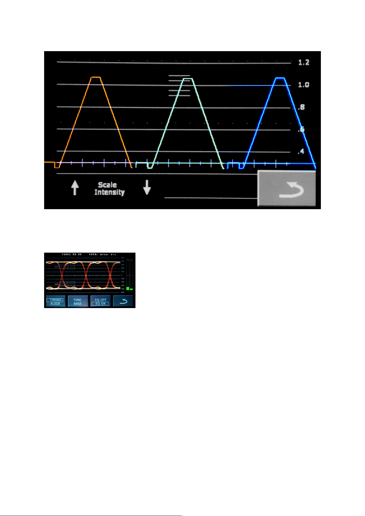
The Y channel display scaling adheres to Broadcast SMPTE standards, and
sources that do not conform with these are easily spotted. Excursions below black
level and above 100% are caused by coding with of out of range values, as the out
of gamut signal generated by this low cost HDMI generator demonstrates well!
Page 13
Test Chest: Manual
This HDVI input signal contains out of Gamut values!
Touch-Shift:
Using the LCD's touch panel, waveforms may be 'dragged' in both the X & Y
planes to align the trace with the graticule, to facilitate measurements.
The WFM display may, in SDI mode only, be
synchronised to an External Reference. This
Reference signal which may be either Tri-Level or
Colour Black, is applied via BNC2. BNC2 has a 75W
impedance and is also used for the dedicated AES
input and as the TDR port.
The WFM Vertical sweep display may be
expanded to reveal further detail during the active frame period.
Swiping fully across the whole width of the LCD screen in one continuous
action will increase both position in the Frame/Field, and the rate of shift. An onscreen counter displays the delay in 'TV Lines' between the WFM’s vertical trigger
point, and the start of the displayed period.
With PAL/NTSC CVBS sources, unlike the WFM, the Vectorscope displays
only 'Active Line Time' chrominance information, and the colour Burst is therefore
suppressed.
When confirming optimum White or Black ‘Balance’ on a Camera etc, the
display gain may be increased, using the icon on the Vectorscope menu page.
“EYE” and Jitter:
This feature is supported by the Test Chest’s EYE~POD accessory, which
provides the EYE and Jitter measurement capability, which is accessed via the WFM
Page 14
Test Chest: Manual
menu. Eye monitoring and making measurements do require this module, and are
not supported unless this is present.
Instructions for the use of EYE~POD are presented in the rear section of this
manual.
Audio Measurements:
The TC3G provides two independent type of audio level measurement,
“Histogram” and “Numeric”, and generally both forms are available simultaneously.
The histogram display is highly dynamic and primarily intended for use when
measuring programme audio amplitude, but is suitable for steady state tones too.
The numeric display, which appears on the top 'banner' field, is heavily
damped, and is only intended for use with steady-state tones.
Using the Test Chest’s 75W WW? input port, Audio Monitor mode provides
accurate audio level monitoring of embedded audio signals via the Audio menu.
Embedded audio levels for the selected Group are presented in histogram format, as
4 columns on the LCD screen, and it is immediately possible to unambiguously
differentiate between an AES reference level at -20FS and an EBU reference at 18FS, when using either measurement facility.
The histogram display offers menu selection between the quaisi-peak~semilogrithimic scaling of BBC PPM, Nordic, DIN & Digital scales or the more
transient VU Scaling + ballistics which offer additional sub-selection for operation
with different Reference levels.
The usual BBC PPM scale sensitivity (-18dBFS = PPM”4”) may be preset via
the audio menu so that either the ITU or SMPTE (-20dBFS) Operational Reference
levels are 'normalised' to read PPM = “4”, making the subsequent evaluation of
SMPTE programme audio level considerably easier.
The histogram's “Digital” scale has 1dB graticule gradations covering levels
from 0dBFS down to -29dBFS, with icon selection of additional switched gain blocks
of +30 and +60dB. This additional gain allows AES & Embedded level
measurements down to around -90dBFS.
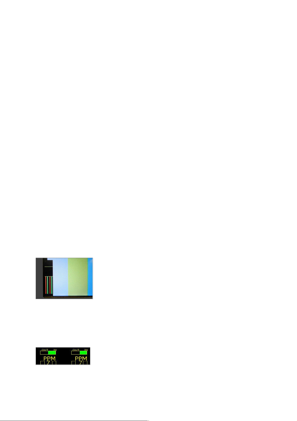
In-vision Histogram:
TC3G provides a neat in-vision histogram feature which may
be displayed whilst in the 'TV Monitor' mode. Useful for
confirmation that audio is being satisfactorily received,
especially when output from the loudspeakers is muted.
According to the type of the source, the histogram display may
be stereo or 4 channel.
This is a simplified display, bearing graticule points at -18 and
-10dBFS (=0dBU & +8dBU analogue) and emulates the full scale histogram scaling
selectable via the Audio Monitoring menu. The burnt in mini-display is enabled or
disabled by tapping the lower left region of the TV monitor's image where the
histogram would be/is presented.
Audio Phase:
Test Chest includes Audio Phase error detection for each of
the Ch1/Ch2 and Ch3/Ch4 pairs of the selected Group. With
embedded audio both channel pairs are presented; whilst with
balanced analogue input only the single stereo pair can be monitored. Either
detector will instantly "RED" flag a phase inversion of one channel, with respect to
Page 15
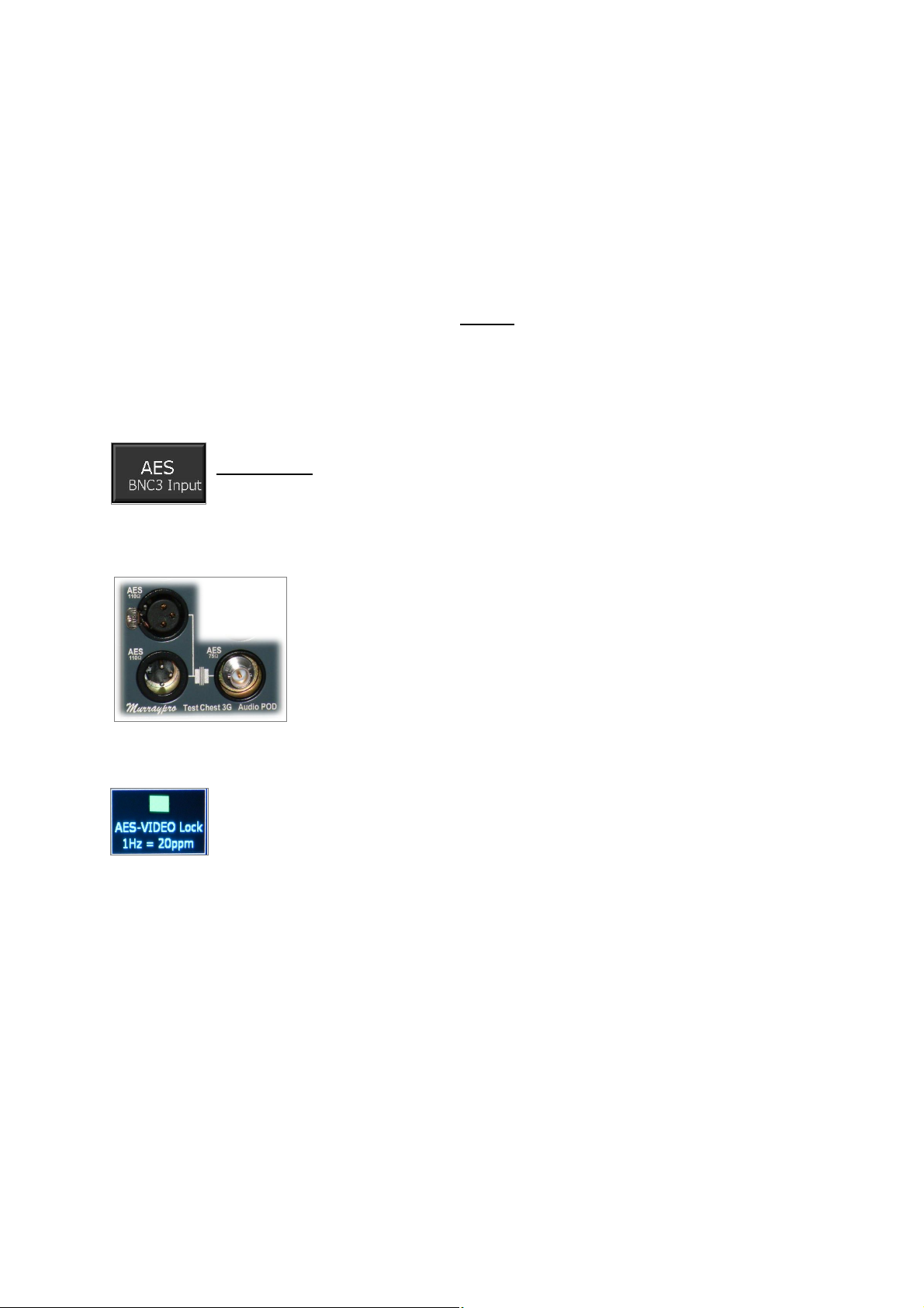
Test Chest: Manual
the other; and whilst the effect is instantly recognisable with steady state test tones,
it could take a moment or two before an error is apparent on Programme Audio due
to the varied nature of the real-world signals encountered. On a normal Programme,
with correctly phased stereo, one would anticipate only an occasional, and
momentary, "RED" flag; whilst in the presence of a phase inverted channel, one
might anticipate a near continuous "RED" flag.
TC3G digitally compares the amplitude of “M” & “S” channels derived from
each stereo pair. With true stereo (not necessarily true with ‘electronic’ music),
almost without exception the amplitude of the “S” channel will seldom exceed that of
the “M” channel, and then only on peaks, except in the presence of a phase error.
“S > M” will, after integration, therefore be flagged as an error.
Prolonged illumination of the red “PHASE” flag will leave little doubt that a
serious audio phasing problem exists, requiring immediate remedial action.
AES Audio:
Using the Selector on the Audio Monitor sub-menu, a 48KHz
unbalanced AES stream input on the 75 R BNC3, may be selected for
monitoring.
Essentially, the same options as for Embedded Audio are available.
Balanced AES IP:
Balanced AES sources should be first routed, to the BAL/UN
(110W:75W) transformer on the Audio-POD, and then
extended onwards, using a short BNC~BNC cable to BNC 2,
in the usual way.
AES/Video: Lock Confirmation
Test Chest includes a very useful Utility to confirm that the 48KHz
Word Clock of the AES input signal on BNC2, is synchronous with the
chosen Video Reference signal, fed in this case via BNC 1.
To use this feature, the AES INPUT mode should first be selected on
the 'Monitor Audio' sub-menu. The Reference Video, with which synchronism is
being checked, is applied to the 'Which-Wire?' input via BNC1.
When synchronous, the ‘lock’ flag should be a solid green. Should these
signals be asynchronous, the "AES LOCK" flag on the audio monitor page will
change state to red and will pulse at the 'beat' frequency, referring to their difference
at 48KHz.
Flash rate of 1Hz equates to a difference error of approximately 20 parts per million.
Audio Monitoring
Loudspeakers:
Be aware that when monitoring AES or Embedded sources, overall system
gain is controlled by the switched +30 and +60dB preset gain icons, with the
loudspeaker volume level being controlled with the up/down icons on the main menu.
Page 16

Test Chest: Manual
Using the Audio sub-menu the front panel loudspeaker may select between
‘Ch1 + Ch2’ or ‘Ch3 + Ch4’ pairs for each of the 4 audio groups. Stereo audio for
each channel pair 1&2 through to 15&16, may therefore be monitored on the
conveniently mounted front panel stereo speakers; or on Headphones when they are
jacked into the side-panel mounted 3.5mm socket.
When jacked, the headphones automatically mute the modestly dimensioned
loudspeakers, and furnish significantly enhanced audio quality.
***************** !!! CAUTION !!! *****************
Headphone operation
Users are cautioned to operate the Test Chest's headphone port with
restricted volume levels. Always advance the volume from an initial low setting.
The headphone output has limited current drive and is voltage limited by
design, but Murraypro has no control over User's choice of headphone.
Some high efficiency transducers, closely coupled to the ears, may be able to
produce pressure levels that are hazardous to hearing.
External Display
Sometimes it may prove useful to be able to port the Test Chest's 800x480
display on to an external PC type monitor. This is easily achieved using the 19 pin
HDVI output port at the top of the right side panel, active whenever Test Chest is
powered.
Low latency display
Test Chest’s image processing has been designed to provide acceptable
quality images on the internal 800 x 480 pixel LCD, and is a subtle balance between
conflicting ‘interpolation’, ‘latency’ and battery drain considerations. Our chosen
solution shuns power hungry interpolation techniques involving multi-frame storage
and digital multiplication, in favour of direct ratio-metric processing. This achieves an
impressive through-put with a maximum LCD latency of around 1 field (with
interlaced sources).
This is a neat solution for a battery powered Tester with a 5” panel, which
makes no attempt to offer “Grade 1” images. A major improvement in both
processing speed and power economy have resulted in excellent battery endurance
too, and ALL this has been traded for only a modest increase in interpolation
artefacts.
You may wish to ensure that the Power Management option on the main
menu is set to “Always ON” rather than 'Auto Off', or the Test Chest will
automatically de-power 10 minutes after your last key press!
Page 17

Test Chest: Manual
Additional functions are present within the Test Chest, and
these are discussed below:-
Audio Signal Tracer
The internal audio amplifier is also operational in WFM mode, and may be
selected via this three step operation:-
1) On the Home Menu, select the Input = “W-W?” option.
2) On the Home Menu, select the “Audio Monitor” option.
3) Tap the diagrammatic “switch” icon on the lower-left of the LCD screen until
“W-W? BNC” is declared at the end of the top banner text.
Note that although, normally Test Chest automatically pre-routes the
audio associated with the selected video source to the audio monitor;
the “switch” icon on the “Audio Monitor” page permits manual over-ride,
to give total flexibility. This might be particularly useful when comparing
an SDI embedded audio against it’s balanced analogue counterpart.
When the audio monitoring amplifier is switched to “W-W?” input (BNC 1),
this feature becomes a really useful tool for audio investigation and signal tracing.
Audio volume level is controlled by the Home Menu “up” and “down” selection.
Clapper Board
'Clapper Board' is a proprietary Test Signal that is designed to show Audio/Video
delay inequalities that a TV signal may have incurred, usually due to external Video
processing, and which has not been accompanied with the complementary audio
delay. It is not designed to correct an error, simply to demonstrate that one is
present, and which requires remedial action.
“Simplicity” is the word, and all that is required at a remote Monitoring Point is
a picture Monitor with low Latency, and a Loudspeaker.
The picture shows a diagrammatic, functional representation of the Clapper
Board signal as generated, for feeding to a Remote Location. The 'Puck' is
represented by the white dot which travels rhythmically across the screen from right
to left; and at 'time zero' a white flash is generated together with a brief pulse of
audio tone. The Clapper Bd's 'Puck' speed is calibrated so that each major graticule
division represents 100mS of time.
Page 18
Test Chest: Manual
Whilst 'Time zero', Flash and tone pulse are co-incident when generated;
subsequent (particularly) video processing incurred during progress along the Link,
may result in a delay in-equality experienced by the Audio and Video components.
An error of several Frames of differential delay is entirely possible, with a disastrous
effect on “Lip Sync”, an effect that will be painfully obvious to all downstream
Viewers.
At the Receive Point, the Observer simply judges precisely where the tone
blip actually occurs, with respect to the instantaneous position of the travelling 'Puck'.
It may help to estimate the error more accurately, if the screen zone outside the
area of interest is simply masked off temporarily with both the Listener's hands, to
leave a 'trackable slot' that is centred where the tone interruption occurs.
LCD Aspect Ratio
Users may wish to optimise the Aspect Ratio of the internal LCD panel in
order to display Heritage 4:3 pictures correctly.
The Test Chest’s LCD aspect ratio is toggled using the Aspect Ratio option
on the “Set Up” menu, accessed via the 'Spanner' icon. Note that this feature is only
operational when the LCD is displaying a TV Picture, thus ensuring that the menu
pages are always completely visible.
Cable Fault Detection (TDR)
Test Chest offers Time Domain Reflectrometry utility for the
identification, and location, of cable problems. The TDR launches a
fast pulse from a precision 75W source impedance, into the near end
of the problem network which is connected to the TDR port, BNC 2.
With a correctly terminated cable, all the launch energy will be absorbed by
the terminating load at the far end of the cable; however, should that load not
perfectly match the network’s 75W impedance, a percentage of the launch energy
will be reflected back from the far end of the cable, and is directly dependent upon
the magnitude of the error, very similar to a RADAR return. It is this reflected energy
which Test Chest detects and displays on the LCD’s display.
The TDR launches fast 16 nS pulses, and longer cables will have higher
losses, and so absorb more energy, thereby producing lower amplitude reflections.
You may wish to ponder the fact that with all cables, energy reflected from the far
end of any cable will have travelled twice that distance before being detected.
Users may choose to obtain improved performance and so resolve smaller
TDR artefacts by increasing the display gain, but the noise floor is compromised.
The X axis (Time-Base) of the display is calibrated in Metres for Belden 1694
(5~180M). An unterminated cable shows a positive reflection, whilst a short circuit
shows as a negative reflection, with distance to anomaly indicated on the X scale.
Page 19
Test Chest: Manual
The velocity ratio of this cable (0.82), is similar to that of other quality coaxial
cables, and the distances indicated may be used, with only a small nominal error, as
a direct guide with many other cables types.
In a 75W system Test Chest was very easily able to differentiate between a
correctly terminated system, and one which is:a) Open circuit (unterminated).
b) Incorrectly terminated in 110W.
c) Incorrectly terminated in 50W.
d) Double terminated with 2 separate 75W loads.
e) Correctly terminated, but containing an unterminated “stub”.
Tests demonstrate that a stub only 50mm long, T-Piece'd in, 10M before the
end of 110M of correctly terminated Belden 1694 is clearly detectable.
It is unlikely however that, unless significant, mechanical deformation due to
cable compression would be readily detectable.
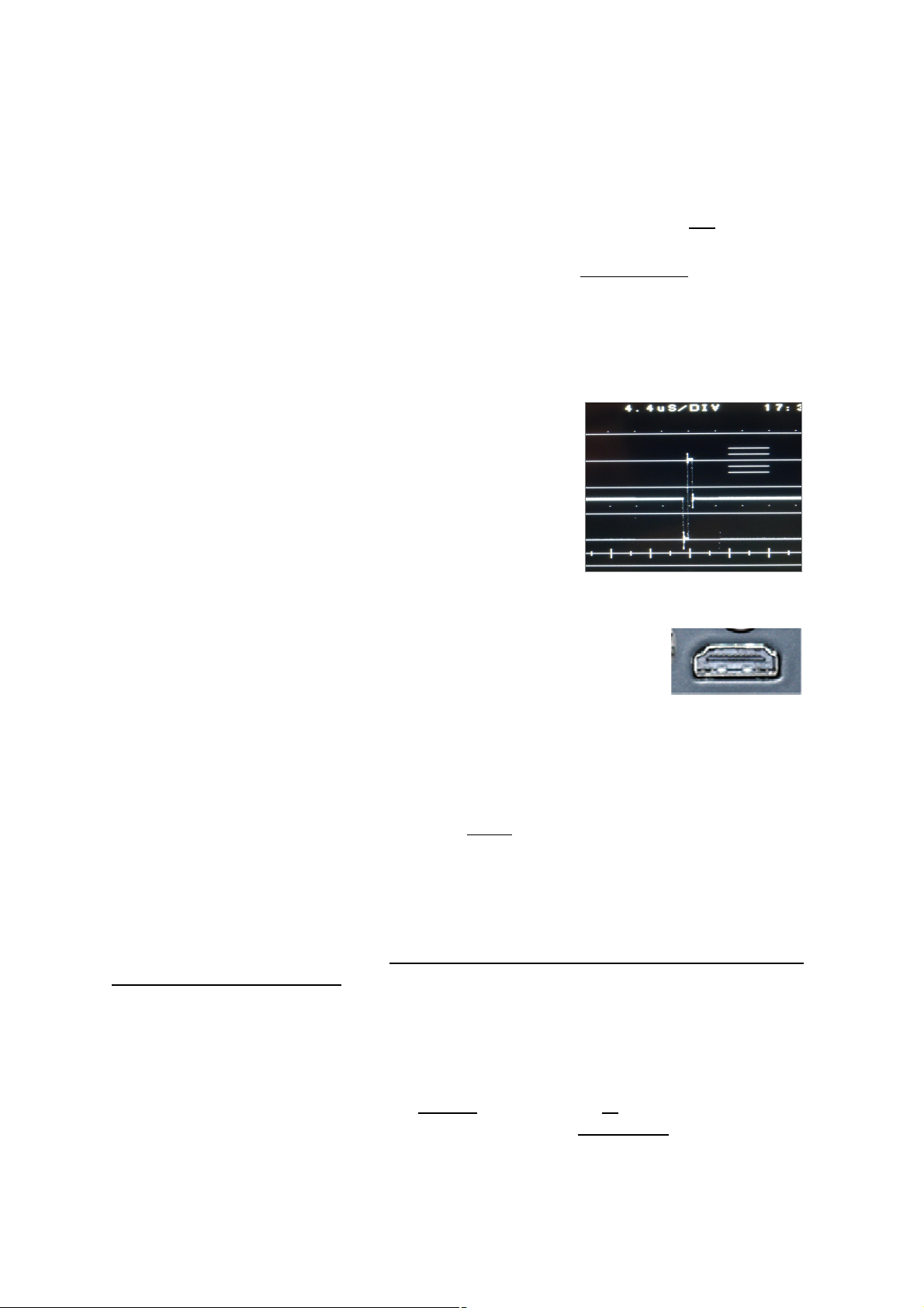
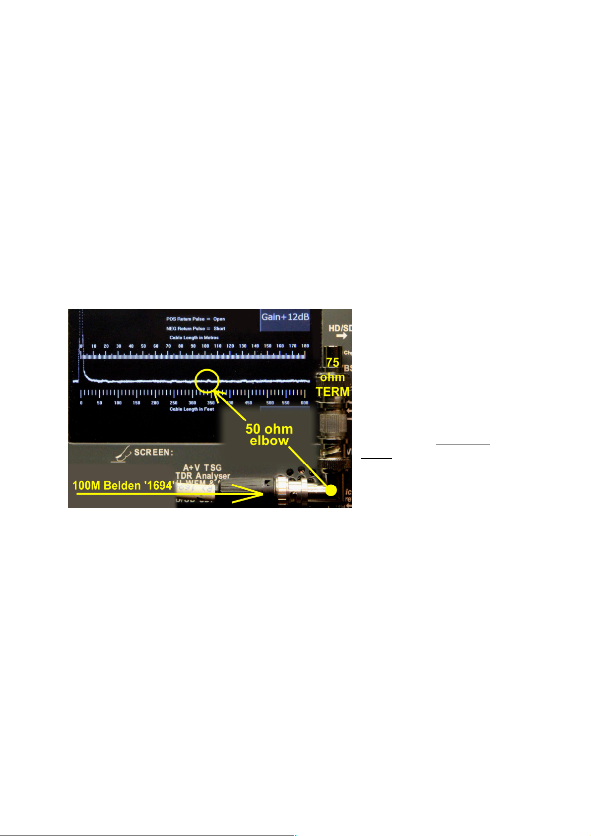
This annotated photo shows
Test Chest’s 16nS TDR
pulse probing a 100M high
quality coaxial cable and
revealing an obvious glitch.
This photo, taken following a
Client demonstration, shows
that this glitch is due to the
presence of a 50W BNC
elbow immediately before
precision 75W termination.
Remember, all this reflected
pulse energy has actually
traversed 200M of cable!
‘SDI Event’ logging
Test Chest incorporates an ‘HD/SD-SDI’ Error logging Utility which is
accessed from the main menu, through the ‘Set Up’ menu (Gear icon).
After initiation through the ‘Start Log’ icon, 8 parameters are continuously
monitored for error codes which, when detected, are logged against the internal
RTC. The Logger has been designed to operate independently of external time
references, and it is NOT necessary for the input video signal meta-stream to contain
VITC data, however an option to select VITC time for logging is envisaged.
A running count of the total number of errors that has been detected in each
of the 8 monitored ‘error’ fields is presented for information.
Logging:
Note that once initiated, the Error Logging continues in the background, even
if an operation on another menu page is selected.
Page 20
Test Chest: Manual
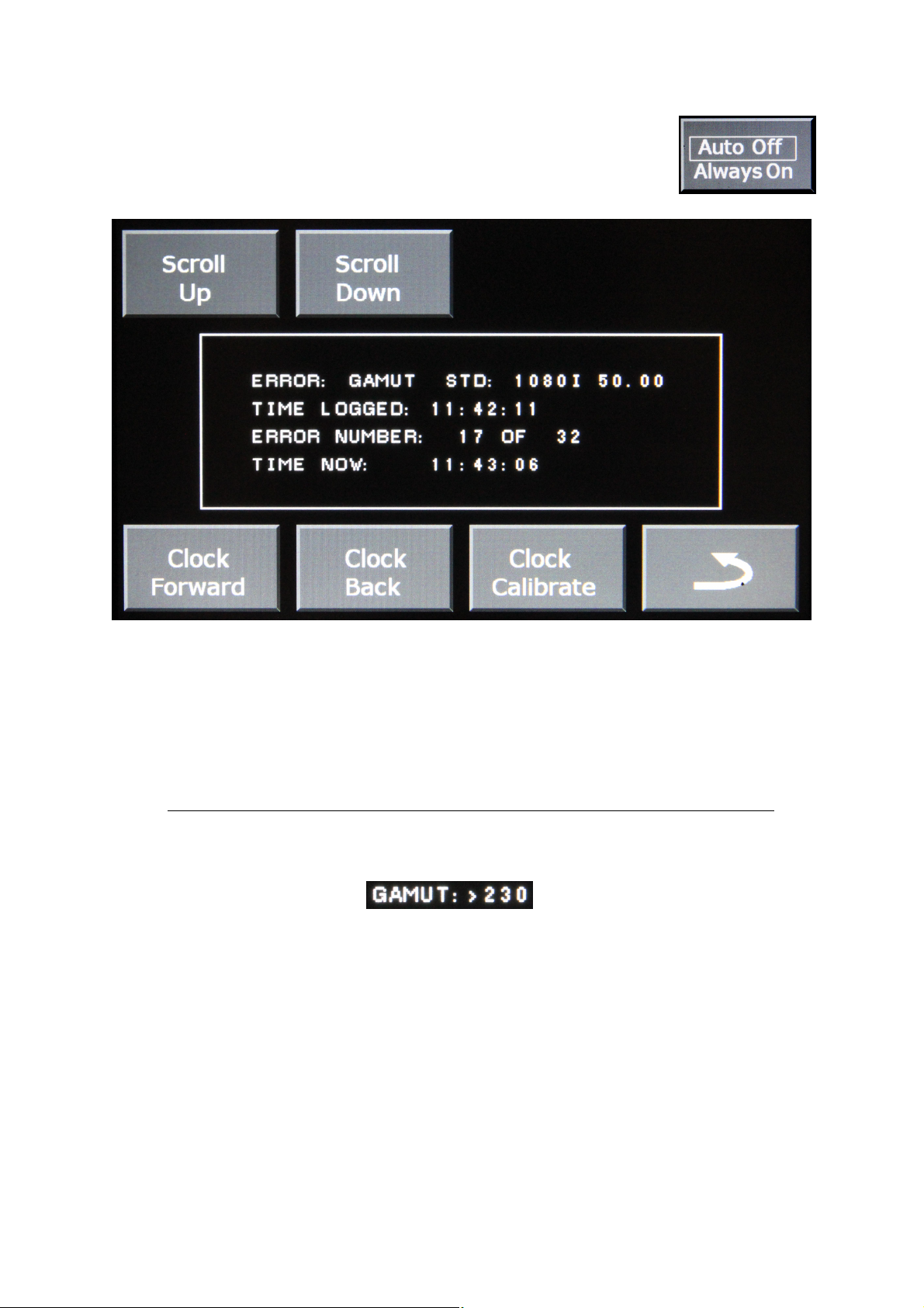
When Logging is in progress Test Chest forces the power
timer into “Always ON” mode. Else, with “Auto Off” mode enabled
powering down occurs 10 minutes after the last icon-touch, and
this might just prove to be very annoying!
The ‘Auto Off’ default power setting is automatically re-instated when the
logging activity terminates.
Operation under battery power is time limited, and the internal battery’s
endurance will be determined by age, condition, state of charge, and the Clock
speed of input signal being monitored. Nominal figures for guidance below: SD-SDI HD-SDI 3G-SDI
Battery current 720mA 800mA 900mA
Nominal endurance 4H 3.75H 3.3H
Mains powered operation is recommended for lengthy logging operations!
The non-volatile memory stores the first 100 logged events, with up to 230
occurrences of each type counted, and when present indication of counter overflow.
Error flags are generated when any of the conditions below occur:-
1 Timing Reference Signals: SAV & EAV protocol error detected.
2 Ancillary Data (various): CRC invalid
3a CRC-AP: Check Sum failure for the SD only ‘Active Picture’ area.
3b CRC-Y: Luminance Check Sum error HD only.
4a CRC-FF: Check sum failure for the SD only ‘Full Frame’ period
4b CRC-C: Chrominance Check sum failure HD only.
5 Line: Declares that ‘encoded line number’ declared in HANC is incorrect.
6 Lock: Confirms SDI receiver ‘unlocked’ in the presence of valid SDI source.
7 Illegal: Confirmation that value ‘000’ or ‘FFF’ has been detected.
8 Gamut: Y/C Colour Space LPF’d values exceed -1% or +103% system limit.
Page 21
Test Chest: Manual
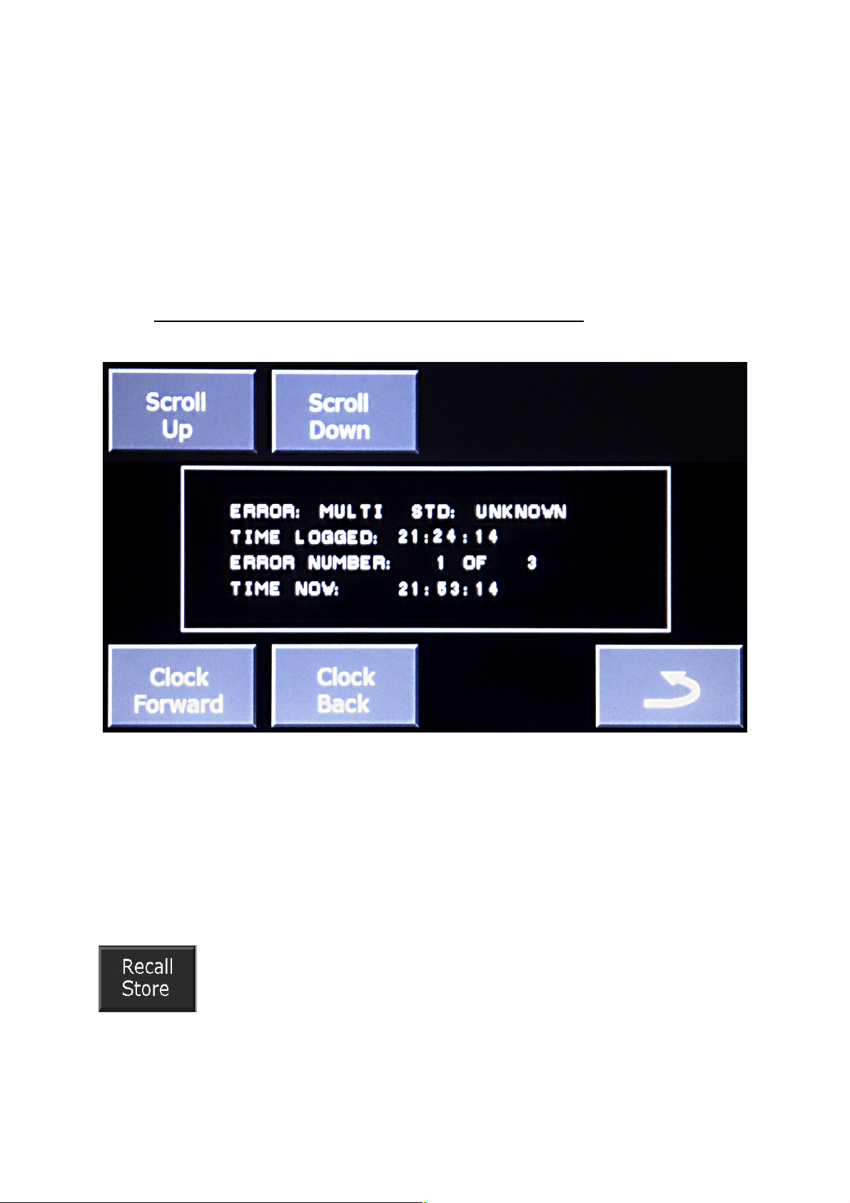
Read Log:
Selecting the Read Log icon immediately stops the current Logging operation
and switches to the Stored events page, where intuitive icons speed Users to the
stored Event of interest.
The first 100 events are stored in the memory, thereafter writing ceases.
However the 8 respective Event counters will continue to increment independently
up to 230, when over range is indicated.
The internal memory is accessible via the USB Port, and the stored event Log
will be downloadable to a PC for subsequent investigation, using a software Suite
that is currently in development.
Reselecting “START LOG” will flush the storage memory and the Event
counters, which recommence from zero.
VITC Reader
Test Chest contains a Reader which decodes VITC (SDI only) on BNC1 and
displays the decoded time, preceded with a “V”, in the banner on the LCD.
Configuration Memory
Test Chest contains memory which stores 10 User-configurations.
These are held in non-volatile ROM, and may be recalled to over-ride
the default 'Last used' configuration which is automatically loaded at
manually initiated power-up. Write/Read operations here are intuitive
too, and further instructions are not given.
Page 22
Test Chest: Manual
Reset
From time to time occasions may arise where a User might wish to
“soft” reset all Test Chest variable options to their “nominal” settings.
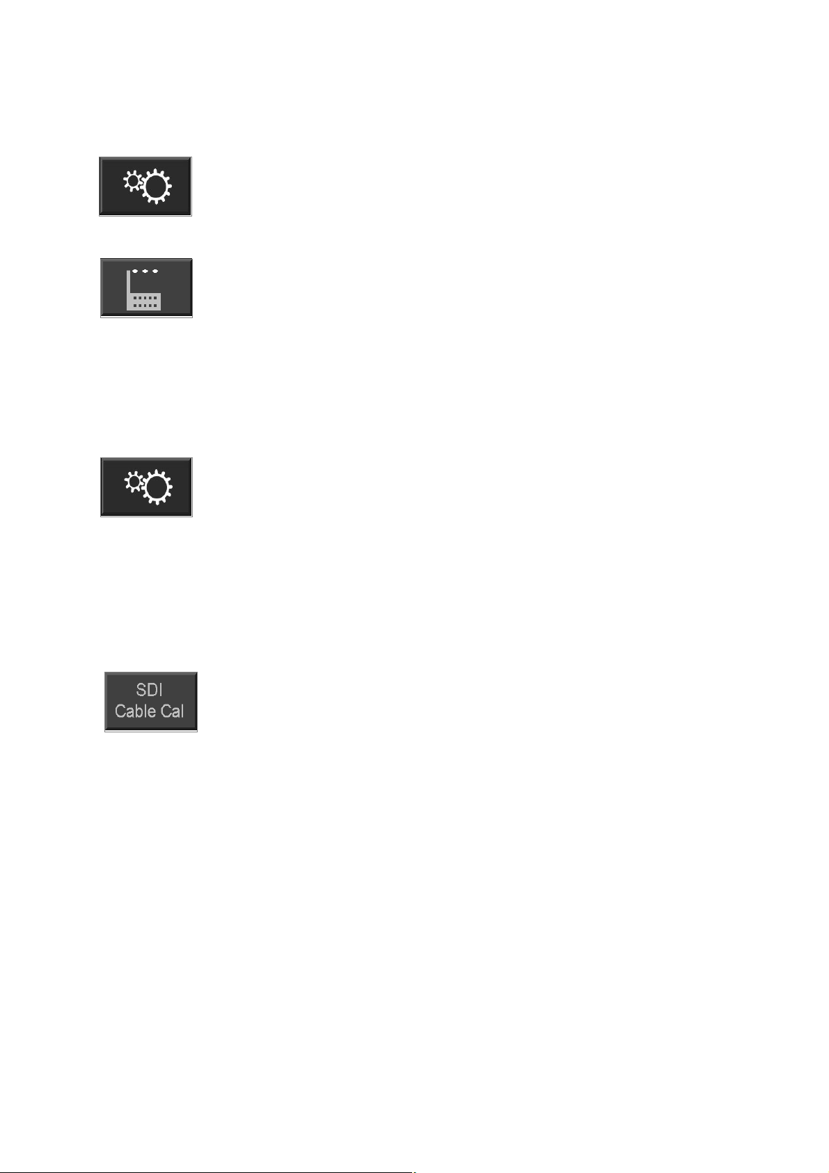
This option is selected via the 'Set Up” icon on the Home Menu.
***************************CAUTION******************************
Be aware that this immediately pre-loads default median values, but
‘Master Oscillator frequency’, ‘Analogue audio ADC off-set’, and ‘SDI
Calibrate’ parameters will be reloaded with individual values
established during their factory alignment
We have supplied the alignment instructions later in this manual to optimise
Master Oscillator frequency, and the ADC off-set, if these are required.
SDI Calibrate
A really useful utility is Test Chest’s cable comparator which
provides the ability to quickly compare different cable lengths.
After selection of cable type, length and TV clock frequency, a
composite performance parameter is stored for your chosen ‘reference’
cable via the 'Set Up” (Gear) icon (SDI Cal). The performance of any
cable subsequently plugged to BNC 1 is compared against this stored reference, and
a declaration as to whether more or less SDI equalisation is required to ‘normalize’
the cable in use is instantly presented on the LCD’s banner.
By way of example, we will choose 100M of Belden 1694A cable and 1.5GHz
Clock (1080i 50Hz) as our “Reference”, and then store this loss value.
Having defined our Reference’s parameters, take one end of your
Reference cable to the Test Chest SDI output on BNC4, and loop the
far end of the cable round to BNC1. Store this value by tapping the
“Set SDI Cable loss” icon in the Set-up menu.
The SDI Cal’s “Reference” value may be reset for a different
cable Type/Length/Clock at any time, simply by initiating the ‘SDI CAL’ command.
The losses associated with a longer length of cable (for the same system-
clock & cable type) will clearly be higher with longer cables, and lower with shorter
cables. The difference between previously stored “Reference” loss variable, and loss
associated with the current input signal, will be declared on the banner at the top of
the LCD panel as ‘Hi loss’ = Longer than Reference; or ‘Lo loss’ = Shorter than Ref.
Nota Bene:
Note that “Hi loss” does NOT necessarily infer that your current cable is faulty,
only that it is requiring more SDI equalisation than your reference cable!
Pressing the Factory RESET icon in the set-up menu will automatically
restore the Reference value for 100M of Belden 1694A cable @ 1.5GHz.
Choosing a ‘longish’ length of cable (as above) for your reference can be
useful (especially at 3GHz!), as it can offer timely warning that the ‘Digital Cliff’ could
be approaching, something much less likely with significantly shorter cables.
Page 23

Test Chest: Manual
Battery, Switch & Charger
Li-Po battery pack, and charging
Test Chest uses an internal battery comprising 2x Lithium Polymer cells
connected in series. When fully charged, Users may anticipate a minimum of 2 hours
endurance. By reducing the LCD backlight drive, a function on the main menu, a
useful extension in battery powered operation is achievable.
Be aware that generally logic devices’ power consumption increase with
system clock speed, and that HD operation at 3GHz clock frequencies can consume
25% more power than SD operation at 270MB. This has a measurable influence on
endurance when on operating under battery power.
Battery packs are fitted with connectors but are not operationally ‘swappable’.
They are however considered ‘field replaceable’, so please contact Murraypro for
information concerning the supply of replacement battery packs.
The battery pack is charged automatically as soon as low voltage external
power is applied, via the 2 pin Lemo connector. An intelligent charger monitors the
cells' voltage, charge current and temperature throughout the charge cycle, thereby
ensuring that the battery recharges as quickly as practical, consistent with the
Manufacturer’s specification.
The internal battery charger monitors a number of parameters, as above, and
will prevent overcharge, no matter how long the external power is connected.
From “flat”, expect the Test Chest battery to be fully recharged in 2~3 hours.
Note that manufacturers suggest that the performance of a new pack will improve
after a few charge/discharge 'conditioning' cycles.
The “Battery Charging” status is flagged by the illumination of the yellow LED
between BNC 3 & 4. The LED extinguishes when the charge process is complete.
The battery is protected against “deep discharge” damage by a special low
voltage detector which powers down the Test Chest when the cells have discharged
to their minimum safe level. Prior to that time the battery voltage histogram at the
top of the LCD panel will give warning that only a limited period remains before
automatically shutting down.
The 3V6 Lithium Polymer cells fitted in the battery have a capacity of
3000mAH, and are anticipated to have a service life in excess of 500
charge/discharge cycles.
Murraypro supply a +12V regulated supply that is capable of operating Test
Chest whilst it recharges the battery. An external power source between +12V and
+15V dc, and capable of sourcing of 1.25A via the 2 pin Lemo connector, should be
suitable. The 'red dot' on the connector, adjacent to pin 1, identifies the +Ve input.
During the charge cycle, it is usual for the cells to become gently warm, and a
rise of 10 - 15oC is entirely normal. The internal monitoring of cell parameters
provides a high measure of protection against overcharge.
Standby mode
Users will be aware that with all re-chargeable batteries there is a degree of
“self-discharge” (virtually negligible in the case of Li-Po), and there is also a tiny
“Which-Wire?” quiescent current drain too which reduces the level of stored charge
with time. This drain is small, and even after 6 months ‘standby’ well over 50% of the
charge should remain.
Page 24
Test Chest: Manual
If Test Chest has been stored for several months Murraypro recommend that
the battery is given a “topping up” charge before use.
Battery “off” switch
Test Chest is fitted with a ‘battery disable’ switch which is mounted on the left
end panel adjacent to the D-25 connector.
This switch is usually in the “Norm” position, and the Unit will then be ready
for instant service.
If storage is envisaged for any significant period, or the screen may be
‘touched’ whilst in short term storage, then it is recommended that the switch is set to
the “BATT Off” position. This disables most of the internal load, but power to the
Logger’s Real Time Clock will be maintained.
Software Version installed.
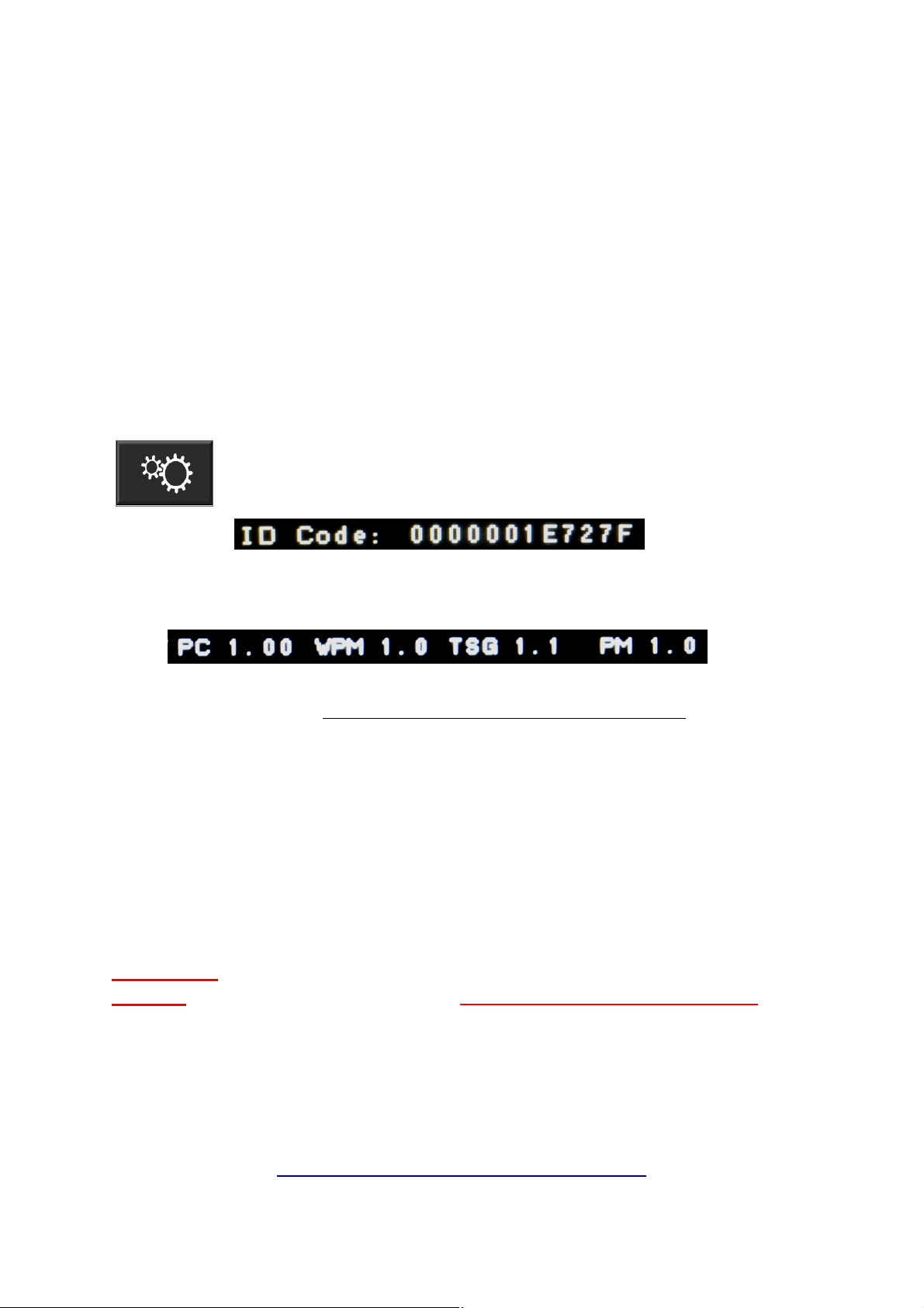
Test Chest contains four re-programmable devices, ‘PC’, ‘WPM’,
‘TSG’ & ‘PM’.
First select the ‘Setup Menu’, and the unique ID Code of the main
PCB is reported at the top of this screen.
Select ‘About’, then the installed software suite for each device will be reported at the
top of the screen.
Information regarding the latest software revision available is reported on the
Test Chest web site at:- http://www.murraypro.com/testchest.htm
Flashlight
By activating the press switch on the left end panel, TC3G provides a beam of
white LED light, from the lens on the right panel to illuminate those dark and
inaccessible areas which seem to be liberally positioned throughout the Broadcast
TV environment. Cable colours and numbers are brilliantly illuminated in an instant,
removing ambiguity caused by poor lighting.
CAUTION! The high efficiency White LED in the flashlight is extremely bright.
NEVER stare directly into the light, or DAMAGE to EYES could occur.
Frequently Asked Questions
Sometimes a different 'angle' may help resolve an issue, and we have a number of
FAQ presented for perusal at:-
http://www.murraypro.com/testchest_faq.htm
Page 25

Test Chest: Manual
Although great care has been taken to ensure that the information given in our
documentation is as accurate as possible, errors can occur......
Should you identify, what you believe to be an error, or perhaps a Test Chest
operation that you feel requires revision, or a new instruction, please email your
suggestion to us at:-
E: tech@murraypro.com .......and we thank you for your interest
Test Chest: Specification
The Specification of the Test Chest is subject to a process of continuous review and
development, and will be subject to revision. Hardware upgrades require return to
the Works for installation, and will be announced from time to time. Information
relating to the latest Software Suite is given on the Murraypro Web Site:-
http://www.murraypro.com
INPUTs: BNC1: “WW?” 75W 1% terminating.
BNC2: External sync IP.
BNC2: AES& SPDIF @ 75W.
HDVI: 19 pin PC graphics IP port
OUTPUTs: BNC2: TDR port.
BNC3: CVBS (SD Only), 1 Volt into 75W load.
Tri-Level (HD only) 600mV into 75W load.
BNC4: SDI, 800 mV into load of 75W..
HDVI: 19 pin PC @ 800x480 graphics OP port
Headphone: Stereo 3.5mm Jack, 30W.
Which-Wire?
Power on; Auto-power up upon signal detection.
Sources: Automatic 3G/1.5G/270M-SDI & CVBS ~ displayed in TV mode,
Composite/Tri-level sync ~ displayed in WFM mode,
AES/SPDIF digital audio ~ Histogram display + de-embed speakers,
HDVI ~ graphics display mode,
Standards: Auto-detection of IP.
Aspect: Setup selectable to 16:9 (default) or 4:3 aspect ratio.
Legend: On-screen text field declaring detected Video+Standard.
Test Signal Generator
Test Signals: 100%, 75% & SMPTE Colour Bars, White field, Red Field, Black Field,
2T Augmented Pulse & Bar, Multiburst, Grill, PLUGE, Bow-Tie.
5 Step Staircase+Chroma, Sawtooth & Chroma, Pathological Test.
Luminance ON/OFF
Chroma ON/OFF
Puck ON/OFF
Circle 16:9/4:3/OFF
Clapper Bd ON/Normal
IDENT User programmable burnt-in character: ON/OFF.
Page 26

Test Chest: Manual
SDI Generated with 10 Bit precision.
CVBS Generated to with 8 Bit equivalent precision, 0.5'DP & 0.5%DG..
A+V Sync Clapper Board, proprietary Test Signal.
Video Generate & Monitor
1080p @ 50, 59.94, 60Hz. Level A (3G)
1080p @ 50, 59.94, 60Hz. Level B (3G)
1080ps @ 23.98, 24, 25, 29.97, 30Hz (1.5G)
1080i @ 23.98, 24, 25, 29.97, 30, 50, 59.94, 60 Hz (1.5G)
720p @ 50, 59.94, 60Hz (1.5G)
625i @ 50 Hz PAL + SD-SDI (270M)
525i @59.94 Hz NTSC + SD-SDI (270M)
HDVI TX @ 800x600
HDVI RX @ TV related scan standards.
Genlock: External IP on 75W BNC2.
CVBS Video, Composite sync, Tristate video.
Lock tolerance <0.5 TV line
Internal Audio Generation
Osc: 125, 250, 500Hz, 1K, 2K, 4K, 8KHz;
Amplitude: 0dBFS ~ -79dBFS in 1dB steps
Analogue OP: Dual, balanced low impedance drive, limits +/-10dBU nominal.
Embedding: Ch1, 2, 3, 4 Individually mutable, routed to Group 1, 2, 3 or 4.
Channel Ident: Ch1 ~ 4 of selected Group have unique Tone-Pip identification.
All Ch Ident: Each of 16 channels identified sequentially
AES: 110W ac coupled, balanced line.
OP Mute: Independent for Embedded, AES and Analogue channels
Waveform Monitor
Input Video: Uses “WW?” 75 W input, BNC1.
Video level measurement with SDI source + 0.1dB
Video level measurement with CVBS source + 0.3dB
HDVI; Uses HDVI IP port
TimeBase: 2H, H, H mag, 2V, V, V mag (with line count of trigger/display delay)
Shift: X shift, Y shift.
Parade: YRGB, RGB, YPrPb, available on SDI & CVBS inputs.
Traces appropriately coloured for identification.
Response: Analogue WFM: 25Hz-6MHz, +0.5dB, -3dB @ 10MHz.
HDVI
Input: Non-exhaustive list of coherent images include~
480i@60Hz H:720420p@60HzH:720
720p@60HzH:1280720p@50HzH:1280
1080i@60HzH:19201080p@60HzH:1920
576i@50HzH:720576p@50HzH:720
1080i@50HzH:19201080p@50HzH:1920
1080p@24HzH:1920720p@50HzH:1280 3D TB
Page 27

Test Chest: Manual
1080p@24HzH:1920 3D SH1080p@24HzH:1920 3D TB
720p@60HzH:1280 3D SH720p@60HzH:1280 3D FP
720p@50HzH:1280 3D SH720p@50HzH:1280 3D TB
(SH = Side/Side HalfTB = Top & BottomFP = Frame Packing)
HDCP# EDID# or CEC# are not specifically supported..
Output: Either ‘LCD-Panel’ display, or HDVI TSGen.
Cable Fault
Range: 0-180M TDR Cable fault indicator @ 75W iterative impedance
Pulse: 16nS & 32nS width.
Detects: Open circuit, High impedance, Correct, Low impedance, Short circuit.
Audio Measurement
IP signal: De-embed Group *1, 2, 3, 4 from the SDI input signal.
Unbalanced AES: 48/96/192KHz, on 75W BNC3.
Balanced Analogue, stereo.
Group: Menu selectable *1, 2, 3, 4
Pairs: *A1&A2, through A15&A16.
Level Meter Histogram: PPM (BBC/Nordic/Digital) or VU ballistics & scaling.
Numeric readout: ‘Slugged’ ballistics with dB resolution for ‘Tone’.
Analogue: -10dBU ~ +10dBU range, nominal.
-1dB @ 30Hz & 20KHz
-3dB @ 12Hz & 30KHz
Digital: -90dBFS ~ 0dBFS
AES/Video 48KHz Lock confirmation GREEN: 20ppm error = 1Hz Flagged RED.
Audio Phase Detection of “S = +3dB>M” error, flagged Red.
AES Utility: 110<~>75W Bal/Un-Bal bi-directional conversion via Audio-POD.
(* = default pre-loads. All measurement tolerances are nominal, typical values.)
Audio Monitoring
IP selection: De-embedded, AES, Bal Analogue, BNC IP
'Speakers: Internal stereo speakers mounted on the front panel.
2x 80mW drive. <250Hz - 5KHz response.
'Phones: Jacking in mutes internal speakers.
Current limited drive to 30W transducers.
30Hz ~ 20KHz, -1dB
Character Generator
Generator: 15 ASCII characters per line
Storage: Non-volatile RAM.
Configuration Memory
Store & Recall 10 User set configurations.
VITC
When present, VITC is read and displayed on TV Monitor's banner.
Page 28

Test Chest: Manual
Electrical
Battery: Internal, pluggable, customised 3000mAH Lithium Polymer battery
Endurance: >3+ Hours Test Chest only @ 3G.
DC Input 2 pin male, mates with:- Lemo: HGG-0B-302-CLRP (Red dot = +Ve)
PSU: External 15W 3 pin IEC-320 mains PSU, permits battery charging &
simultaneous (non-time limited) mains operation.
Charging: 3 Hour nom from flat. Ext 12V @ 1.25A.
Float charge: Automatic cut-off, Unit may be left connected continuously.
External dc: 12V-16V dc external power for full function.
LVC: Automatic “deep discharge” low voltage cut off.
LCD: 5””, 800 x 480 pixel, 110 x 65mm, 16:9 Aspect ratio,
Touch screen command entry, NO keyboard or 'Hot Keys'.
300mCD/M2, Contrast: 450, Viewing: X 140’, Y 130’.
FlashLight: High efficiency white LED. Caution: Do NOT flash into eyes.
Physical
Robust alloy case.
Test Chest Unit: 1KG nom
Size: X:180mm, Y:140mm, Z:35mm nom.
Test Chest + Audio-POD 1.5KG nom
Size: X:280mm, Y:140mm, Z:35mm nom.
Test Chest Unit + POD & PSU in Carry case 2KG nom.
Size: X:290mm, Y:250mm, Z:95mm nom.
Current Firmware
PC:1V0 WPM:1V0 TSG1V1 PM: 1V0 Nov 2015
Reported at:- http://www.murraypro.com/testchest.htm
~~~~~~~~~~~~~~~~~~
EYE~POD
‘POD’ accessory to display ‘EYE’ & ‘Jitter’ characteristics.
False colour Eye display for clarity.
SD, 1G5-HD and 3G-HD
View 'RAW' or 'Equalised' stream.
WFM display 3, 10 & 30 Eye
Dual (but separate) histograms for Alignment & Timing Jitter modes.
Equalised & Reclocked Utility SDI throughput, for external equipment.
Controlled via Test Chest 800 x 480 Px Touch Panel.
Couples to TC3G via D-25 connector.
Size: 75 x 140 x 35mm nom.
(Provisional Spec)
Page 29
Test Chest: Manual
Alignment:
Test Chest is supplied pre-aligned and fully tested. Under normal
circumstances the adjustments below are not required, however following any
unauthorised "Tweeking", including an unintentional ‘Factory Reset’ command, the
following procedures may be invoked to correct off-sets that may have been
unintentionally introduced.
Audio ADC offset:
This may be required if the analogue histogram display shows residual
low amplitude noise with no Balanced input present.
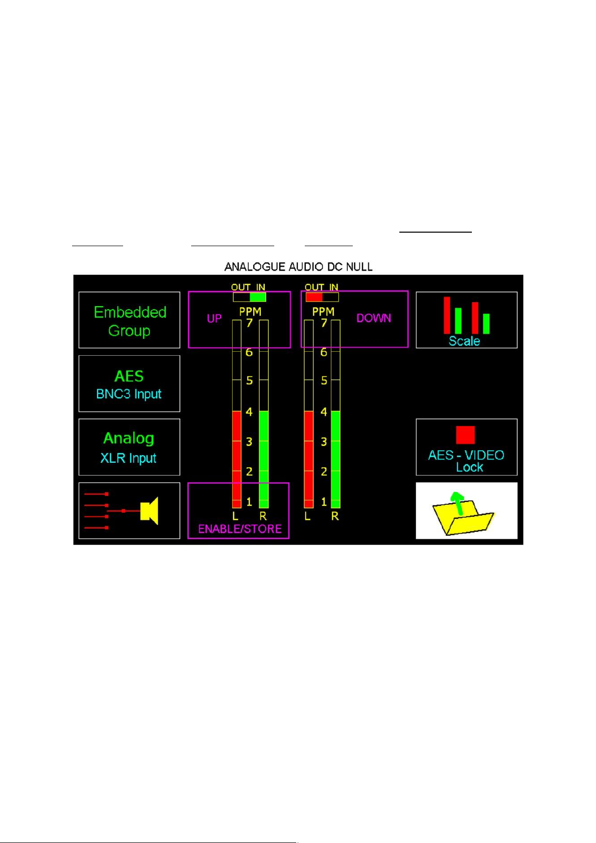
Be aware that the “Mauve Icons” shown below are NOT actually
displayed, it only their relative position, and functions, that are important here:-
1) Select “Analogue XLR IP” on the Audio Measurement page. Ensure the AudioPod is not connected, and select “VU” mode on the audio histogram, and that the
histogram is displaying low level pseudo-noise.
2) Briefly touch the LCD in the boxed area indicated as "Enable/Store" to initialise
the setup menu. A numeric count, indicating the ADC's offset value will be presented
at the top of the screen.
3) Briefly tap the position of the "UP" box and observe whether the displayed
histogram 'noise' increases, or decreases.
4) Continue to tap the "UP" or "DOWN" box until the error is just removed. Note this
on-screen ADC offset reading.
5) Continue to tap the same box, until the histogram error re-appears. Note this onscreen ADC reading too and subtract the smaller value from the larger value. A
difference of 8 to 10 is typical.
6) Divide this value by two (to produce a value of perhaps 4 or 5), and tap the
"DOWN" or "UP" box as appropriate, to centre the offset. STORE this value with a
single tap of “Enable/Store” which enters this value, and clears the setup mode.
Page 30
Test Chest: Manual
Master 27MHz: Accuracy
All the Test Chest’s generated outputs are referred to the internal 27MHz
oscillator, (unless it is gen-locked to an external Reference IP) so it is important that
its own frequency is as accurate as possible.
Broadcast SPGs for PAL use usually have highly accurate
oven controlled high stability reference oscillators which are capable of
maintaining an accuracy in the region of + 1 Hz @ 4433618 .75Hz.
Professional SPGs used entirely with digital Systems generate pulses
that should have a similar level of accuracy. A Composite sync, or
‘Colour Black’ OP of this SPG (see below) are normally easily
obtainable.
GPS timing is significantly more precise, as that system is directly locked
to Atomic Clocks. However, their 1Hz OP, whilst likely to be more accurate, may be
less convenient to use.
If using a GPS 1 Hz reference, it will be found beneficial to trigger the oscilloscope's
timebase using the "Triggered" mode, rather than the "Auto" mode. A digital
oscilloscope is recommended for use with GPS references, as the 1 Hz refresh rate
will result in a very dim trace when using an analogue 'scope (see below).
27MHz Oscillator adjust.
This oscillator is adjusted using the "Setup" menu (Gear Icon), selected from the
Home page.
1) Set Test Chest to generate a standard definition 625 100% Colour Bar. This is
important as TC mutes the Composite Video output when generating HD signals.
2) Prior to any adjustment you must have access to Composite sync generated by
an SPG of high stability, or a GPS receiver which produces a 1 Hz pulse output.
3) Either of these References may be used to externally trigger an oscilloscope
displaying the CVBS output from TC's BNC 4.
4) Adjust the oscilloscope’s timebase so that a 2H display of SD 625 Colour Bar
waveform is presented. At this stage the display will be asynchronous, and so drift
slowly across the screen.
5) Tap "VCO UP" or "VCO DOWN" icons as appropriate to reduce the speed of
horizontal drift to the minimum practical.
6) When satisfied, tap the "SET VCO" icon to store this setting.
EYE~POD
This section of the Manual is equally applicable to our earlier “Test Chest 3G”,
although this text will only refer to the current “Test Chest” model.
EYE~POD is available as an accessory for use with Test Chest, and is not
supplied as part of the basic unit. Current TC units are supplied fitted with the
hardware interface and software required for EYE~POD operation, but any preexisting TC3G Unit may be upgraded for EYE~POD operation by Murraypro at
Page 31
Test Chest: Manual
modest cost. There is no question of ‘existing inventory obsolescence’ when using
TC3G with the EYE~POD module.
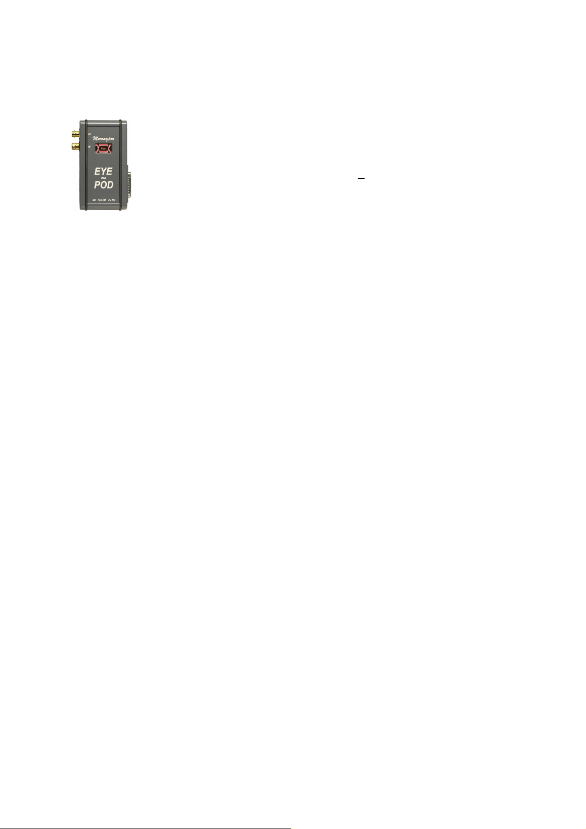
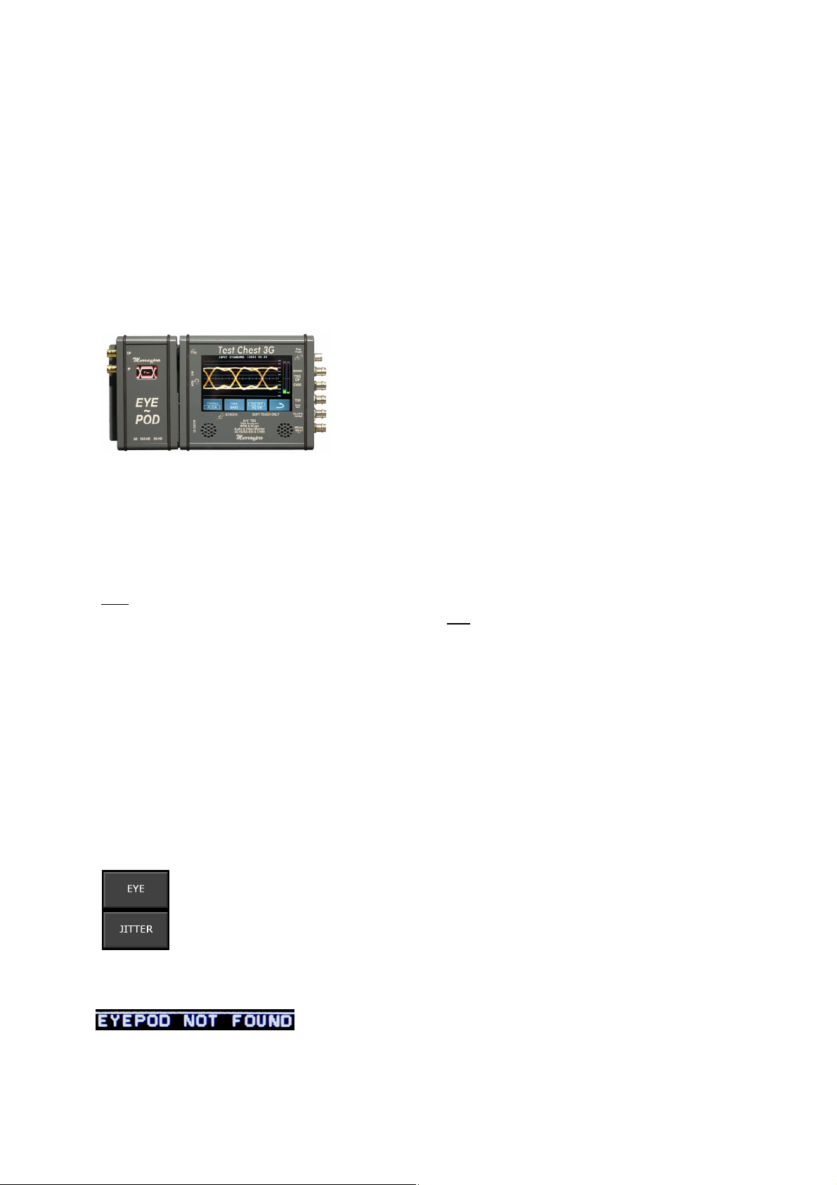
In use, the EYE~POD module simply replaces the AUDIO-POD on its
mounting plate, and when coupled using the keyed slide and toggle locking
mechanism of the mounting plate, is then operated with the TC as if it were the
AUDIO-POD. DC power and logic control is automatically coupled to the EYE~POD
accessory by means of the D-25.
The EYE~POD module has its own dedicated BNC input connector, this is
provided to enable precise input matching for optimum performance with SDI signals
up to, and including 3G.
After the module is activated, a fully equalised
and re-clocked utility output of the EYE~POD's
input signal is available on the adjacent BNC.
When the module is activated, the ‘Eye’ icon on
the Pod's front panel will illuminate, however it
functions only as an indicator and is not an
operational control.
When activated, the EYE~POD draws power
requirement via the D-25 interface connector directly from the TC, and under mains
power the TC will support the EYE~POD module indefinitely. However when running
under internal power, the TC’s normal duration of around 3 hours with a fully charged
battery will be significantly reduced.
The EYE~POD module is offered as an accessory, and may be used with
any Test Chest or Test Chest 3G that has been upgraded and fitted with
appropriate software. EYE~POD modules are not dedicated for use with any
particular unit, so a single Inventory Asset could service several Test Chests.
Operation:
When coupled to Test Chest the EYE~POD module will draw power and
illuminate the front icon ONLY when the Eye feature is actually enabled. Under all
other conditions, even when mated, the Eye module is completely quiescent.
The EYE~POD features are a sub-set of the WFM menu structure of TC,
which is accessed and activated using the main LCD touch screen in the usual way.
The software required to operate the EYE~POD is included with later TC3G units,
but can be retro-fitted to existing earlier TC3G inventory, if absent.
After selection of the WFM icon in the main menu, the "Eye" &
"Jitter" icons will be apparent in the top-right sub-menu. Selection of
either the "Eye" or "Jitter" icon will automatically power up the EYE~POD
module if fitted, or display a message warning that the module is absent
if it has not been detected. If the module is present, and has a valid SDI
input, the selected display will be presented on the TC's LCD panel.
Prolonged selection of the EYE~POD mode, even if
the EYE~POD module is declared as “NOT FOUND”,
will not result in any harm to the TC/TC3G.
Page 32
Test Chest: Manual
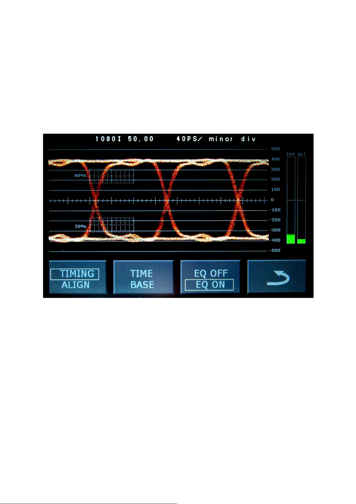
Selection of the accessory’s "Eye" mode will present a triple-function
display showing Eye and a dual histogram feature.
The histogram display shows simultaneous Timing and Alignment jitter
parameters. SMPTE/ITU specify the bandwidths and roll off characteristics required
to display these two jitter parameters correctly, and these parameters will vary with
the input TV standard. These parameters are automatically selected by the Test
Chest, and no manual selection is required.
The histograms’ 50% point represents the specification jitter limit for the
standard in use, and excursions above this limit will be flagged in red.
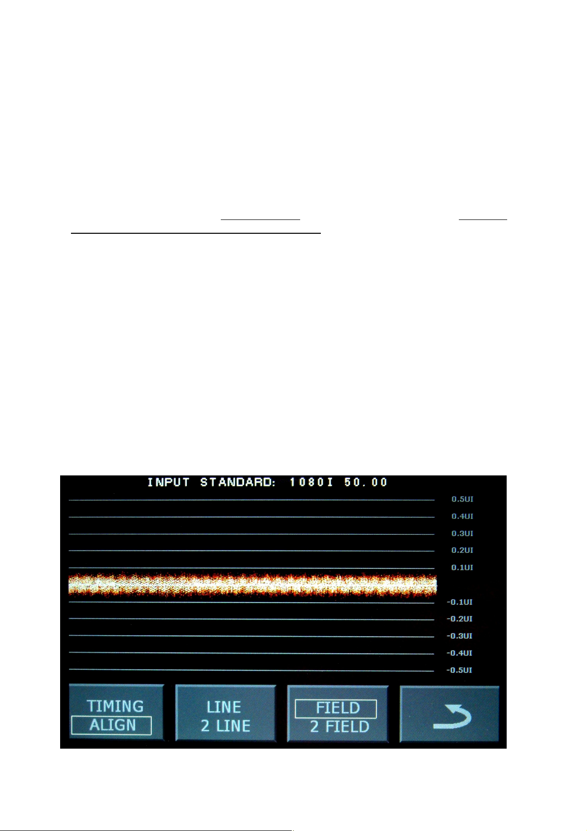
Measurement of Waveform Rise Time
The Main Eye display graticule has two boxes with a number of fine
subdivisions which assist with rise time measurements, this is shown above with a
1080i input signal displayed.
The display timebase is shown on the banner at the top of the LCD panel
(40pS/minor division in the photo above), and the positive or negative going
excursion is positioned by means of the LCD’s 'touch-shift’ so that the leading edge
of the measured transition is at the centre of either the lower (or upper) sub-division
box, as appropriate (in this example, the 20% point of the positive going transition
has been aligned with the start of the timing graticule), and the timing difference to
the 80% point is read off directly in 'subdivision units’, which are then converted
using the time value declared on the banner (Risetime = 3 div @ 40pS/div = 120pS).
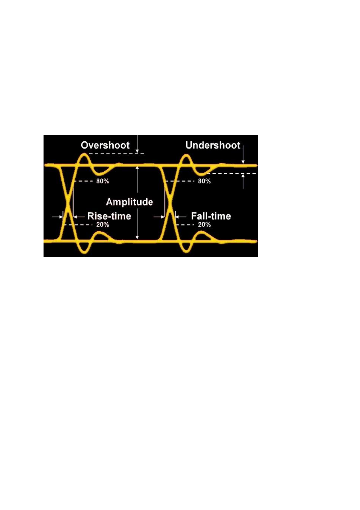
Users should be aware that rise/fall time measurements of SDI signals are
specified to be taken at 20% and 80% points, unlike conventional pulse rise time
measurements which are normally taken at the 10% and 90% points of the overall
amplitude excursion.
Page 33
Test Chest: Manual
These timing measurements are facilitated by the finer subdivisions within
the boxes on the Eye graticule.
Considerations for the display of ‘Timing Jitter’
Be aware that, unlike with some other Eye display units, when the “Timing
Jitter” mode is selected, with EYE~POD the TC's Eye waveform will be presented
with the display timebase using that mode too.
This will result, with respect to the perceived horizontal jitter, in a
significantly noisier display than that obtained using the alternative ‘Alignment’
parameters. However this is quite inevitable if the Eye-POD’s display is to correctly
include these lower frequency jitter components that are implicit with these longer
time constants. The visually less pleasing presentation in “Timing” does not imply
any EYE~POD circuit malfunction, and indeed some competitive Eye products
actually disguise/mask the display of this larger phase jitter through use of
‘inappropriate’ damping, creating (only) the illusion of a subjectively much cleaner
display!
Unless the 'Timing jitter' excursions, as presented on the histogram,
significantly exceed the system's jitter limit, thereby activating the histogram's red
warning flag, jittery SDI signals of this magnitude should be easily tracked by the
local oscillators of normal broadcast equipment.
Users should be aware too that on 3G standards this Specification for
Timing Jitter is very wide indeed, due to the very real technical difficulties associated
with transporting signals of this bandwidth down coaxial cable using BNC
connectors, and subjectively very jittery Eye displays can/will result, although these
are accomodated within the System’s specification and will usually be satisfactory
tracked by the receiving equipment.
The venerable BNC connectors were originally designed in the 1940s,
and were never intended for microwave frequency use at 75W.
Display of the Jitter waveform
Sometimes it is valuable to determine whether there are obvious picture
or perhaps Frame/mains frequency related jitter components, and for this
investigation mode the ‘Jitter’ icon should be selected on the WFM Menu.
A conventional ‘Oscilloscope’ display with control over timebase sweep speeds is
provided to facilitate investigation into system Jitter. The dual histogram is not
presented in this mode and, as with the Eye display, selection of the 'Alignment
mode' will use a more agile and faster tracking mechanism, which results in a less
apparent jitter, than when displayed using ‘Timing mode’.
Page 34
Test Chest: Manual
Jitter measurement filtering
The SMPTE/ITU Standard of the signal source is detected by the
EYE~POD + TC, and this will determine the tracking characteristics of the
PLL/oscillator used for the detection, measurement and display of associated ‘Jitter’
parameters. These ‘Standards dependent’ parameters are automatically preloaded
and will be used for measurements, there is no requirement for manual preselection.
System Specification & Measurement
System specified limits:
Standards: SD SMPTE 259M } Amplitude 800mV +/- 10%
HD SMPTE 292M } Overshoot < 10%
3G SMPTE 424 } Undershoot < 10%
Jitter: Timing HPF 10Hz on SD / HD / 3G
Alignment HPF SD 1KHz
HD 100KHz
3G 100KHz
Alignment Jitter All Std < 0.2UI
Timing Jitter SD < 0.2UI
HD < 1.0UI
3G < 2.0UI
‘LF Drift’ is not a measured parameter, and is excluded by the HPF.
Slew rate: SD 1.5nS max (0.4nS min) Difference 0.5nS maximum
HD 270pS max Difference 100pS maximum
3G 135pS max Difference 50pS maximum
Page 35
Test Chest: Manual
Certification
Test Chest
This is a Class A Product
and is not intended for use
in Domestic Environments
Product is CE compliant.
Declaration: The Equipment meets the requirements of EMC Directive 2004/108/EEC for
Electro Magnetic Compatibility, and Low Voltage Directive 2006/95/EEC for Product
Safety.
EMC Directive:
EN61326-1:2006
EMC requirements for electrical equipment used for measurement.(A)
Electromagnetic emissions:
EN55011/A2: 2002 Radiated & Conducted emissions, Class A.
EN61000-3:2006 Harmonic current emissions. (Not applicable)
EN61000-3-3/2005 Voltage fluctuation and Flicker.
Electromagnetic Immunity:
EN61000-4-2:2001 Electrostatic discharge (B)
EN61000-4-3:2006 RF Radiated Electromagnetic Field (B)
EN61000-4-4:2004 Electrical Fast Transient (B)
EN61000-4-5:2006 Surges
EN61000-4-6:2007 RF Conducted Electro Magnetic Field (B)
EN61000-4-11:2004 Mains dips and interruptions.
Low Voltage Directive
EN61010-1:2001 Mains supply connector (C)
Pollution Degree 2
(A) Correctly shielded leads are required to meet Conformance
(B) Performance may be degraded, but Operator intervention should not be required during recovery.
(c) Mains powered: Class 2 insulation, Indoor use only, in conditions of non-condensing humidity.
Signed:
September 2009
A Drummond-Murray
CEO Murraypro,
Hampton Wick
KT1 4HP UK
(C) Murraypro Nov 2015
 Loading...